Irrigation Using Google Calendar!
by ClemRz in Circuits > Microcontrollers
36647 Views, 367 Favorites, 0 Comments
Irrigation Using Google Calendar!
This Instructable is about making a Google-Calendar-controlled irrigation programmer based on a ESP8266.
How to use it? Add a task to your Google Calendar and the irrigation of your garden/lawn will start when the event begins and stop when it ends!
You love this Ible? Vote here: https://www.instructables.com/contest/Microcontroller2017/
Why I invented that? I don't like the interface of cheap irrigation programmers, the irrigation parameters are not flexible enough and it can't be controlled remotely. I wanted a cheap wifi irrigation programmer but I didn't want to build the entire UI for the ESP8266, I preferred to be able to change the irrigation planning from anywhere with simple means. I decided to have the ESP polling one of my Google Calendars, with events to turn on and off the valve at the correct timing.
How is this made possible? A ESP8266 connects to your Google Calendar via your home Wifi (using a Google Script) and commands a solenoid valve.
What skills are needed? Basic electronics and software programming skills.
What tools are needed? Basic electronics tools, a RS232 USB programmer and a computer.
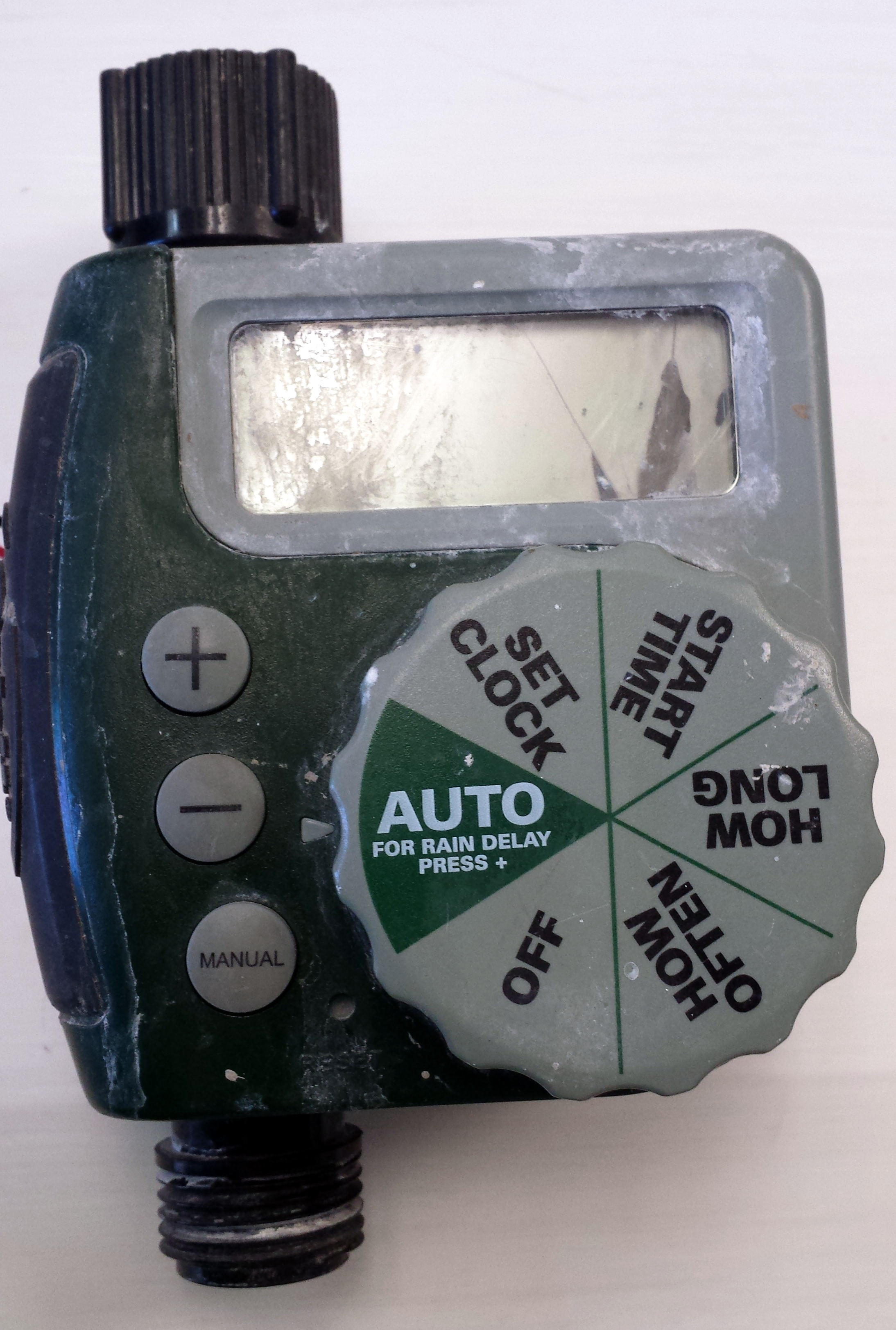
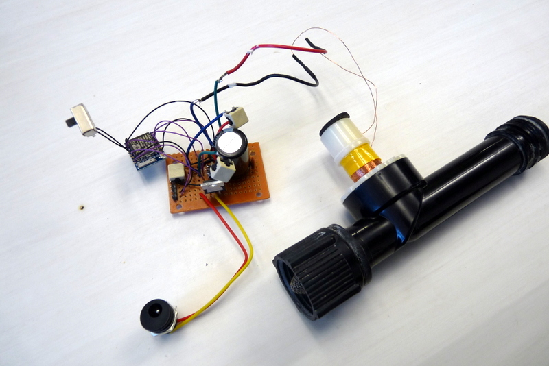
I had a basic irrigation programmer that was useless because its display was broken. I scavenged the solenoid valve and the enclosing for this project.
Parts
We will need several electronic parts:
- 3 x Capacitors (22µF electrolytic, 0.1µF ceramic, 4700µF electrolytic)
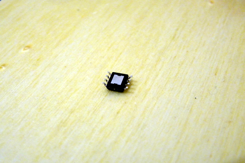
- 1 x DC motor driver (DRV8872 in this case)
- 1 x ESP8266 (version ESP07)
- 1 x 3.3V Voltage regulator (LT1529-3.3 for instance)
- 1 x 12V CC 1.5A charger
- 1 x Female plug (same size as the charger's plug)
- 1 x Prototyping board
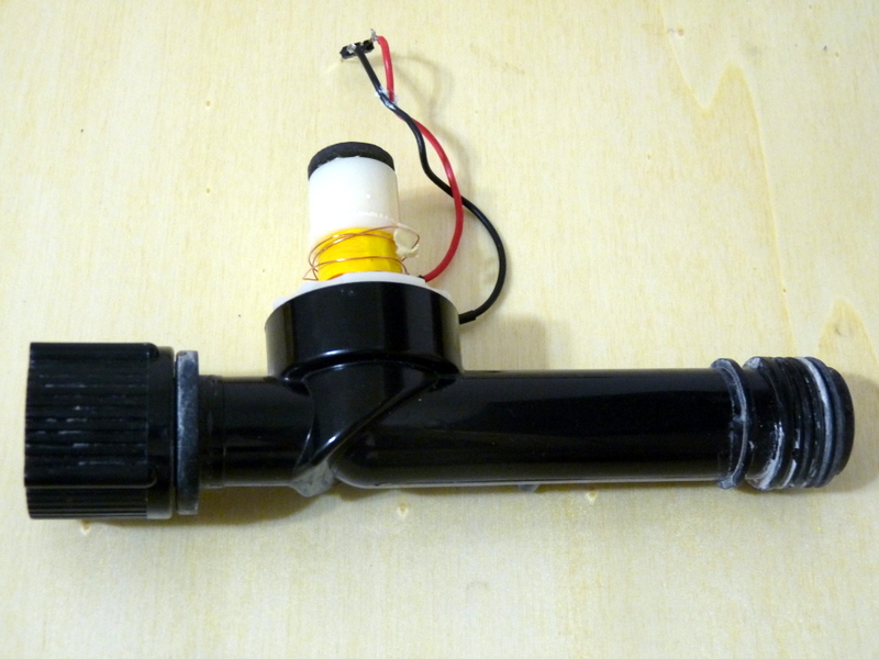
- 1 x Latching solenoid valve (scavenged from an Orbit 58874N)
- 3 x Momentary push buttons
- 1 x Rocker switch
- 3 x Straight male headers
- Some wires
Some basic tools: USB RS232 programmer, pliers, soldering iron, etc.
And a Google Account.
The fact that the valve is a "latching" type (also known as "bi-stable") is important. We can drive it with a DC motor driver/H-bridge. Main advantage: it doesn't require energy to remain open or closed. Main drawback: it is not fail-safe, if for some reason the power goes off then the water will continue to flow if the valve was open (we will add a safety procedure in the ESP's firmware to mitigate that risk).
Build an Adapter for the 8-pin SOP Circuit
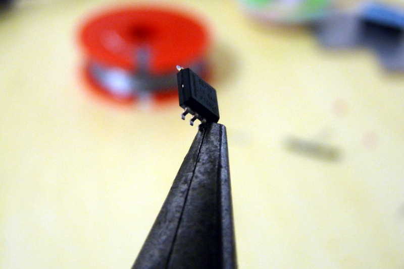


The DC motor driver I have is in a 8-pin SOP package, it is very tiny and I need to build a way to connect it to my prototype board. This is a very delicate process so take your time and be patient.
- Flatten the chip's pins
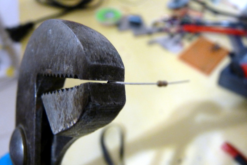
- Flatten the tip of a resistor wire
- Bend the flattened end
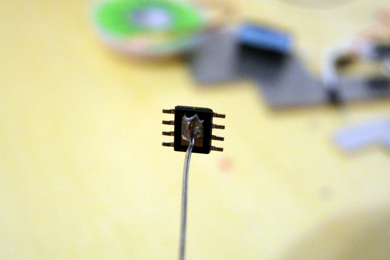
- Solder it to the heat dissipator/sink of the chip
- Cut and solder the wire to the GND of your board
- For each chip's pin, repeat the process
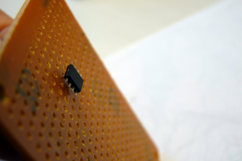
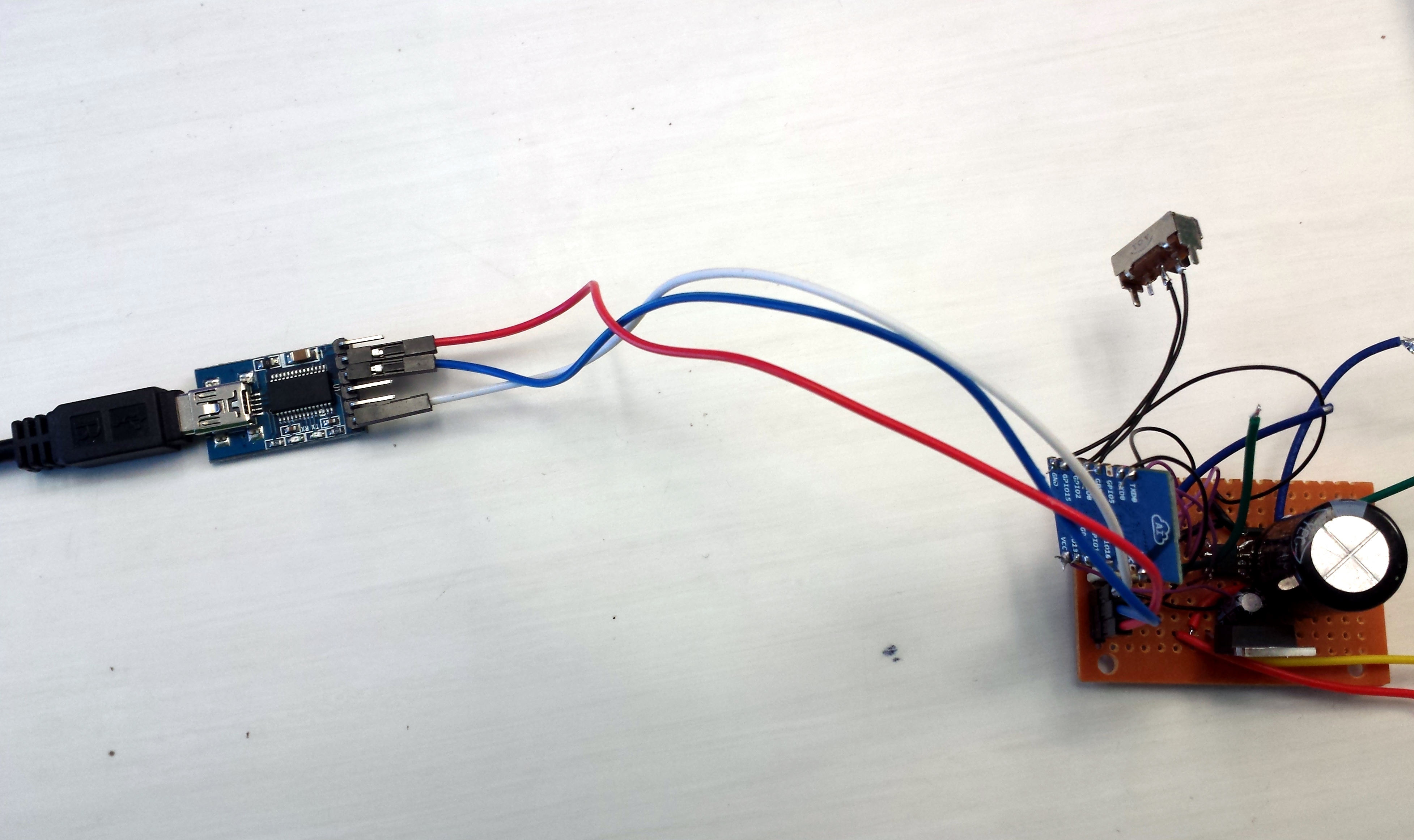
Build the Circuit
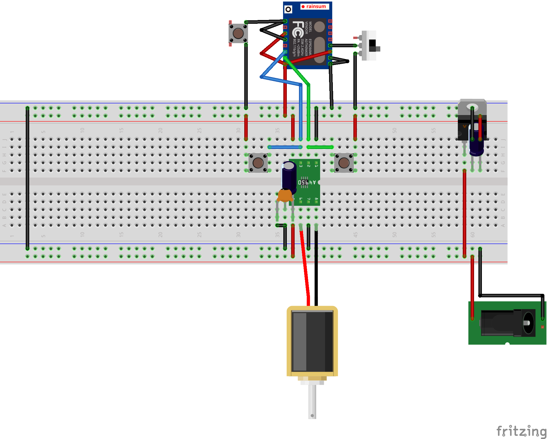
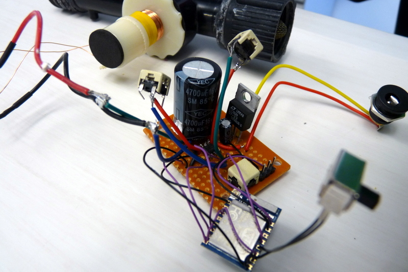
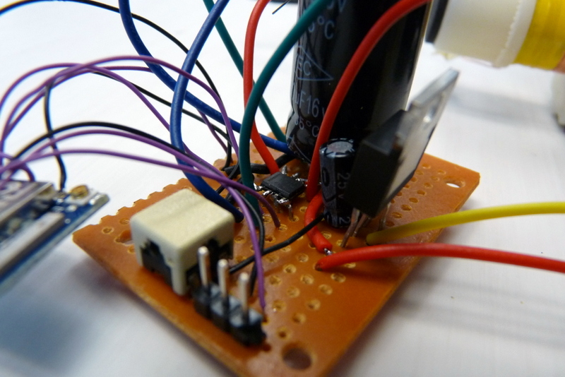
Solder the parts as illustrated (explanations below).

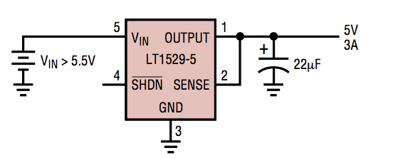
Connect the voltage regulator (datasheet) with basic components as follow:
- VIN pin to 12V CC power source
- OUTPUT pin to SENSE pin
- GND pin to board's GND
Add a 22µF capacitor between OUTPUT and GND as close to the regulator as possible.
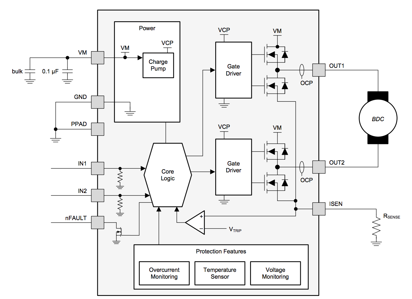
Connect the driver (datasheet) with basic components as follow:
- GND pin to board's GND
- PPAD (heat sink) to board's GND
- VM pin to 12V CC power source
- OUT1 pin to Solenoid red wire
- OUT2 pin to Solenoid black wire
- ISEN to board's GND
Add the bulk capacitor (4700µF) between VM and GND (watch out the polarity) as close to driver's VM pin as possible. Add the 0.1µF capacitor in parallel to the bulk one.
Connect the ESP (documentation) with the switch and buttons as follow:
- One push button between GPIO12 and 3.3V
- One push button between GPIO13 and 3.3V
- One rocker switch between GPIO00 and GND
Use the headers to have an easy access to ESP's Rx, Tx and GND.
Connect the ESP with the voltage regulator as follow:
| ESP8266 | LT1521CST-3.3 |
|---|---|
| VCC | OUTPUT |
| GND | GND |
Connect the ESP with the driver as follow:
| ESP8266 | DRV8872 |
|---|---|
| GND | GND |
| GPIO04 | nFAULT |
| GPIO12 | IN1 |
| GPIO13 | IN2 |
Don't forget to connect ESP's GPIO16 pin to its RST pin (internal wakeup).
Do Some Preliminary Tests
Connect the charger and push one by one the momentary buttons. You should hear a click, that is the solenoid actuating on the valve.
As we probably don't know in which state the valve is closed or open we will need to perform some tests. Try to blow some air through the valve after having pushed and released one of the two buttons. If the air goes through it means that this button is the one that opens the valve. Repeat the process with the other button to clear any assumption.
Take note of the ESP pin to which the open button is connected, and the one that closes the valve too. We will use it to adjust the ESP's firmware.
Create a Dedicated Google Calendar
Many people have a Google Account. This includes the Google Calendar viewer. There you can create as many calendar as you want to.
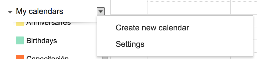
Create a new calendar dedicated to our irrigation system:
- go to https://calendar.google.com and log in
- click on the arrow close to "My calendars" and select "Create new calendar"
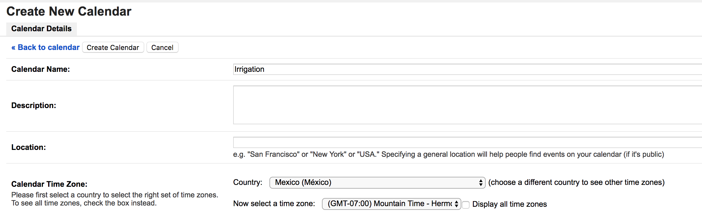
- name this calendar as you wish but keep that name somewhere as we will need it in the next step. "Irrigation" is a good name
- make sure that the time zone is correct according to your irrigation system location
- click on "Create Calendar"
Create a Google Script
A Google Script is a way to create an bridge between a Google product, here your calendar, and outside world.
The Script will be the service we are going to poll to obtain the next events date and duration.
To have access to Google Scripts App you need to:
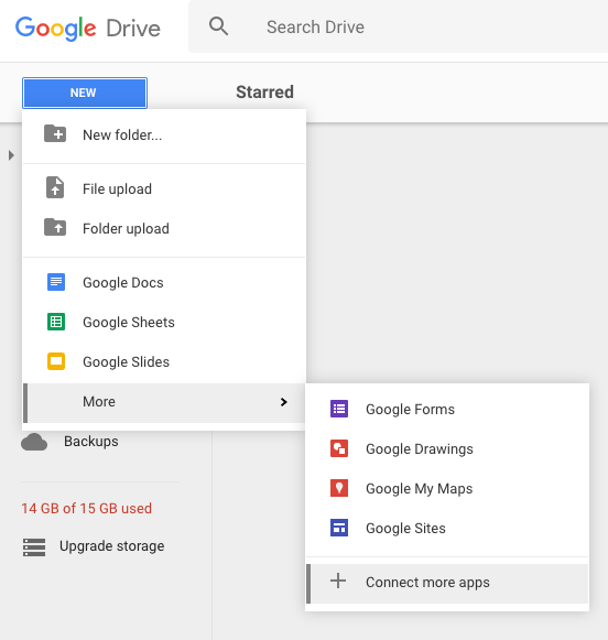
- Go to https://drive.google.com and log in
- Click on New > More > + connect more apps
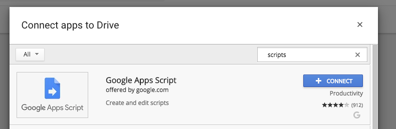
- In the search box type "scripts" and hit return
- Click the "connect" button of the first result
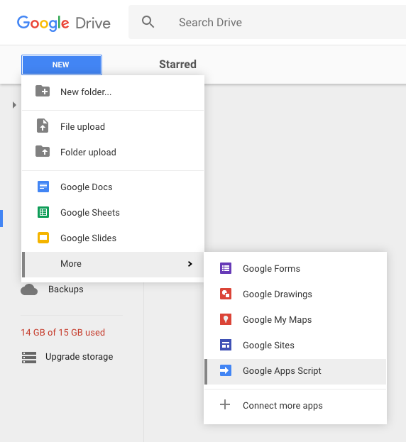
- Back in Drive, click on New > More > Google Apps Script
- Copy and past the script from my Github: https://github.com/ClemRz/GCalendar-Irrigation
- Change the value of _calendarName with your irrigation-dedicated calendar's name
- Click on save and name this script as you wish
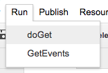
- Click on Run > doGet
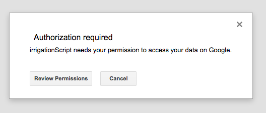
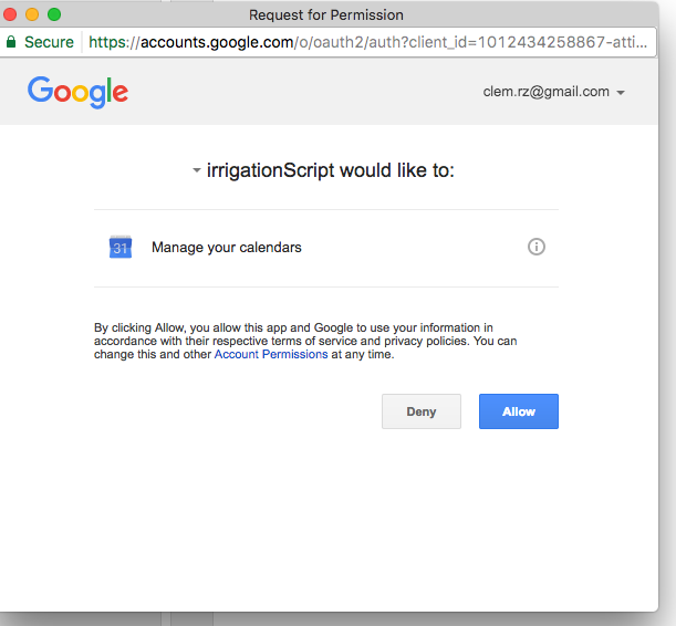
- An authorisation popup should show up, click on "Review Permissions" then "Allow"
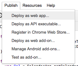
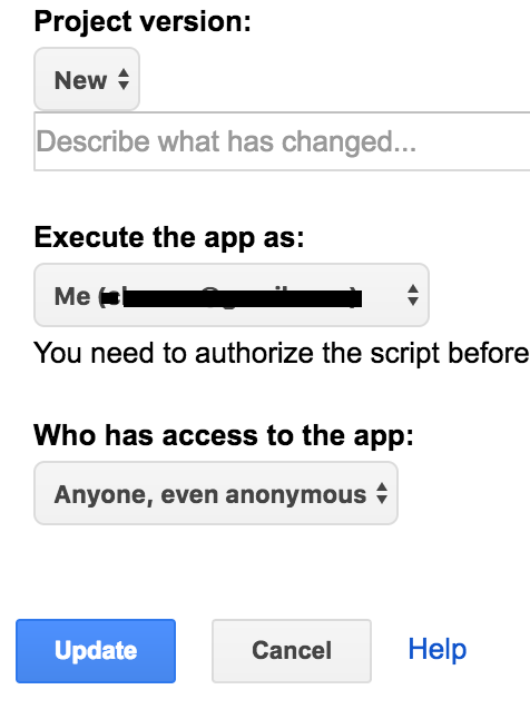
- Click on Publish > Deploy as web app...
- Fill the fields as in the screenshot and hit "Deploy"
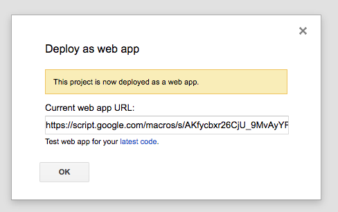
- Copy the url that is provided
You can also change the _checkInRate value which corresponds to the polling rate.
If you want to have a more reactive system, for instance that would detect a newly added event in the minute, change this variable to a lower value. The main drawback of having low values is that your ESP is going to have to poll more frequently i.e. using more bandwidth and more energy.In the other hand, if you don't care about reactiveness but want a more energy efficient system, increase this value.
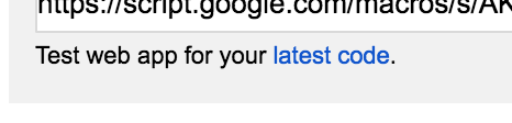
Note: if you change something in your script after publishing you can test using the dev. url in the Deploy window ("Test web app for your latest code."). But the changes won't be reflected to the public url until you update the deploy parameters with a new version (choose "new" instead of the version number).
[Optional] Explanation of the Script
Here are some details about the Google Script.
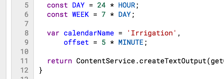
this is where you adjust the name of your calendar and the polling rate:
  var _calendarName = 'Irrigation',
      _checkinRate = 5 * MINUTE;
doGet is the function that's going to be called when you access the URL. It returns a text file (not an HTML one) with the result of the getOuput function:
return ContentService.createTextOutput(getOutput(_calendarName, _checkInRate));
The only goal of this function is to transform a JavaScript plain object (obtained by calling getResponse) into a JSON string:
return JSON.stringify(getResponse(calendarName, offset));
getResponse has the responsibility to create the plain object depending on several situations.
We first try to access to the calendar:
var cal = CalendarApp.getCalendarsByName(calendarName)[0];
If the calendar is not accessible for any reason (typo in the name for instance) then we return an error object:
  if (!cal) {
    return {status: 'error', message: 'Error, calendar "' + calendarName + '" does not exist.'};
  }
If we could open it, then we will get the events (items) that are soon to happen:
  var now = new Date(),
      later = new Date();

  later.setSeconds(now.getSeconds() + offset);

  var items = cal.getEvents(now, later),
      length = items.length,
      response = {};
If there are some events then we format the object accordingly:
  if (length){
    response = getEvent(items[0]);
    if (response.nextCheckIn > offset) response.nextCheckIn = offset;
We also adjust the next checkin rate so it is never greater than the polling rate.
If not, then we let the callee know that it needs to close the valve. Apart from indicating that an event has possibly ended, this also covers the case when the valve could have remained unintentionally open.
  } else {
    response = {closeValve: true, nextCheckIn: offset};
  }
We also let the callee know that everything went well by wrapping the response this way:
return {status: 'success', data: response};
The getEvent function basically do some maths and logic to determine when should happen the next checkin and if the valve needs to be opened or closed.
  var now = new Date(),
      title = item.getTitle(),
      startTime = item.getStartTime(),
      endTime = item.getEndTime(),
      fromNow = startTime - now,
      startsWithin = fromNow < 0 ? 0 : Math.round((fromNow)/1000),
      lasts = Math.round((endTime - (fromNow < 0 ? now : startTime))/1000),
      response = {title: title};
If the event already started then fromNow will be negative, we let the callee know that it needs to open the valve and the next checkin will correspond to the end of the event:
  if (fromNow <= 0) {
    response.openValve = true;
    response.nextCheckIn = lasts;
If the event is not started yet then we let the callee know that the valve needs to remain closed and the next checkin will be the starting date of the next event:
  } else {
    response.closeValve = true;
    response.nextCheckIn = startsWithin;
  }
We increment the nextCheckIn to prevent returning zero. If the ESP try to deep-sleep for 0 microseconds it would never wakeup by itself and it would be catastrophic:
  response.nextCheckIn++;

  return response;
[Optional] Log the Interactions in a Spreadsheet in Order to Have Visual Control
If you want to make sure that your irrigation system is actually calling your Google Apps Script I recommend to do the following:
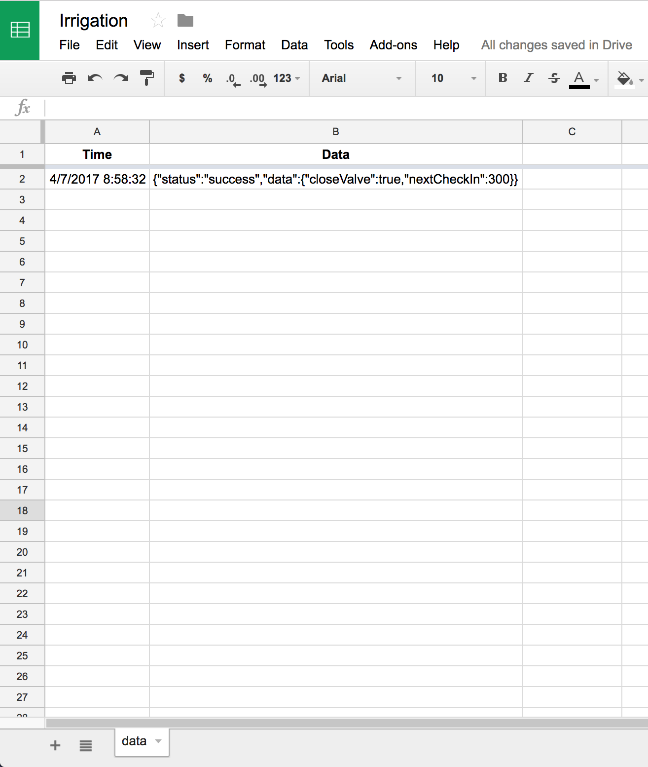
- Create a new spreadsheet in your Drive, name it "Irrigation"
- Rename the first sheet to "data"
- Add some headers to the first row: "Time" and "Data"
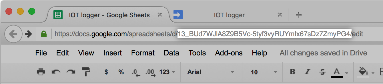
- Copy the ID of your spreadsheet, you will find it in the URL
- Add this function to your Script:
function logToSpreadsheet(data) { var ss = SpreadsheetApp.openById('paste_here_your_spreadsheets_id'), sheet = ss.getSheetByName('data'); sheet.appendRow([new Date(), data]); } - Modify the getOutput function:
function getOutput(calendarName, offset) { var response = JSON.stringify(getResponse(calendarName, offset)); logToSpreadsheet(response); return response; } - Publish a new version of your Script (Publish > Deploy as webapp > Project version: new > Update)
Wait for the ESP to call the Script, you should see a new row of data appended to the "data" sheet. This is the proof that your system is actually reaching the Script.
Upload the Firmware to the ESP
There are tons of tutorials in the Internet on how to upload firmwares to the ESP. I also wrote a DIY which contains this part here: https://www.instructables.com/id/IoT-Door-Alarm-UPGRADED/
- Download and install those libraries in Arduino/libraries folder:
- ArduinoJson: https://github.com/bblanchon/ArduinoJson
- HTTPS redirect: https://github.com/electronicsguy/ESP8266/tree/master/HTTPSRedirect
- Download the firmware from my github: https://github.com/ClemRz/GCalendar-Irrigation/tree/master/software%20design/ESP8266_gcalendar_irrigation
- Open it with the Arduino IDE
- Change the following parameters:
- SSID: your home wifi's network name
- PASSWORD: your home wifi's password
- SCRIPT_ID: your Google Script ID (from the URL you copied previously)
- CLOSE (pins allocation section): the ESP's input connected to the close button (you took note of it previously)
- OPEN (pins allocation section): the ESP's input connected to the open button (you took note of it previously)
- Set the ESP in programming mode (GPIO0 connected to GND)
- Hit the upload arrow
- Set the ESP in running mode (GPIO0 disconnected from GND)
I wrote this code getting inspiration from https://github.com/wilda17/ESP8266-Google-Calendar... and https://coertvonk.com/technology/embedded/esp8266...
[Optional] Explanation of the ESP Firmware - Main Functions
The main sketch of the ESP's firmware is explained here.
In the setup function we initialise the Serial port, the pins (IO stands for Input Output) and the connection to the Wifi network (see next steps for more details):
void setup() {
#if DEBUG
  initSerial();
#endif
  initIO();
  initWiFi();
}
In the loop function we try to contact the Google Script.
We first check if we are connected to the network:
void loop() {
  if (_attempts <= MAX_WIFI_ATTEMPTS) {
In the case we are connected, we first reset the attempts counter and then try to get the Google Script's response (more details about httpsGet in next steps):
    _attempts = 0;
    String response = httpsGet();
Then we test if the response is not empty (successful answer):
if (response != "") {
And we process the message returned by the Google Script (more details about process below):
process(response);
If the answer was empty then we close the valve as a safety measure (more details about closeValve in next steps):
} else closeValve();
If we are not connected to the network then we close the valve as a safety measure:
} else closeValve();
We finish by setting the ESP asleep (more details about sleep below):
  sleep();
}
The process function will decide what should be done depending on the Google Scrip's answer.
We first deserialise/parse the response as a JSON object and check the consistency of that object:
void process(String response) {
  StaticJsonBuffer<200> jsonBuffer;
  JsonObject& root = jsonBuffer.parseObject(response);
  if (root.success()) {
If the object is consistent then we check the status returned by the Google Script:
    String status = root["status"];
    if (status == "success") {
If the answer is a success then we extract the polling rate:
_pollingRate = root["data"]["nextCheckIn"];
We do a sanity check on the polling rate, the ESP cannot sleep for more than 71 minutes:
if (_pollingRate > MAX_SLEEP_TIME) _pollingRate = MAX_SLEEP_TIME;
If the answer indicates that the valve needs to be opened then we do so (more details about openValve in next steps):
if (root["data"]["openValve"]) openValve();
If the answer indicates that the valve needs to be closed then we do so:
if (root["data"]["closeValve"]) closeValve();
If the status is not a success then, as a safety measure then we close the valve:
    } else {
#if DEBUG
      Serial.print(F("Unsuccessful response: ")); Serial.println(status);
#endif
      closeValve();
    }
If the object is not consistent then, as a safety measure then we close the valve:
  } else {
#if DEBUG
    Serial.println(F("Failed to parse JSON"));
#endif
    closeValve();
  }
}
The sleep function puts the ESP into deep sleep mode for a specific amount of time, in this case the polling rate. If the value of _pollingRate is equals to zero then the ESP will never wakeup by itself, this is the reason why we do a sanity check on it.
void sleep() {
#if DEBUG
  Serial.print(F("Go to sleep for "));
  Serial.print(_pollingRate);
  Serial.println(F("s."));
#endif  //DEBUG
  if (_pollingRate == 0) _pollingRate = 1;
  ESP.deepSleep(_pollingRate * MICROSEC);
}
[Optional] Explanation of the ESP Firmware - Initialisation Functions
The initialisation sketch of the ESP's firmware is explained here.
In initSerial we initialise the Serial communication for debug messages:
void initSerial(void) {
  Serial.begin(9600);
  Serial.println();
  //Serial.setDebugOutput(true);
}
In initIO we set the OPEN and CLOSE pins as outputs and the N_FAULT pin as an input, using the internal pullup resistor (see driver's datasheet):
void initIO(void) {
  pinMode(N_FAULT, INPUT_PULLUP);
  pinMode(OPEN, OUTPUT);
  pinMode(CLOSE, OUTPUT);
}
[Optional] Explanation of the ESP Firmware - Valve Functions
The initialisation sketch of the ESP's firmware is explained here.
The openValve and closeValve functions call the actuateValve passing a boolean as an argument:
void openValve(void) {
  actuateValve(true);
}

void closeValve(void) {
  actuateValve(false);
}
The actuateValve simply decides which pin needs is concerned depending on the argument. As this is a latching (bi-stable) valve we set the pin high for a small amount of time (10ms here). In between we check if the driver indicates a fault:
void actuateValve(bool openValve) {
#if DEBUG
  Serial.print(openValve ? F("Open") : F("Close")); Serial.println(F(" the valve."));
#endif
  int pin = openValve ? OPEN : CLOSE;
  digitalWrite(pin, HIGH);
  delay(5);
  lookForFault();
  delay(5);
  digitalWrite(pin, LOW);
}
To detect if there is a fault we read the N_FAULT pin. Looking a the driver's datasheet we know that there is a fault when this pin is low. We log a message when we detect a fault. You can add some logic here to send an email for instance:
void lookForFault(void) {
  bool isInFault = digitalRead(N_FAULT) == LOW;
#if DEBUG
  if (isInFault) {
    Serial.println(F("Driver is showing a fault"));
  }
#endif
}
[Optional] Explanation of the ESP Firmware - Wifi Functions
The wifi sketch of the ESP's firmware is explained here.
We first enable the persistent mode. This allows the ESP to "memorise" the network it was connected to previously and speeds up the connection process. Then we check if we are allready connected to a network:
void initWiFi(void) {
#if DEBUG
  Serial.println(F("Start WiFi"));
#endif
  WiFi.persistent(true);
  if (WiFi.status() != WL_CONNECTED) {
If we are not yet connected to any network then we request the connection. We periodically check the status of the connection. This loop is limited by a max attempts amount to prevent lockups. The yield function allows task to be ran on background and prevents other types of lockups.
    WiFi.begin(SSID, PASSWORD);
    while (WiFi.status() != WL_CONNECTED && _attempts <= MAX_WIFI_ATTEMPTS) {
      yield();
      delay(500);
#if DEBUG
      Serial.print(F("."));
#endif
      _attempts++;
    }
  }
Once we either are connected to the network, or reached the max attempts amount, we log some information:
#if DEBUG
  Serial.println();
  if (_attempts > MAX_WIFI_ATTEMPTS) {
    Serial.print(F("Failed to connect to "));
    Serial.println(SSID);
  } else {
    Serial.print(F("Connected to "));
    Serial.println(SSID);
    Serial.print(F("IP address: "));
    Serial.println(WiFi.localIP());
    Serial.print(F("Mac addresss: "));
    Serial.println(WiFi.macAddress());
  }
#endif
}
[Optional] Explanation of the ESP Firmware - Client Functions
The client sketch of the ESP's firmware is explained here.
The httpsGet function has the responsibility to get the response from the Google Script.
We try to connect to the Google Script's host several times before giving up:
String httpsGet(void) {
  HTTPSRedirect* client = new HTTPSRedirect(HTTPS_PORT);
  bool connected = false;
  for (int i=0; i<MAX_HTTPS_ATTEMPTS; i++){
    yield();
We check the https connection status:
    int retval = client->connect(HOST, HTTPS_PORT);
    if (retval == 1) {
If we are connected we set up a flag and exit the loop:
       connected = true;
       break;
If we are not connected we output some debug information and loop again after a small delay:
#if DEBUG
    } else {
      Serial.println(F("Connection failed. Retrying..."));
#endif
    }
    delay(HTTPS_REINTENT_DELAY*MILLISEC);
  }
If we couldn't connect, after several attempts, then we return an empty string:
  if (!connected) {
#if DEBUG
    Serial.print(F("Could not connect to server"));
#endif
    return "";
  }
If we could connect to the host then we request the url:
if (client->GET(URL, HOST)) {
If the server answered successfully we get the response it sent:
    String payload = client->getResponseBody();
#if DEBUG
    Serial.println(F("HTTP Response: "));
    Serial.println(payload);
#endif
If the response contains the success phrasing then we return the message:
if (payload.indexOf(SUCCESS) >= 0) return payload;
If not, we return an empty string:
#if DEBUG
    Serial.print(F("Script returned failure message: ")); Serial.print(payload);
#endif
    return "";
In the case we couldn't connect to the URL then we return an empty string:
  } else {
#if DEBUG
    Serial.print(F("Couldn't get the body, code: ")); Serial.print(client->getStatusCode()); Serial.print(F(", message: ")); Serial.println(client->getReasonPhrase());
#endif
    return "";
  }
Finally, we free the memory from the connection information:
  delete client;
  client = NULL;
}
Test the Calendar Connectivity
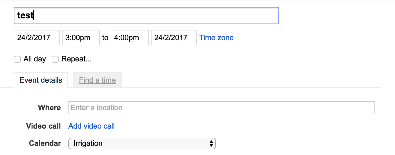
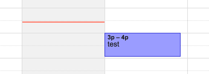
Set up an event which starts within a few minutes and last 2 minutes and check that the valve reacts properly according to that timing.
Protect the Circuit in an Enclosure
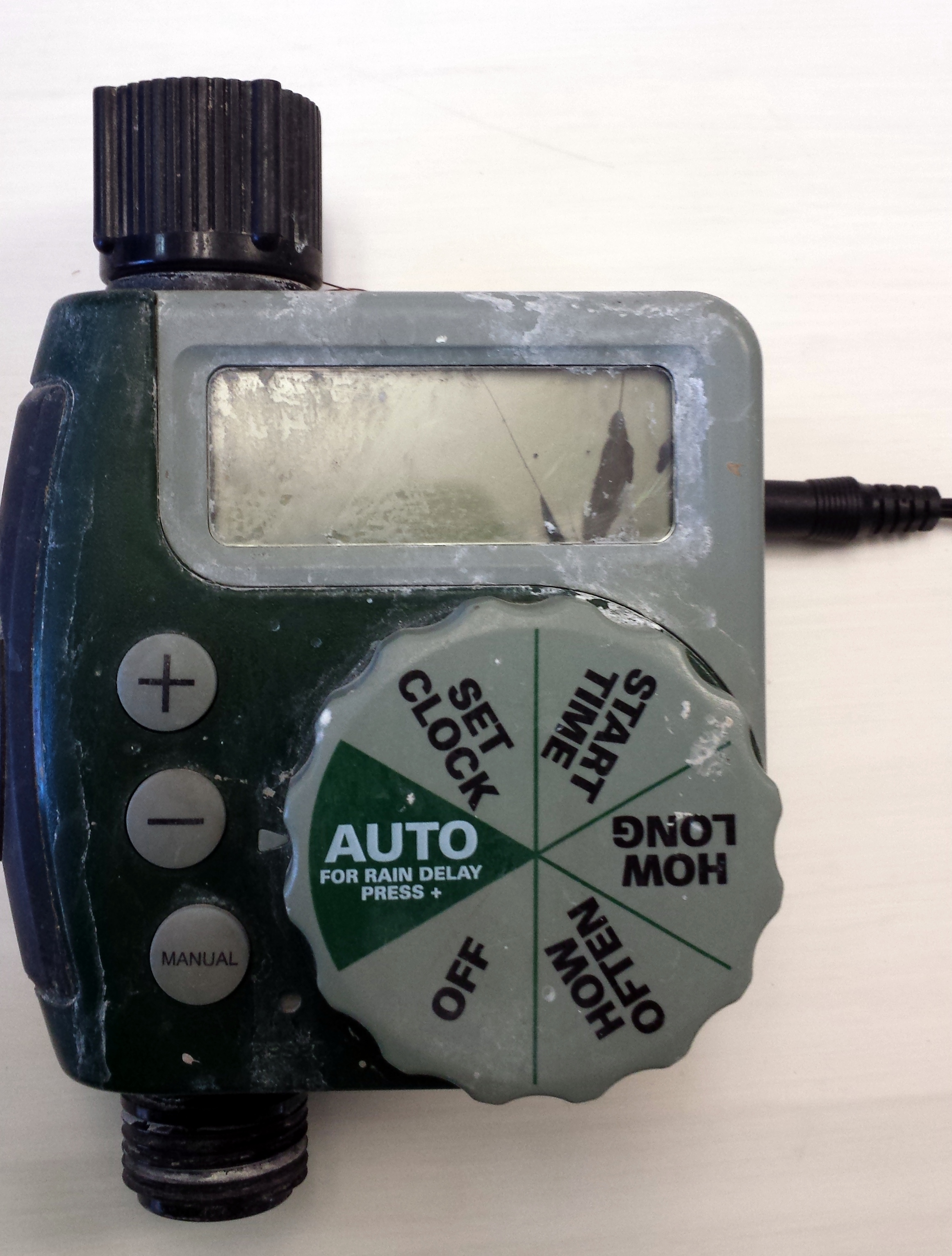
I reused the original programmer's enclosure.
Final Thoughts
This project was a real challenge to figure out. But it was fun to build and is quite cheap and reliable!
Here are some nice features:
- You can add recurring events in your calendar for quick setup
- We can think of controlling multiple irrigation systems in one single place
- The calendar can be shared to be collaborative if you need more people to control the irrigation system
- Using an automation third party system like IFTTT we can add events automatically depending on the weather for instance
- ...
The main drawbacks of this device are:
- Useless when the power or the Internet/network goes off
- Needs a Wifi signal close/strong enough
- Needs a power source
Some enhancements can be added (power on batteries, hall-effect sensor to have a feedback on the position of the valve, etc.) so feel free to comment and post your own project below! :)
Enjoy.