Intrusion Detection and Deterrent Demonstrator
by dwaynebates89 in Circuits > Raspberry Pi
169 Views, 1 Favorites, 0 Comments
Intrusion Detection and Deterrent Demonstrator


This is basically a simulation of a system that could be implemented in a home to detect and deter intruders.
Supplies
Materials
- Assorted machine screws m2-m5 varying lengths
- 4" c-clamp x2
- Heat Sets metric m2-m5
- raspberry pi 4b
- 110v to 36v step down module
- 5v buck converter x3
- proto board assortment
- 400kv step up module
- solder
- 22 awg wire roughly 125 feet
- 22 awg heat shrink
- 22 awg wire connectors
- Logic controlled relay x6
- assorted jumper wires.
- 30mm fans x2
- PIR sensor
- USB camera
- pla fillament 1 roll
- Led Green x70
- Led Red x50
- Led Blue x50
- Led White x50
- assorted wood screws
- 2x4's 8 foot x 3
- a sheet of ply wood i used 5/8 sheathing
- PCB barrel connector female
- Barrel connector with 2 conductor pig tail male
- A length of wire with two 18 gauge conductors.
- A two prong AC outlet plug.
- clear plastic sheets
- high strength double-sided sticky tape.
- assorted value resistors.
- 1 1"x2"x8' piece of wood
- OPTIONAL spray paint.
- bluetooth speaker
- zip ties
- Solderable USB C connectors
Tools
- 3D Printer
- wire cutter and stripper
- jig saw
- some combination of skill saw chop saw or table saw.
- screw driver with assorted bits Phillips and hex
- soldering iron kit
- optional magnifying glass
- power drill
- scissors or utility knife
Assemble Control Box


- 3D print the attached file c_box.stl and print and assemble the gland nut as per the included directions found here
- install the appropriate sized heat sets into the mounting holes on the c_box.stl print. Click here for instruction on installing heat sets.
- Install the 2 fans with through hole bolts according to attached picture.
- solder a female PCB barrel jack connector to one of the protoboards lining up with the hole as seen in the bottom right corner of the layout picture.
- Install the Raspberry pi, proto boards, 3- 5v buck convertors, the 36v step down module and 2 of the logic controlled relays with the appropriately sized screws according to the layout in the attached picture.
- install heat sets on gland nut holes and attach them with appropriate sized screws as per picture.
Downloads
Assemble the Control Box Cover

- 3D print the attached files cover.stl, cover_insert.stl and TWO led_strip_cover.stl
- insert 10 green leds and appropriate value of resistor to limit voltage into the led strip cover.stl
- solder them in series for information on led in series click here for information on calculating correct resistor values click here
- repeat
- cut a sheet of plastic to fit in the recessed channel on the bottom of the cover.stl
- use double-sided tape on the recessed channel and then place the cut sheet in the channel.
- Put double-sided tape on the outside edges of the cover insert
- insert the cover, sandwiching the plastic in-between the insert and cover.
- place double sided sticky tape on the bottom of the LED strips and place them on two sides of the cover BOTTOM. Aiming downward towards the base of the box.
Assemble Taser Module


- 3D print taser_module.stl and taser_cover.stl and taser_bracket.stl
- install heat appropriate sized heat sets in premade holes
- install the taser module with the red and black wires going out the holes in the back of the taser module and screw down the bracket with appropriate sized screws
- Roll some double-sided sticky tape around the two remaining wires and slide them down into the two wire stands on the front of the module as seen in the attached picture.
- cut an appropriately sized sheet of plastic to fit in the recessed channel in the back of the taser_cover.stl.
- place this sheet of plastic in the recessed channel with some sticky tape.
Assemble TOP Panel

- 3D print 20- led_strip.stl, 4- relay_stand.stl, 5 proto_stand.stl and 1 speaker_grill.stl as well as a cable nut from the control box step and a camera case and mount found here
- cut an 18"X32" peace of plywood
- cut 1x2 into appropriate strips to create edging as seen in the picture.
- drill and screw the strips down to the plywood creating a small boarder. 1" face down on the plywood.
- Cut a hole using your jig saw in the center of the board using the speaker grate as a guide NOTE MAKE SURE TO KEEP ENOUGH BOARDER TO SCREW THE GRILL TO THE PLYWOOD.(see attached picture for placement)
- OPTIONAL paint the wood panel.
- Install heat sets in the relay_stands and proto_stands.
- Install proto boards and relays on to their stands
- adhere the relays and proto boards to the panel in the layout pictured.
- Solder 10 LEDS in series with a current limiting resistor. Please see step 1 for information on LED series wiring. for convince in later wiring, I would put a lead wire on either end of the led strips. Complete this process with 5-10 LED per color strips each of all 4 colors(red,green,white,blue) totaling 20 strips. I printed them in multiple colors to differentiate, as LEDs are clear when off.
- adhere these strips in the layout seen in the attached photo.
- Drill a hole about the size of the glad nut through way. Then screw down the gland nut with woods screws as seen in the center of the panel opposite the speaker grill (blue cable nut)
- Screw camera base in center of panel behind the speaker grate facing the relays. Mount this on the 1" face for best viewing. then assemble according the readme included using machine screws and nuts.
- throw your bluetooth speaker in the hole behind the speaker grate.
FINAL ASSEMBLY


- 3D Print control_mount.stl. and the PIR sensor case and mount found here
- 3D print cable_tray.stl ***** the amount depends on how much you value cable management.
- cut 2-2x4s down to 7'
- cut two pieces of 24"x18" plywood
- cut two 22.5" lengths of 2"x4"
- cut two doubled ended 45-degree angle braces as pictures in attached picture. Also for more information about cutting 45 degree angles click here
- Assemble the wood frame as pictures using the 7" 2x4's for the long posts, 22.5 base piece attached to the plywood and of course your 45 degree brace.
- attach the top panel as pictured using the c-clamps as pictured.
- Cut a hole in the center of 5x7" pieces of plywood using the taser module box back as a template.
- attach the 5"x7" pieces on both posts about 26" down from the top of the post making sure the taser module box and fit into the hole appropriately.
- drill some holes in the plastic on the taser module covers in the SAME pattern as pictured. Creates a safety barrier but still allows for intimating sound.
- insert the taser modules into the mounts and place the covers over them, securing the cover and box itself with wood screws.
- assemble the PIR sensor case and mount according the included readme
- mount the sensor about 4" down from the top of one of the posts on the inside of the "doorway" as pictures
- install appropriately sized heatsets into the control_mount.stl two center holes. Then screw it to one of the posts on the outside of the "door way".
- attach the control box using the appropriate sized screws.
- install cable trays at your discretion for wire management purposes.
The Wiring


i designed this to be modular and be dissembled. So it's wired with connectors, this can be done with just running straight wires.
LED Panel
- there are 4 proto boards in the middle of the panel. one designated for each LED color. Use this proto board as a "bus bar" using one half as a positive+ and one half as a negative - making sure there is clear separating of the two halves. I made my connections in a slightly archaic manner of soldering my wires into larger solder globs. it's crude but quick. Wire all 5 strips of each color to one board in parallel for information about wiring leds in paralell click here. Repeat this for all 4 colors.
- the fifth protoboard acts as a feeder board to the the leds. This board also should be separated in half with positive+ and negative- sections same as the LED boards. run wires from the positive+ and negative- side of each color protoboard to the to the corresponding side of the feeder board creating a paralel wiring scheme. designate a small part of the feeder board big enough to accommodate 5 isolated connectors.
- each of the four relays has an input and output on screw down blocks they are labeled on the board. all four of the outputs will be wires to the corresponding positive and negative side of the feeder board.
- the output of the relays will go to to the negative and positive of the 4 different color LED proto boards. 1 relay for each color board.
- there should be two lead wires attached to the positive and negative side of the feeder board to be ran out of the cable nut giving enough space to solder on a pigtail later.
- each relay has a logic ground and logic 5v connection through hole mount these can be soldered on connection. all logic grounds will be wired to the small designated section on the feeder board. Then solder an additional lead wire that runs out of the cable nut, thus creating a common logic ground for all 4 relays with one wire heading to the control board.
- each of the logic 5v connections will be a lead wire going out of the cable nut.
- I soldered, applied heat shrink and assembled the wire connectors as per the directions that comes with the kit (see attached picture)and put female connectors on the end of the wires after securing them tight with the cable nut.
Control Box
- solder two small lead wires connecting to the positive+ and negative- legs of the barrel jack connector on the protoboard.(for information on doing this click here
- run these two wires to the input of the 110v-36v step down transformer this is labeled on the board.
- the protoboard in the middle of the box is setup similar to the feeder board on the LED panel. I has a 36v section separated with a positive+ and negative- sides as well as an ISOLATED 5v with a positive+ and negative- side. Solder one wire to the 36v negative- and 36v positive+
- insert the 36v positive and 36v negative wire into the corresponding positive and negative terminals of the 36v step down transformer WARNING POLARITY MATTERS NOW
- all three positive input wires and all three negative input wires of the 5v buck converters will be soldered to the 36v positive and negative sides of the proto board.
- solder one of the negative and positive 5v buck converter wires to the negative and positive sides of the solderable usb c connector and then plug it into the usb-c port of the raspberry pi.
- solder a wire long enough to give some slack to get the cover on and off to both the negative and positive sides of the 5v section of the proto board. Then put a female connector on them. This will be the connector for the LED lights in the cover.
- the two relays towards the front of the board are for the two taser modules. These are the same relays as on the LED panel. The inputs of the relays will go to the positive and negative sides of the 5v section on the protoboard. again solderblobs are crude, but effective.
- for the positive and negative outputs of both relays insert a wire long enough to reach out of the cable nut and solder and heatshrink a connector onto. There will be a total of 4 wires.
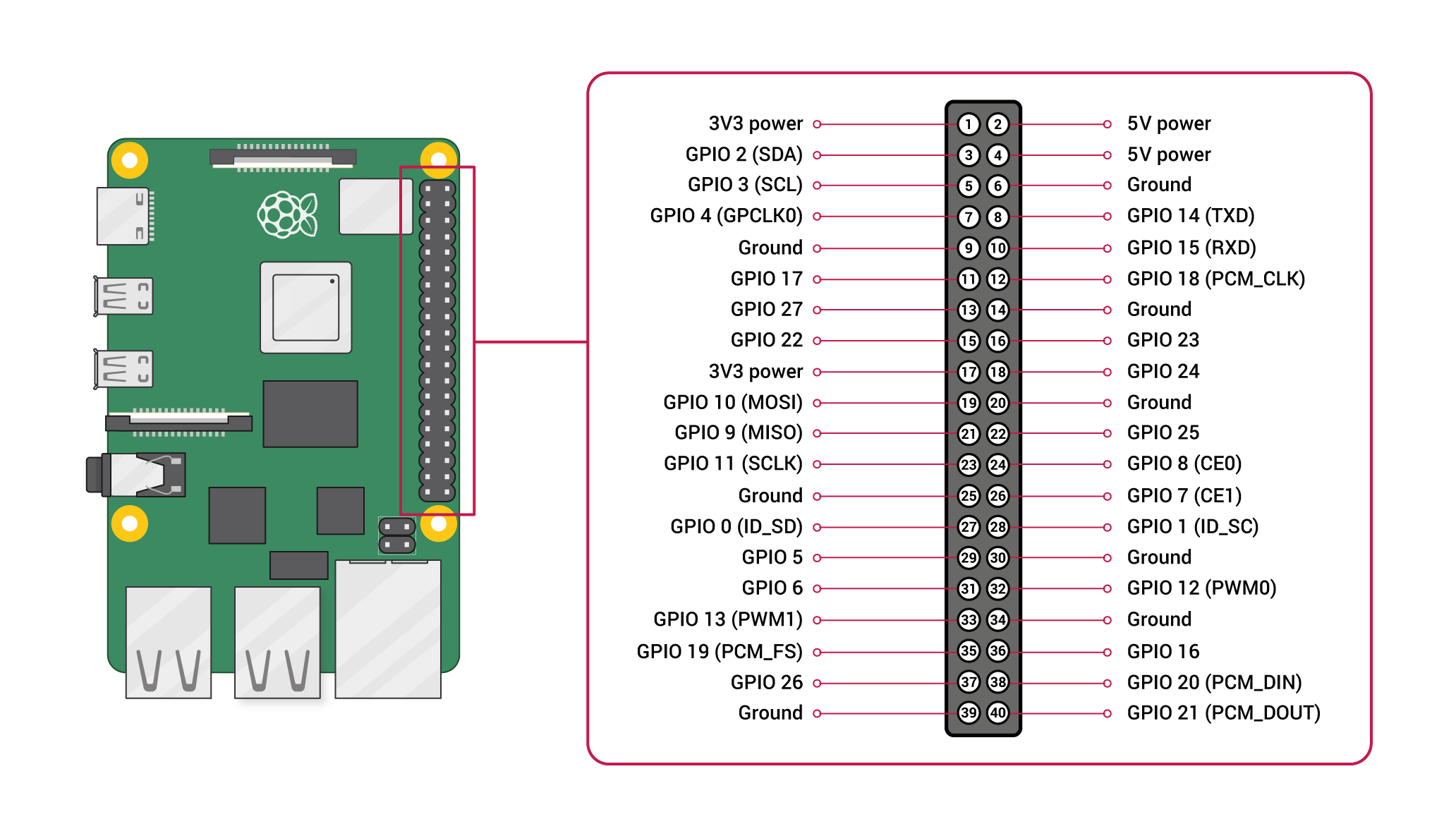
- for the Logic negative- of both relays we will cut a female to female jumper cable in half, strip the ends and solder to the through hole logic negative- then plug the female ends into one of the many ground pins on the raspberry pi (see Raspberry Pi pinout here
- we will do the same for the logic 5v except they will go to pins 20 and 21
- solder an additional wire to positive and negative sides of the 5v section of the protoboard. these wires need to long enough to extend out of the cable nut and put a connector one. these are the power wires for the PIR sensor.
- cut another female to female jumper in half strip the ends. Solder and heatshrink a wire long enough to extend out of the cable nut to one end. the female end will connect to pin 25 on our raspberry pi. This is the data wire for the PIR sensor.
- Cut two female to female jumper cabled in half. then solder a wire on each of these long enough to exit the cable nut and solder heat shrink and connect onto it. This is a total of four wires for the four LED wires coming from the LED panel.
- white goes to pin 16
- blue goes to pin 24
- red goes to pin 12
- green goes to 16
- tighten the cable nut securing the cables.
- put some double sided tape along the edges of the cover, connect the led connector and install the cover.
Control box cover
- connect the positive and negative ends of the two led strips together
- solder a lead wire on the combined negative and on the combined positive ends. Thus creating a parallel connection. Solder and heatshrink connectors on this to correspond to the connector we soldered the control box power board earlier.
Cabling
- i made cables to connect every thing. I did this by soldering on the connectors to lengths of wire that reached my destination conforming to my cable management tastes. I then put baby zip ties every so many inches to keep the cable together. You can see the attached picture for reference.
- you need two 2 pin cables for the taser modules to the control box
- one 3 pin cable for the PIR sensor
- one 4 pin cable for the 4 color boards from LED panel to control box
- one 3 pin cable for the 36v positive+, 36v negative- and the logic negative- going to the LED panel to the control box.
- additionally there is a usb cabled for the camera that goes to the usb 2.0 port of the raspberry pi.
- I made my own power cable by soldering on a pigtailed barrel jack connector to the 18g 2 conductor wire, heat shrinking, and install a two prong AC plug(for information on how to do this click here)
- now connect all the cables from the control box to there respected destinations.
DISCLAIMER
I RECOMMEND FINDING AN ALTERNATIVE CONNECTOR. ALTHOUGH IT WORKS WITH AN AC CONNECTION, IT IS VERY EASY TO SHOCK YOUR SELF WITH THE BARREL CONNECTOR.
Coding

How it works
The code is setup so that when mon.py is ran it will turn on the white lights and start monitoring for motion on the PIR sensor, simulating a home ready to be intruded upon. When motion is detected it will execute two additional python scripts simultaneously. one main.py will start the sound playing and led display as seen in the demonstration video. The second script send.py will start taking a series of pictures at a programmed interval and then send them to the specified email address using gmail smtp servers. after the demonstration is done. It will also clear the images from the computer after sending them. There are a couple of things needing to be done to make this work for your specific case.
copy all of the attached files (main.py ,mon,py, send,py and sound.mp3 into the same directory.
make a directory in that folder called target_images
you'll need to configure the send.py script to use your own gmail credentials as seen in the photo. to do this
first acquire a gmail app password (information on this can be found here)
then open send.py with your preferred text editor and enter your own credentials as seen in the attached image.
THATS IT!!!!
run mon.py and watch the fun and check your email!