Introduction to Visuino | Visuino for Beginners.
by Harsh Dethe in Circuits > Tools
5817 Views, 7 Favorites, 0 Comments
Introduction to Visuino | Visuino for Beginners.

In this article I want to talk about Visuino, Which is another graphical programming software for Arduino and similar microcontrollers. If you are an electronic hobbyist who wants to get into the world of Arduino but lack any prior programming knowledge, this is the best option for you.
Here we will see what Visuino is, how to set it up and see two very basic and simple projects to get you started.
So without any further delay, let's get right into it.
Supplies
What Is Visuino?
.png)
Before we start using it, let's first understand what Visuino is.
Visuino is a graphical integrated programming environment which helps user program Microcontrollers and Microprocessors with the help of easy to use visual interface. It is a paid software but you can download a free version which is enough at a beginner level. Only draw back is that you are limited to using 20 Components in a project. You can download the software from here. With Visuino you can create a wide variety of projects, and it supports all the popular boars like Arduino and all its compatible boards, ESP series and even SBCs like Raspberry Pi. With the premium version you can create quite complex projects without having to learn coding.
Setup.
Now that we are familiar with Visuino let's do the setup.
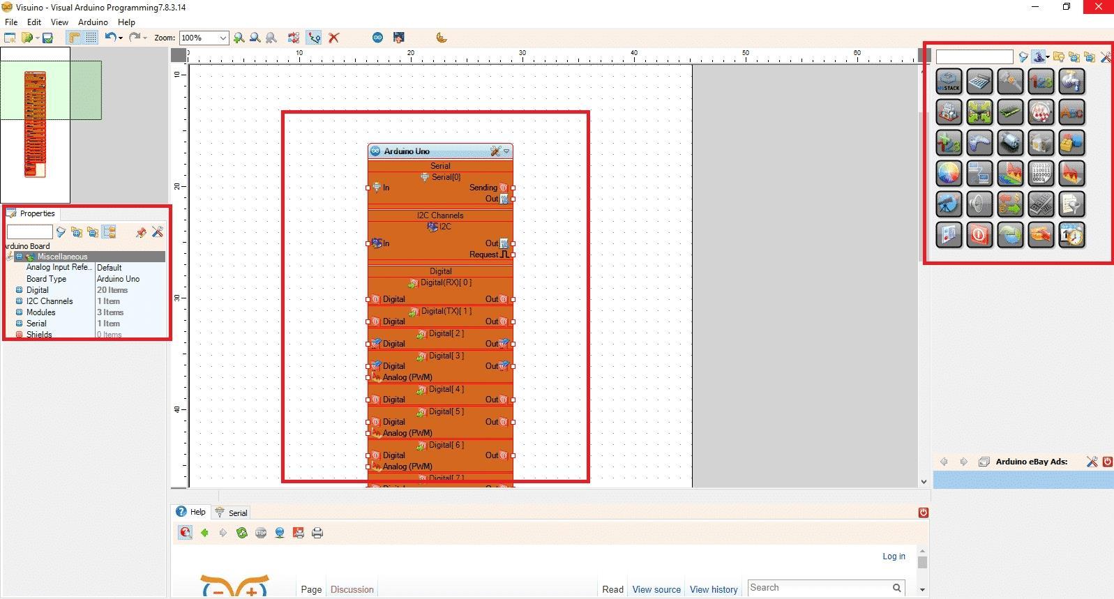
The setup is pretty straight forward. First we need to download and install the latest Arduino IDE. After that we can head over to Visuino and download it's latest version. After installing and launching Visuino, we will get an interface like in the image above.
- In the center we see the main block which represents the actual microcontroller.
- On the right side we find all the component blocks like Math, Logic, Digital, Analog and so on.
- On the left side we can edit the properties of selected component.
Selecting Board.
For this tutorial I have used Arduino Nano for demonstration purpose so I will change the main block to Arduino Nano. You can use UNO or any other Arduino board you have access to.
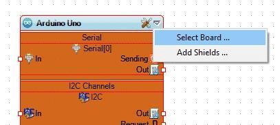
- To change the board, first click on the down arrow on the board and click on "Select board".
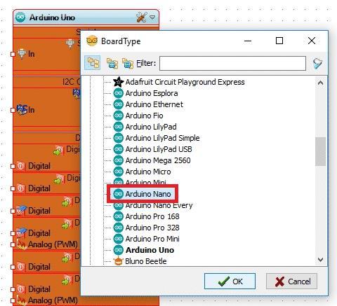
- From the list select the board you have, Here I have selected "Arduino Nano".
With that we are now all set to start using Visuino to make our first program.
Blink in Visuino.
As always we will test this setup with good old blink code. We will see how easy it is to blink an LED with Visuino.
Follow the steps given below and refer to the images for better understanding.
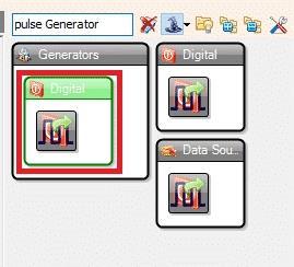
1. First from the right components menu we will search for "Pulse Generator".
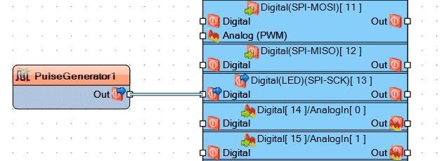
2. Drag the "Digital pulse generator" in the work area.
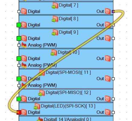
We will connect this component to pin number 13 of our board as it is connected to the on-board LED.
To connect the component:
3. Click and hold on the square contact point and click on the Digital pin 13 contact.
And that's it, we have the blink example ready. By default the frequency of the Pulse Generator is 1. i.e the LED will turn on for a second and off for a second.
Now we have to connect our board to the computer via USB and upload the code.
To open the code in Arduino IDE, we just have to press "F9" on the keyboard. Alternatively we can also click on the Arduino icon on the top menu bar. This will open the code in Arduino IDE and you can read and edit the code here. And upload it by connecting the arduino to your computer via USB cable and clicking the upload button.
Turn ON LED With a Push Button.
1. Click on the "Pulse Generator" and press Delete on your keyboard as we no longer need it.
2. Next connect output of any digital pin to the input of pin 13.
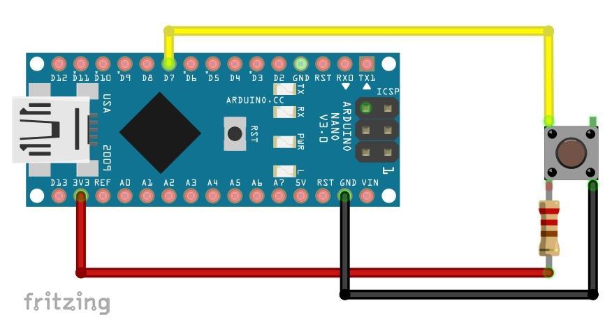
For example, I have used pin 7 for the pushbutton so I will connect the Output of pin 7 to Input of pin 13 (Refer the image above).
That's pretty much it, now press 'F9' on the keyboard and the code will open in IDE. Upload the code to Arduino. But first connect a pushbutton to pin 7. Use a resistor in range of 220ohm to 10K ohm.
Now you will notice that the on board LED stays on and turn off when the button is pressed. But we want the opposite results, i.e the LED should turn on when the push button is pressed. To achieve that we just have to invert the output of pin 7, to do that we will add an inverter in between the connection.
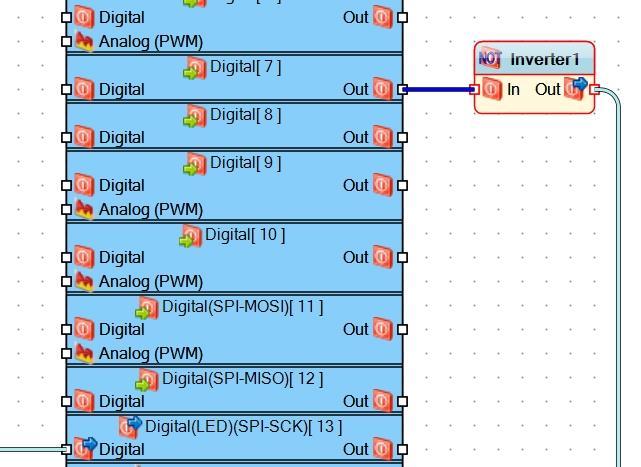
In the component's field search for 'inverter' and drag to the canvas. Next connect the output to the input of Inverter component and connect the Output of Invert component to the Input of pin 13 as shown in the image above.
This component will invert the output of pin 7, so High will come out as Low and vise versa. Now press F9 and upload the code. Now you will see that pressing the button lights up the LED.
Conclusion.
This article was just an introduction to Visuino. Now that you are familiar with the software and have an idea of how to use it, you can start experimenting yourself.
In future we will see more complex projects using this amazing software.
While you are here check out my website: ProjectHub.in There I post blogs and provide custom projects.