Introduction to Turning
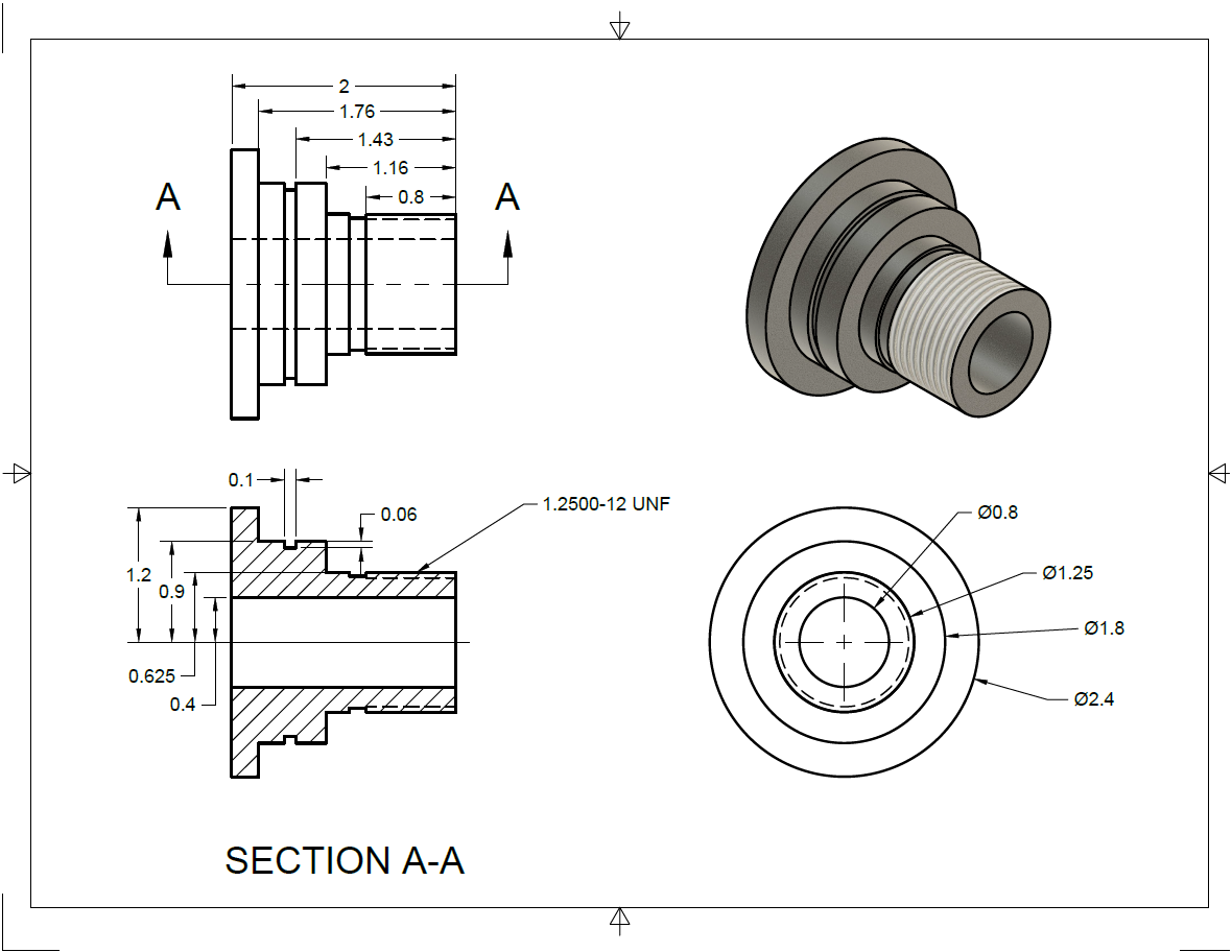
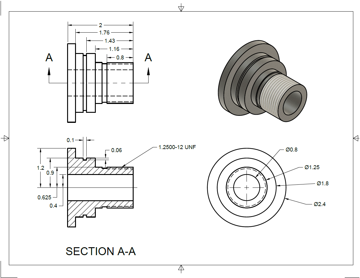
In this lesson, we will be programming a part for a two-axis lathe, starting from an engineering drawing. However, before we jump right in to programming this part, we will first take an look at the workflow of programming parts in FeatureCAM. This workflow will help guide us through the programming of every part in FeatureCAM, whether it is one of the parts shown in this class, or your own part in your shop.
Introduction to the Workflow

Whether you are new to FeatureCAM, or new to CAM in general, this class will help you build a solid FeatureCAM foundation by focusing on the fundamental workflow in FeatureCAM. In this class, we will program three different parts. While each part may be different, the workflow we follow to program them will remain the same. After completing this class, you will be able to use the workflow outlined in this class to tackle any project you may encounter in your shop. Whether you are programming a part on a 2-axis lathe, or a more complex part to be machine on a live tooling lathe with multiple spindles, following this workflow will help ensure you are able to complete your projects as quickly and efficiently as possible.

- Open/Import: Open a new FeatureCAM File, or import an existing solid model
- Stock: Specify size and shape of stock material you will be machining
- Machining Prep: Take into account real-world machining considerations such as touch-off points, tool cribs, and post-processors for your given machine to prepare your model for actual machining
- Create Features: Create all features needed to machine your final part
- Simulate: Simulate your toolpath to generate NC code, ensuring that your toolpath is as safe and efficient as possible
- Revise: Make any revisions necessary to further improve your toolpath, and re-simulate to verify new changes
Open, Stock, Machining Prep

- Open a new document
- Turn/Mill Setup
- Inch
- Wizard
- My Configuration
Once the document is created, and you are met with the Stock Wizard, you are free to move on to the next step in our Workflow – Stock. This is where we define the piece of material we are machining our part from.
- Define the piece of material that we will be machining our part from
- Round stock shape
- OD: 3"
- Length: 3"
- ID: 0"
- Material: Aluminum
- No Multi-Axis
After defining the piece of material we will be using as our stock, the wizard will ask us to define our setup location, or touch-off point. At this point, we are ready to move on to our next step – Machining Prep.
- On the 'Setup – Definition' leave the default parameters for this part
- Align the setup, or tough-off point, with the stock face
- Offset the setup in the z axis by -0.03”, we want the setup to be aligned with the part rather than the stock
- Press Finish

Now that we have completely worked through the import wizard, we are just a few short steps away from finishing with our machining preparation.
- Select the ‘basic’ tool crib
- Select the Turn Post 1 post-processor
Create Features

For this part, we will be working from an engineering drawing to create features using FeatureCAM’s sketching and dimensioning tools.
The first thing we are going to do, is take a look at our drawing, and identify the different features which we are going to machine.
- A turned profile
- An outer diameter groove
- A bore
- An external thread
Now that we know which features we are going to be creating, let’s construct geometry to define them.
- Use the ‘Connected Line' line constructor
 to
sketch an outer profile of the part, this will be used to create the turning
feature.

- Now use the '2 Points' line constructor
 to create a single line to define the outer diameter of the
bore.

- Use the ‘Connected Line' line constructor
 to
sketch the cross section of the groove.

Now that our geometry is created, we can use it to create curves which in turn can be used to create features. Curves are placed over the top of geometry and the two remain separate objects.
- Use the ‘Pick Pieces’ curve chaining tool
 to chain
three separate curves, one for the turning profile, one for the bore and one
for the groove.
- Create a Turn Feature from curves
- Select curve 1
- Press Finish to keep all defaults
- Create a Bore Feature from curves
- Create a Groove Feature from curves.
- Select curve 3
- Press Finish to keep all defaults
- Create a Thread Feature from dimensions
- Standard Thread 1.2500-12 UNF
- Thread Length 0.8”
- Z location 0
- Relief groove length 0.15”
- Finish
- In the Strategies tab tick the Finish box
- Turn on Chamfer
- Depth 0.05
- Press Apply and then OK
- Create a Face feature from dimensions
- Thickness 0.75
- Inner Diameter 0
- Outer Diameter 3”
- Press Next
- Position at Z = 0
- Press Finish
Note that the face feature is automatically moved to the top of the operations list. FeatureCAM has made a smart choice to help reduce programming time. If we want to change the order of any of our features, we can simply click and drag €them to change their position.
When you are done, your features should look similar to the features shown below.

With all the features needed to machine this part created, we are ready to simulate our results, and revise from there.
Simulate, Revise

Now, let's simulate the Features we just created, make any necessary changes, and simulate our final code.
- Run a Centerline Simulation
- Run a 3D Simulation
We are getting a gouge during the bore feature, if we run just this feature and slow the simulation speed down, we can see that our boring tool is far too large to fit inside the hole. We need to create a new tool which will be able to machine this feature.
- Open the Tool Manager
- Change the Tool Group to ‘Lathe – Boring’
- Double click on the WN_B_Small_80_RH tool to edit it
- Change the name to ¼” Bore Bar
- Tip radius 0.02”
- Inscribe circle diameter 0.1875”
- Open the Holder tab
- Shaft Diameter 0.25”
- Length 6”
- Exposed length 6”
- Min diameter 0.3125”
- Press OK and then OK again
- Create new tool
- Open the bore 1 properties window
- Select the Rough operation
- Check the box next to ¼” Bore Bar
- Apply and then OK
- Run a 3D Simulation
We should add a Cutoff to clear away the excess stock at the back of the part. We should also extend our turn and bore features slightly beyond the Cutoff to ensure a clean finish.
- Create a Cutoff Feature from dimensions
- Diameter 2.4”
- Inner Diameter 0.75”
- Chamfer 0.03
- Width 0.25”
- Set the Z position to -2”
- Press Finish
- Extend curve 1 so that it passes all the way through the Cutoff Feature
- Do the same for curve 2
- Extend the Bore pre-drill to the length of the new curve

- Run a 3D Simulation
Everything is now looking good, but let's make a few small changes to our turning and boring operations. FeatureCAM has automatically populated parameters such as feeds, speeds and depth of cut based on our choice of material and machine configuration. It has also automatically selected the tools in our library which it believes to be most appropriate.
All of these values remain fully customizable however, so let’s go into our boring operation and change the depth of cut and finish allowance.
- Change the depth of cut and z finish allowance of the bore operation
- Double click on the bore 1 feature in the Part View to open it
- Click on the Rough operation to open the roughing options
- Open the Boring tab
- Change the depth of cut to 0.0325”
- Change the z finish allowance to 0.002”
- Press Set, Apply and then OK
In addition to changing values for individual operations, we also change the defaults for the whole document in the machining attributes.
- Click on Machining Attributes in the Features and Machining
- Expand the Turn tree and open the Turn/Bore tab
- Change the rough depth of cut to 0.0325”
- Change the z finish allowance to 0.002”
Go into the turn feature and you will see that the depth of cut and z finish allowance have been updated automatically. This will also apply to any new turn or boring features that we create.
- Run a 3D Simulation
With these revisions made, and our simulation verified, we are ready to move on to our final, and most important step – NC Code.
NC Code

With our final simulation run, our NC Code has been generated and is ready to be sent to the machine.
- Select the Show NC icon
 to open our NC code in the Results window.
- Select the Save NC
 icon to save the displayed code.
- Save the NC code to your desired directory.
Note: This exercise is for educational purposes. The post-processor used in this exercise is a generic post-processor used for training that will likely not work for your machine. Do not attempt to run any code generated in this exercise.