Introduction to Arduino
by Allison Fernandez in Circuits > Arduino
659 Views, 4 Favorites, 0 Comments
Introduction to Arduino
Have you ever wondered to make your own devices like weather station, car dashboard for monitoring fuel, speed and location tracking or controlling your home appliances controlled by smartphones or have you ever wondered about making sophisticated robots that can talk, walk and move its arms or what about making your own mp3 player devices, making fingerprint detection device, Automated plant watering system, earthquake sensor, walkie talkie or remote controlled CCTV cameras based surveillance system. If you have ever wondered and you are willing to put your contribution in digitizing the world then believe that you can make all the stuff that you want to create and then you must have to know some basic electronics and about microcontrollers. The microcontroller is a compact integrated circuit design that takes inputs from different sensors i.e. temperature sensor, motion detection sensor, range finding sensor, etc. and is programmed to get desired output from actuators i.e. led, motors, relays, etc. Knowing today’s open source world learning, understanding, and making such devices is not a difficult task with the great contribution of the Arduino community to the world it is accessible to every hobbyist and engineers around the globe.
Arduino is an open-source hardware and software platform for hobbyist and engineers to read inputs from different sensor, process those input and provide the desire output by actuating different actuators i.e. Basically you can say that Arduino can be a brain of many projects.
Types of Arduino
There are different types of Arduino boards with having
different numbers of analog, digital and PWM pin and the great thing is you can easily start working with any of them. Different Arduino additions are enlisted here.
● Arduino Uno
● Arduino Due
● Arduino Mega
● Arduino Leonardo Board
● Lillypad Arduino Board
Arduino Uno
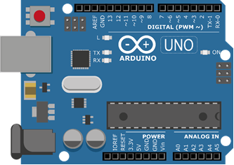
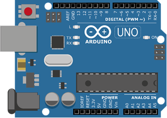
Most of the beginners get started using Arduino Uno, it is aboard that have main microcontroller ATMegga328 having memory of 2KB SRAM AND 32KB flash it has 14 Digital I/0 in which 6 are PWM and 6 are analog output pins. a reset button, a power jack, a USB connection and more. It includes everything required to hold up the microcontroller; simply attach it to a PC with the help of a USB cable and give the supply to get started with a AC-to-DC adapter or battery.
Arduino Due
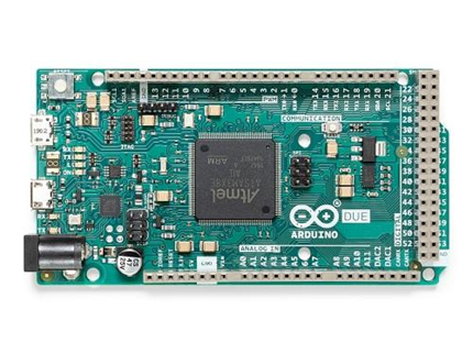
Arduino Due’s main microcontroller is AT91SAM38XE having memory of 96KB SRAM, 512KB flash consist of 54 digital pins in which 12 are PWM and have 16 analog input pins
Arduino Mega
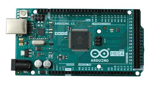
It contains ATmea2560 as microcontroller having memory of 8KB
SRAM and 256KB flash having 54 digital IO pins in which 12 are PWM and 16 analog input pins, a reset button, a power jack, a USB connection and a reset button. It includes everything required to hold up the microcontroller; simply attach it to a PC with the help of a USB cable and give the supply to get started with a AC-to-DC adapter or battery. The huge number of pins make this Arduino board very helpful for designing the projects that need a bunch of digital inputs or outputs like lots buttons.
Arduino Leonardo
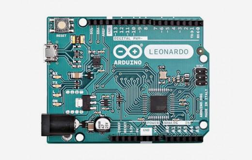
Its main microcontroller is ATmega32u4 having memory of 2.5KB SRAM and 32KB flash having 20 digital IO pins and 12 analog input pins. The first development board of an Arduino is the Leonardo board. This board uses one microcontroller along with the USB. That means, it can be very simple and cheap also. Because this board handles USB directly, program libraries are obtainable which let the Arduino board to follow a keyboard of the computer, mouse, etc.
LilyPad Arduino Board
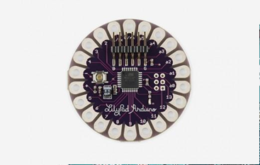
The Lily Pad Arduino board is a wearable e-textile technology Each board was imaginatively designed with huge connecting pads & a smooth back to let them to be sewn into clothing using conductive thread. This Arduino also comprises of I/O, power, and also sensor boards which are built especially for e-textiles. These are even washable!
Tools for Arduino Development Environment
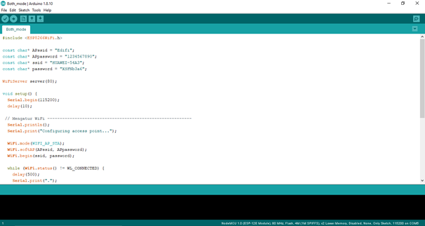
Arduino Programming Language:
Arduino is programmed in C++ which is used in different aspects of projects like software development but for Arduino C++ is used with additional functions. You can create Arduino sketch, Arduino sketch is the name given to the Arduino code file. You write the code in Arduino IDE. These sketches can be saved into the project folders and the IDE gives the option to compile C++ code into machine language and upload them into Arduino board.
Arduino IDE
Arduino IDE (Integrated Development Environment) is the C++ code editing, compiling and uploading tool where you can write your program to program IO pins for various purpose and you can use open-source libraries for writing sophisticated programs integrated with different function we will later on discuss in detail about libraries.
Arduino IDE Installation
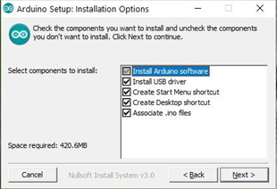
Step 1. Download Arduino IDE
Step 2. Wait until the download process complete.
Step 3. Install the software and choose the components that you want to install, as well as the install location.
Step 4. Accept driver installation when prompted by Windows 10
Installing Arduino Driver
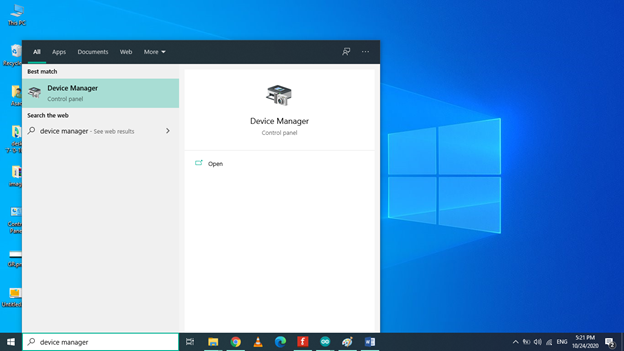
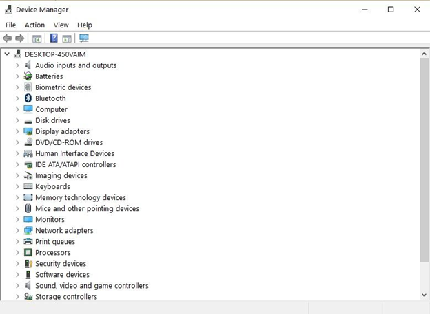
Go to Start->type Device Manager’>double click the first result to launch the Device Manager.
1. Go to Ports > locate the Arduino UNO port
2. In case you can’t find that port, go to Other Devices and locate Unknown Device
3. Select the Arduino UNO port > click on Update Driver.
4. Select the option ‘Browse my computer for Driver software’ > go to the Arduino software download location > select the arduino.inf file/Arduino UNO.inf (depending on your software version)
5. Wait until Windows finishes the driver install process.
Now that you installed the Arduino software and driver on your computer, it’s time to open your first sketch. Select your board type and port and upload a program to make sure that your board is up and running.
Graphical Representation of Arduino IDE
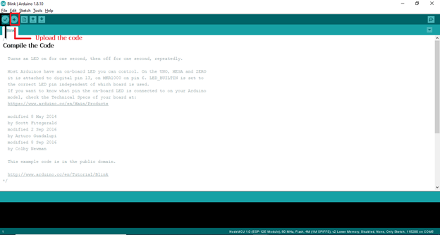
As Arduino IDE is used to edit, save, compile and upload the code into Arduino here is the graphical representation of Arduino IDE.
To Open a New File in Arduino IDE
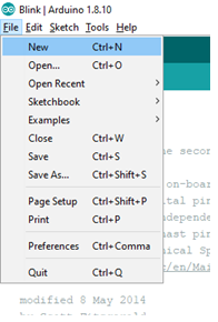
To open a new file click on file->new
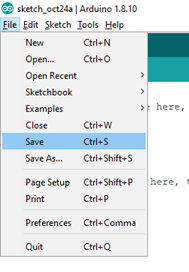
To Save Arduino Sketch
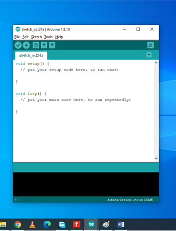

New file will be opened
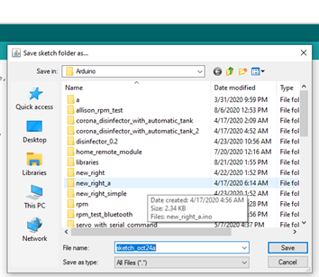
Step-1: To save the Arduino Sketch go to File-> save A window to save the sketch will be popped up
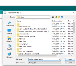
Step-2: Rename the Arduino Sketch and click the save button. The sketch will be saved.
Arduino Program’s Examples
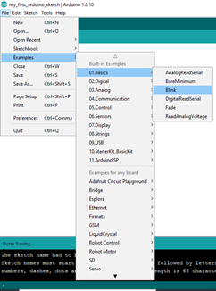
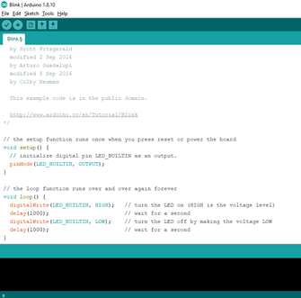
Arduino IDE includes many example program to learn and make projects from them these examples are about blink a led, analog and digital input output, serial communication, sensor, etc.
To open led blink example program click on File->Example->Basics->Blink
Arduino Libraries
According to Arduino community “Libraries are a collection of code that makes it easy for you to connect to a sensor, display, module, etc. For example, the built-in LiquidCrystal library makes it easy to talk to character LCD displays. There are hundreds of additional libraries available on the Internet for download”. Libraries includes common methods and function such as device drivers or utility function using libraries it becomes easy to program without coding many lines you can use pre build functions for your program. There are variety of open-source libraries available on internet, Arduino IDE also provides libraries that are built by Arduino community such as library for controlling of servo motors, Ethernet, etc. Arduino IDE also provides option to install and use external libraries you can also make your own libraries and install them in Arduino IDE.
Arduino Library Installation Method
There are two method through which we can install library in Arduino IDE one is through Arduino IDE Library Manager and other is through using .zip file most of the libraries are available on Arduino Library manager but there are many libraries that developer make it by them selves and make them available on github so we have both option but we can use any of both.
Installation of Library Using Library Manager
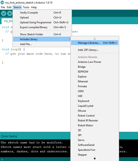
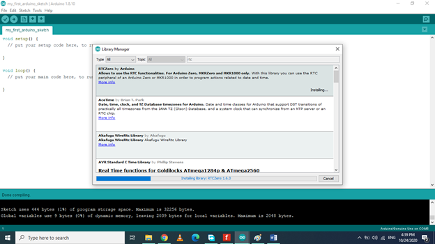
To install library using library manager click on sketch->include library->Manage libraries
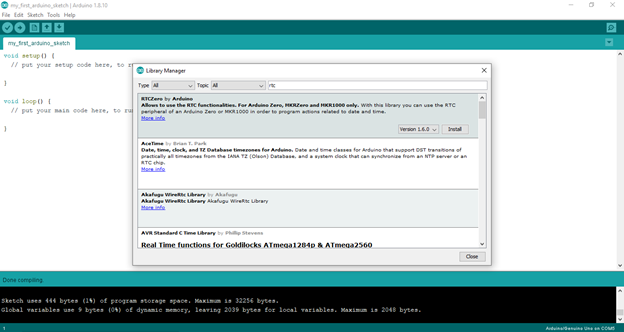
After this library manager will be opened here you can see
libraries that are already installed. In this example we will install RTCZero for this you have to search for RTCZero library when you find it choose its version and click on install button, the installation will be started.
Importing a .zip Library
Libraries are often distributed as a ZIP file or folder. The name of the folder is the name of the library. Inside the folder will be a .cpp file, a .h file and often a keywords.txt file, examples folder, and other files required by the library.
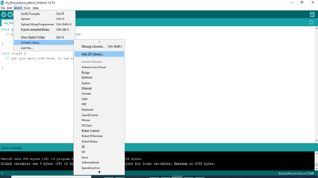
To install zip library click sketch->Include Library->Add .zip Library
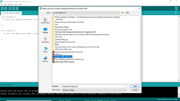
The Browse window will be open there set the location to where zip library is saved and click on open button.
Arduino IDE Shortcut Keys
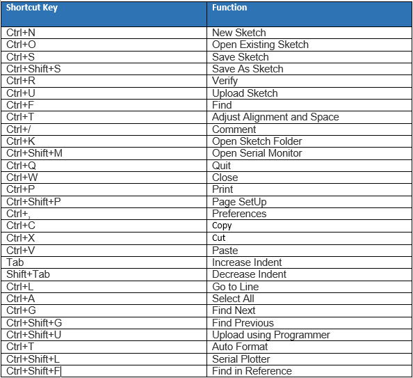
Arduino IDE has some short keys through which we can do different function like compiling, uploading saving etc.
Arduino’s IO Pins
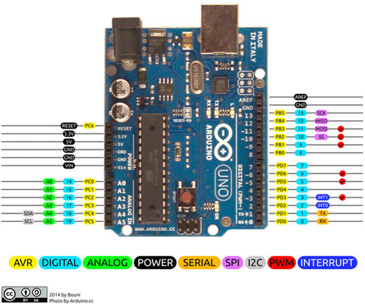
Arduino is a prototyping board that usually comes with different configuration of I/O (input/output) pins, the pins are either analog or digital pins,
Analog Pin.
Analog pins are actually input pins that are usually used to read physical data as input or it’s a pin that can read physical data from sensors, a sensor is a device that can convert physical energy to electrical energy. Arduino can read this electrical energy as an electrical signal using analog pins
Digital Pin.
The digital pin can be both INPUT and OUTPUT pin so as it is named it can read INPUT and write OUTPUT in digital form. The digital data is in the form of HIGH or LOW where HIGH means ON and LOW means OFF for example if led is attached to Arduino’s digital pins and you program this pin to be HIGH eventually the led will get ON and by programming it to get LOW the led will get OFF.
Pulse Width Modulation Pins.
Some of the digital pins in Arduino have additional functionality of providing Analog Output and the are called as PWM pins, the function of PWM pins is to write OUTPUT in range of level between HIGH and LOW levels, let’s suppose led is connected to PWM pin and you want to control the brightness of led or motor is attached to PWM pin and you want to control the speed of motor you can assign the value from 0-255 to control the brightness or speed.
Arduino LED Blink Program
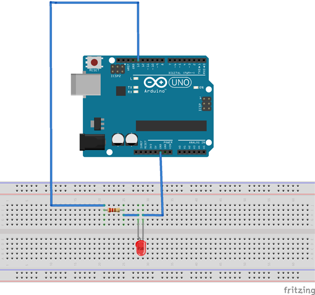
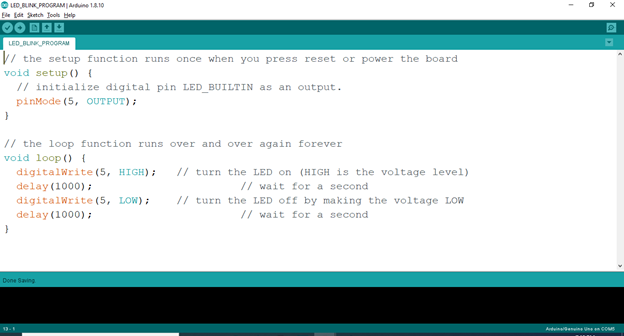
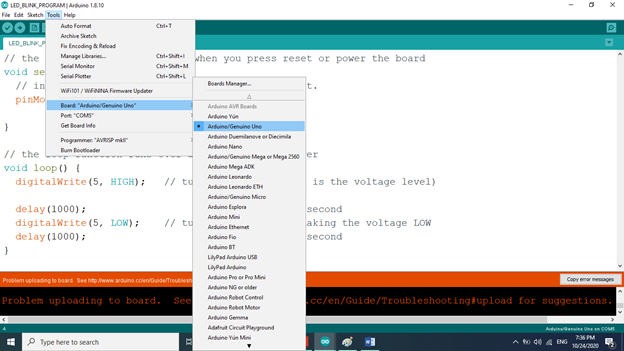
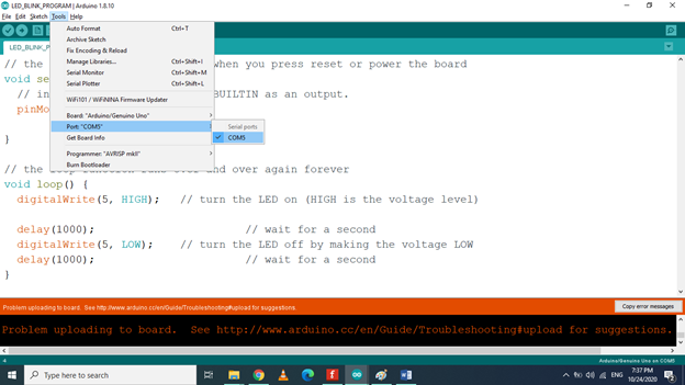
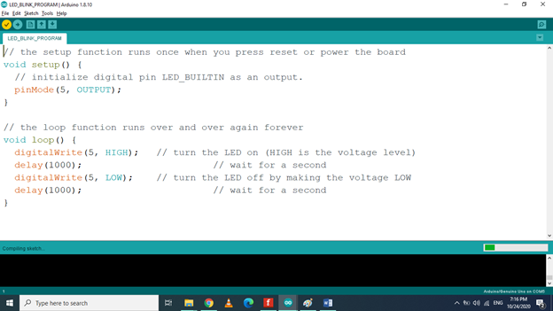
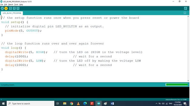
As Arduino IDE and driver are installed connect to program
Arduino to blink an LED components are required that are mentioned below
Components Used for LED Blink Project
● Arduino Uno
● USB Cable Type A/B
● 220 Ohm Resistor
● LED
● Breadboard
Schematic
Connect Arduino Uno’s pin 5 to 220 ohm resistor and connect other pin of resistor to Led’s anode (+) pin and connect Arduino Uno’s GND pin to LED’s cathode (-) pin.
Writing Program to Blink an LED
Step 1. Open the Arduino IDE.
Step 2. Open a new sketch
Step 3. Save new sketch as LED BLINK PROGRAM and wite the program
Step 4. Select the Board by clicking Tools->Board:-> Arduino Uno
Step 5. Select the COM port by clicking Tools->Port
Step 6. Click on Compile Button
Step 7. Wait for compilation to be completed then click on Upload button
You will see the message “Done Uploading” as you see this message the led connected on pin 5 of Arduino will seems blinking after a second.
Serial Monitor
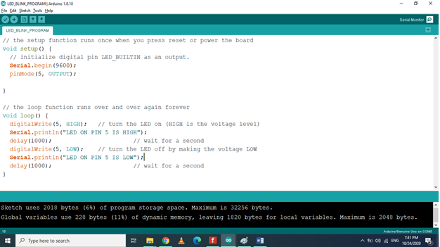
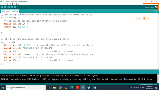
The Arduino IDE has a feature that can be a great help in debugging sketches or controlling Arduino from your computer's keyboard. The Serial Monitor is a separate pop-up window that acts as a separate terminal that communicates by receiving and sending Serial Data.
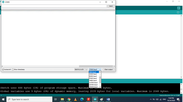
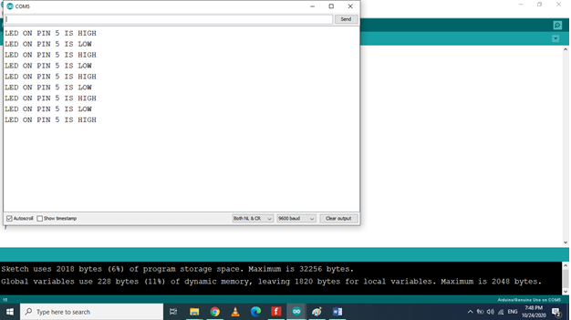
You can modify the led blink program to see the status of LED connected on pin 5 of Arduino is either HIGH or LOW on your computer using Arduino IDE’s serial monitor using the serial communication capability of Arduino, for doing this first you have to setup the serial baudrate to 9600 baud rate is simply defined as transmission speed of data from Arduino to computer or vice versa in terms of bit per second so setting baud rate to 9600 is like transmission speed is 9600 bits per second.
Writing Program to Blink an LED
Step 1. Open the Arduino IDE.
Step 2. Open a new sketch
Step 3. Save new sketch as LED BLINK PROGRAM and write the program
Step 4. Select the Board by clicking Tools->Board:->Arduino Uno
Step 5. Select the COM port by clicking Tools->Port
Step 6. Click on Compile Button
Step 7. Wait for compilation to be completed then click on Upload button
Step 8. Open the Serial Monitor by pressing Ctrl+Shift+m or by clicking on upper right corner.
Step 9. Set Baud Rate of Serial Monitor as both Arduino and Computer must have same baud rate for serial communication.
Here you will see as soon as the LED get HIGH or LOW the message is printed serially on Serial monitor