Rover IoT | Intel IoT Road Show 2015
by DouglasE1 in Circuits > Wearables
1489 Views, 8 Favorites, 0 Comments
Rover IoT | Intel IoT Road Show 2015
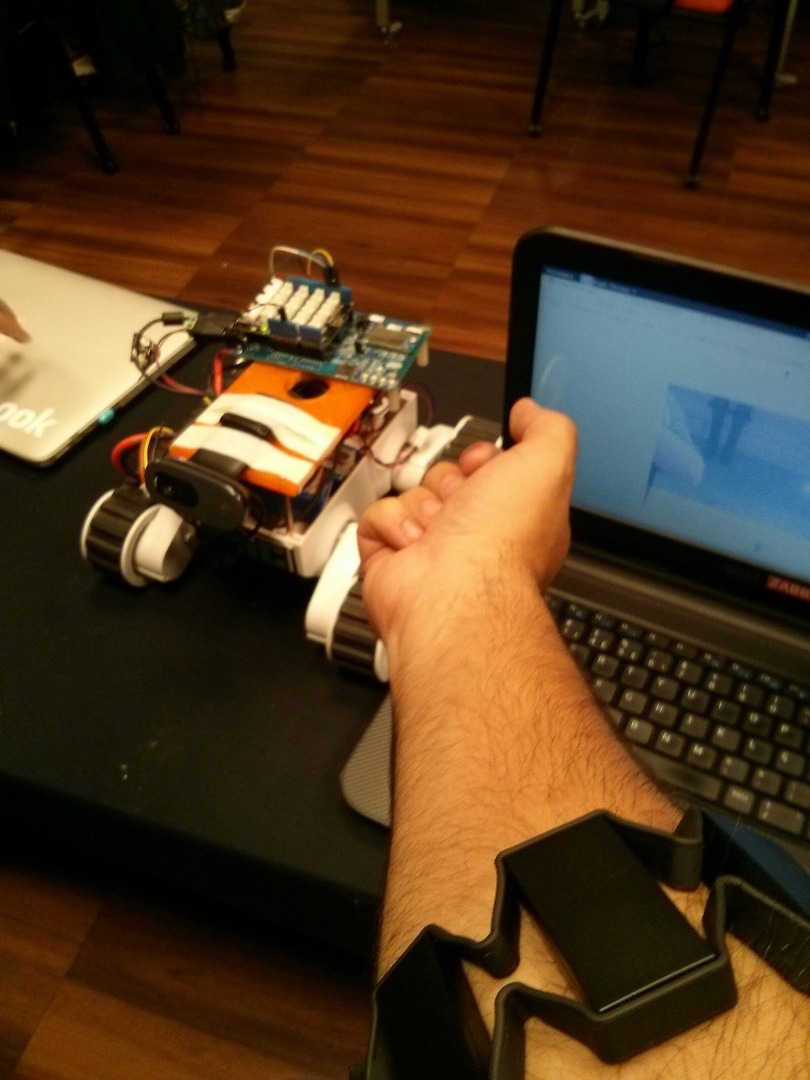
Hi friends,
my name is Douglas Esteves and I'm a enthusiastic with the resources in the Intel Edison .
My friend Gilvan Vieira and I developed a project in Event Intel IoT Road Show 2015 (November 6-7) in São Paulo, Brazil.
The idea the project is to control the robot in a different way, using a Myo armband to control wirelessly the robot movements over the internet.
tips : Step webcam configuration used this link https://github.com/drejkim/edi-cam
Equipaments used:
- Intel Edison
- Rover 5 chassis
- Drive Motor L298H
- Batery Lipo 220mAh
- Jumpers
- Router (internet)
- Myo Armband Webcam
Step 1 : Start Intel Edison and WebCam
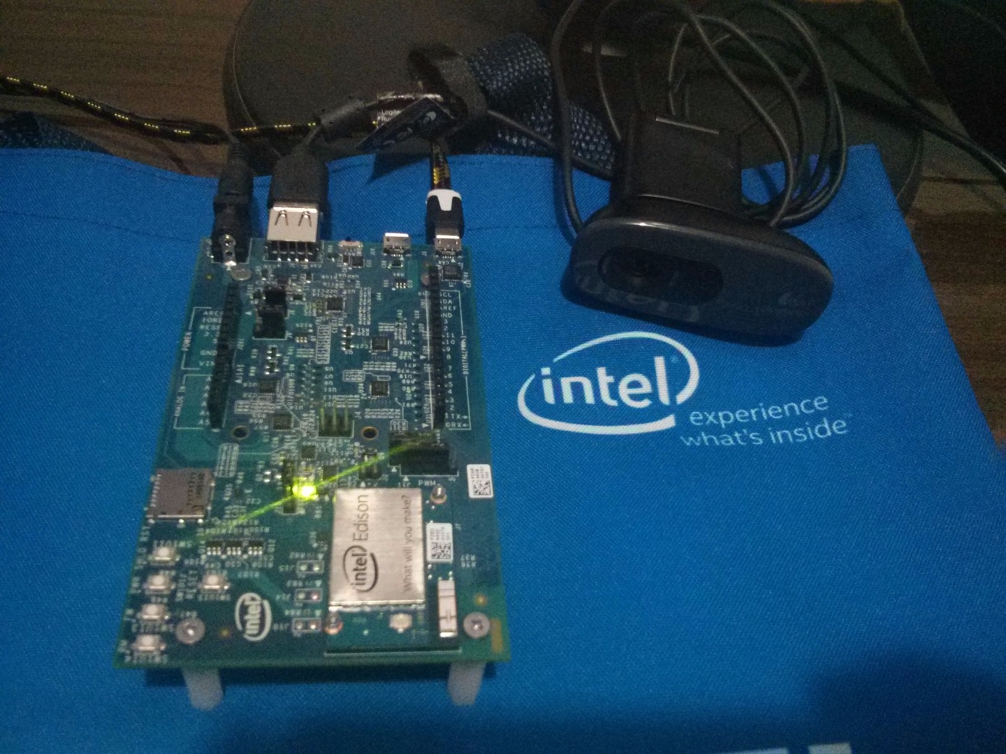
Turn On your Intel Edison for procediments basic :
Conect cable micro USB.
Open Terminal Linux. (gnome-terminal my laptop)
gnome-terminal
Install screen (Debian $apt-get install screen)
screen /dev/ttyUSB0 115200
Press Enter case your screen is black
User : root
Password: "null"
Configure IP.
configure_edison --wifi
select your wifi and enter password.
after write command
ifconfig
About this link Edi-cam
Use webcam more Intel Edison, Node.Js and WebSockets. (Does not transmit song) listening for the incoming video stream via HTTPm ffmpeg...
Use webcam UVC-Compatible .
Configure repository
vi /etc/opkg/base-feeds.conf
include
src/gz all http://repo.opkg.net/edison/repo/all src/gz edison http://repo.opkg.net/edison/repo/edisonsrc/gz core2-32 http://repo.opkg.net/edison/repo/core2-32
before opkg update
opkg install git
git clone
git clone https://github.com/drejkim/edi-cam>
example for link edi-cam Check whether or no the UVC drive is installed.
find /lib/modules/* -name 'uvc'
/lib/modules/3.10.17-poky-edison+/kernel/drivers/media/usb/uvc
lsmod | grep uvc <br>
uvcvideo 71516 0
videobuf2_vmalloc 13003 1
uvcvideo
videobuf2_core 37707 1uvcvideo
Install ffmeg
cd /edi-cam/bin
./install_ffmpeg.sh
Install Nose.js
cd ../web/server
npm install
modify file.
vi web/client/index.html
var wsUrl = 'ws://ip:8084'
I used this link (Tank's Esther Jun Kim) : https://github.com/drejkim/edi-cam
Step 2 : H Bridge
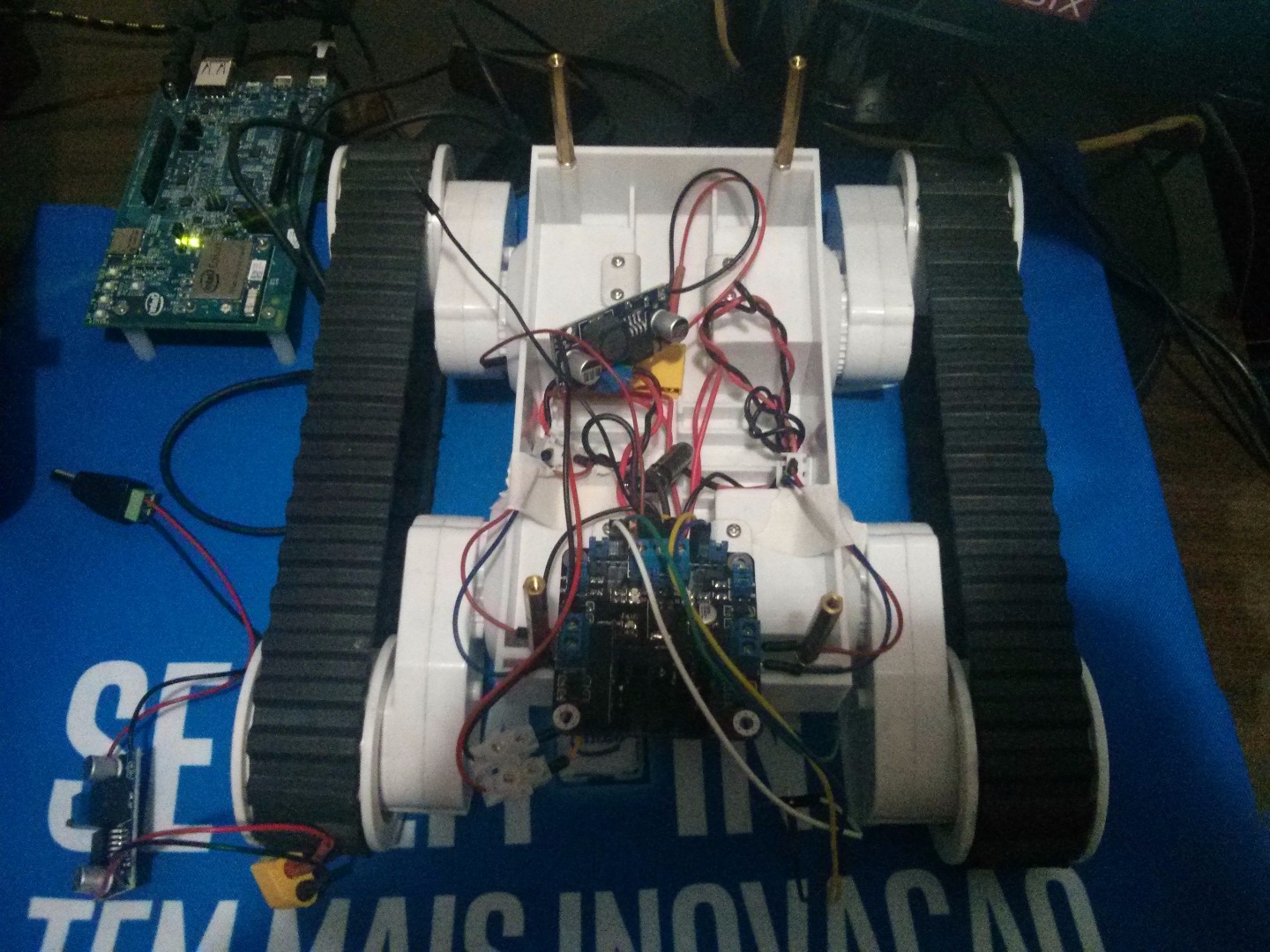
Chassi Rover 5
Two Motors
DC-DC
LM2596S DC-DC
Battery
Turnigy 2200mah 3s 20-30c 11.1v
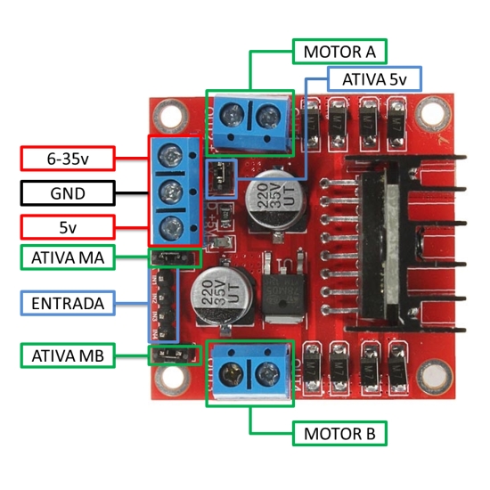
H Bridge L298N (pinout)
5v + ENA : board jumpers enable
IN1  : 3
IN2  : 4
5V + ENB : board jumpers enable
IN3  : 5
IN4  : 6
R1   : board jumpers enable
R2   : board jumpers enable
R3   : board jumpers enable
R4   : board jumpers enabl
VCC  : LM2596S DC-DC
5V   : Intel Edison board.
GND  : Intel Edison Board and LM2596S DC-DC</p>
Step 3 : Program Rover
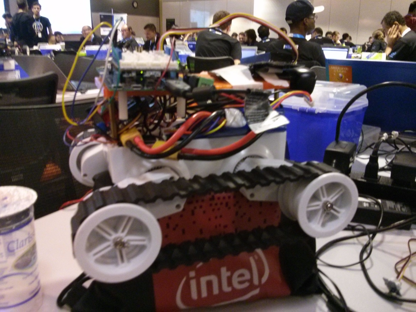
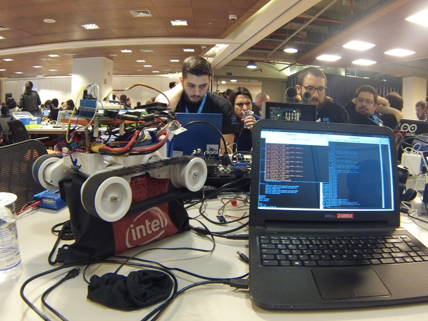
Simples program .
simples server UDP, commands for movimentar robot.
my laptop program, commands for robot.
Step 4 : Gesture Control Armband.
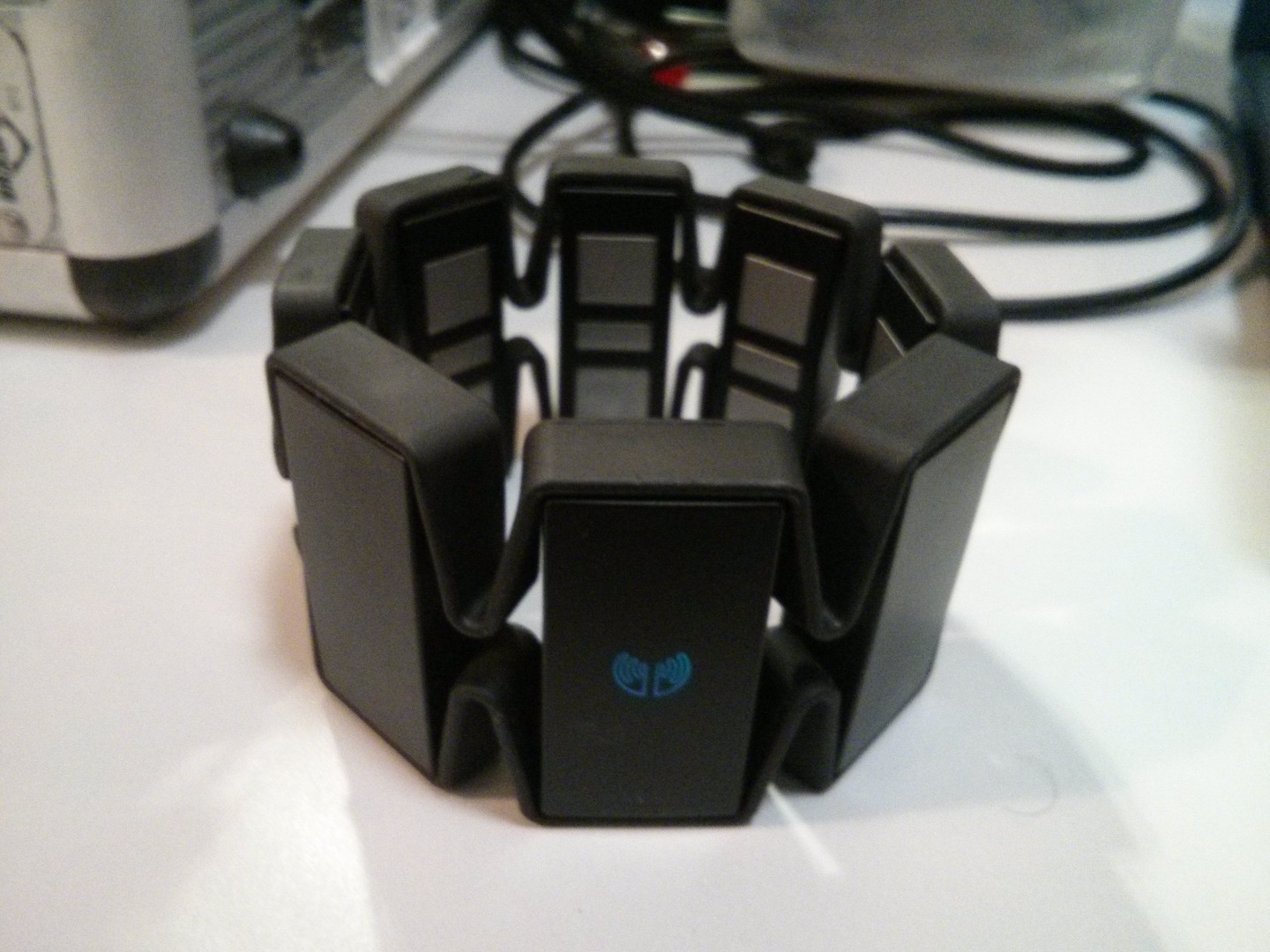
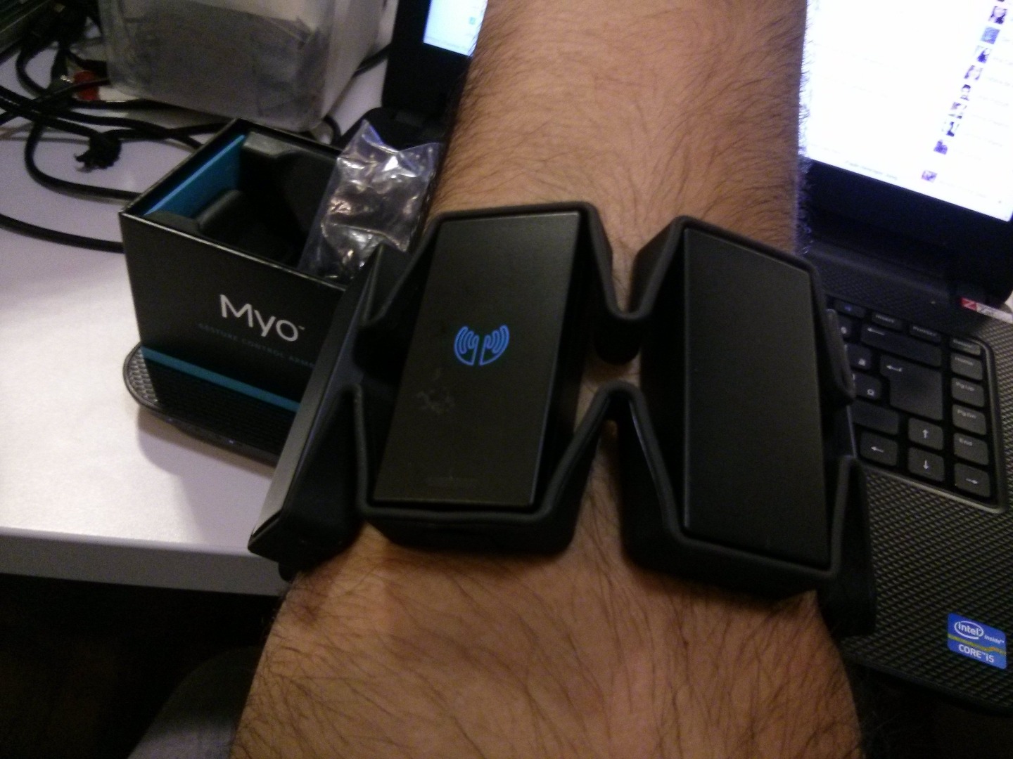
Data Transmission Function To The Myo
In this project we used a macbook with the operating system OSX El Capitan to send the data to the Intel Edison through UDP messaging. For this, we downloaded the SDK Myo in https://developer.thalmic.com/downloadshttps://developer.thalmic.com/downloads and compile the hello-
myo.xcodeproj project within thesamples folder of the SDK.
In this example we modify the code hello-myo.cpp file in the print () function of the DataCollectorclass. In this role we have access to the name of the activated gesture at that moment in Myo. With this data in hand we formatted the UDP messages and sent over the network.
The file add the following code beginning with the declaration of variables and inclusion of libraries:
#include <arpa/inet.h>
#include <sys/socket.h>
#include <unistd.h>
// here goes the ip address of the Intel Ediso #define SERVER "192.168.1.101" #define BUFLEN 1024 /// here goes the port that are you using #define PORT 21567</p><p>void die(char *s) { perror(s); exit(1); } struct sockaddr_in si_other; int s, i, slen=sizeof(si_other); char buf[BUFLEN]; char message[BUFLEN];
After that we add the code to discover the gesture detected, format and send the message to the Python code running in the Intel Edison.
if(poseString == "fist")
{

    std::string action = "STOP_MOVE";
    std::cout << action << "; " << lastCommand;
    lastCommand = action;

   if (sendto(s, action.c_str(), strlen(action.c_str()) , 0 , (struct sockaddr *) &si_other, slen)==-1)
    {
        die("sendto()");
    }
}
else if(poseString == "fingersSpread")
{
    std::string action = "MOVE_FORWARD";
    std::cout << action << "; " << lastCommand;
    lastCommand = action;</p><p>    if (sendto(s, action.c_str(), strlen(action.c_str()) , 0 , (struct sockaddr *) &si_other, slen)==-1)
    {
        die("sendto()");
    }
}
// there is more code in the .cpp file</p>
Just simply replace the code in print() function by the code in MyoSdkSenderFunction.cpp file.
Step 5 : Running Software and Testing
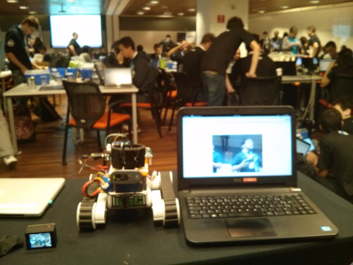
Running node server.js
and myo_server.py
after used Gesture control armband.