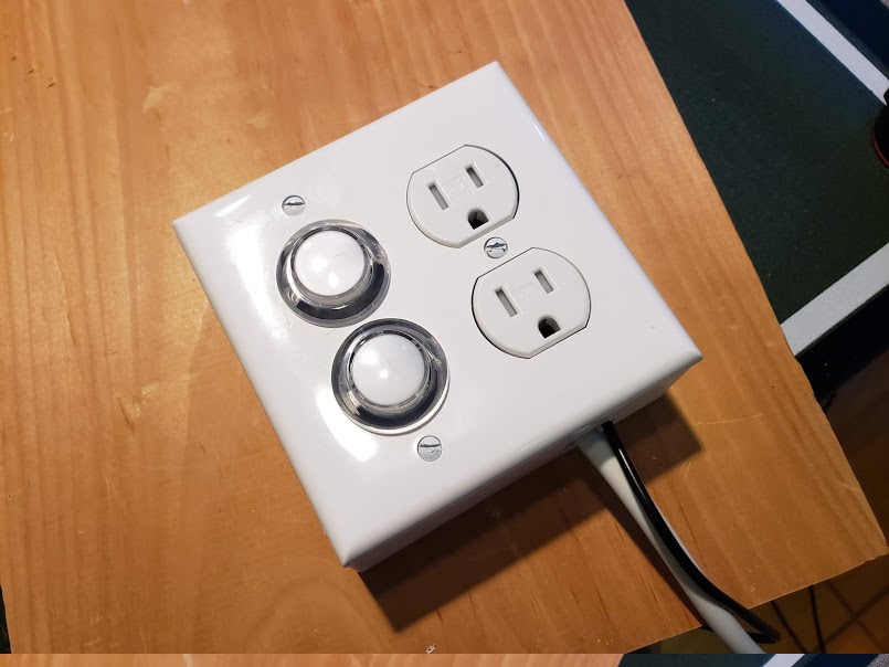
Internet Enabled Power Outlet
by khinds10 in Circuits > Raspberry Pi
2712 Views, 20 Favorites, 0 Comments
Internet Enabled Power Outlet
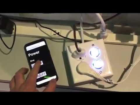
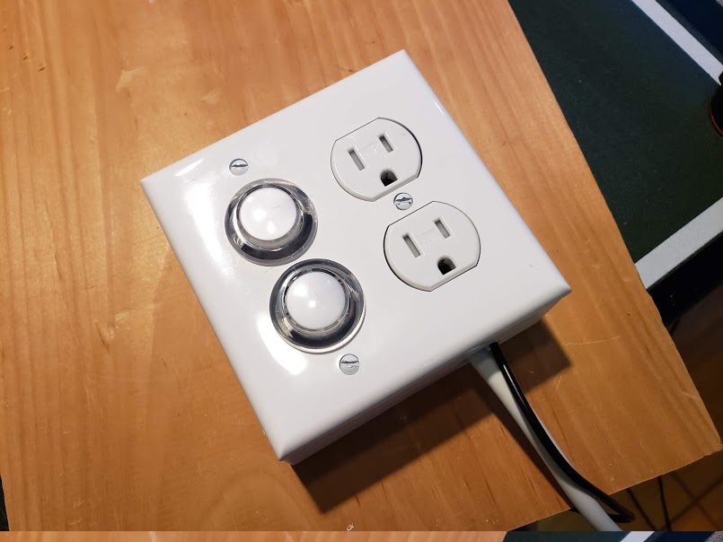
PowerHub Webserver Project & Internet Enabled Outlet Setup Instructions
Central data persistence hub for Internet enabled light and outlets in your home!
PowerHub Webserver Project & Internet Enabled Outlet Setup Instructions
Central data persistence hub for Internet enabled light and outlets in your home
Flashing RaspberriPi Hard Disk / Install Required Software (Using Ubuntu Linux) Download "RASPBIAN JESSIE LITE" https://www.raspberrypi.org/downloads/raspbian/
Create your new hard disk for DashboardPI
Insert the microSD to your computer via USB adapter and create the disk image using the dd command
Locate your inserted microSD card via the df -h command, unmount it and create the disk image with the disk copy dd command
$ df -h /dev/sdb1 7.4G 32K 7.4G 1% /media/XXX/1234-5678
$ umount /dev/sdb1
Caution: be sure the command is completely accurate, you can damage other disks with this command
if=location of RASPBIAN JESSIE LITE image file of=location of your microSD card
$ sudo dd bs=4M if=/path/to/raspbian-jessie-lite.img of=/dev/sdb (note: in this case, it's /dev/sdb, /dev/sdb1 was an existing factory partition on the microSD)
Setting up your RaspberriPi
Insert your new microSD card to the raspberrypi and power it on with a monitor connected to the HDMI port
Login
user: pi pass: raspberry
Change your account password for security
sudo passwd pi
Enable RaspberriPi Advanced Options
sudo raspi-config
Choose: 1 Expand File System
9 Advanced Options
A2 Hostname change it to "WIFI-OUTLET"
A4 SSH Enable SSH Server
A7 I2C Enable i2c interface
Enable the English/US Keyboard
sudo nano /etc/default/keyboard
Change the following line: XKBLAYOUT="us"
Reboot PI for Keyboard layout changes / file system resizing to take effect
$ sudo shutdown -r now
Auto-Connect to your WiFi
sudo nano /etc/wpa_supplicant/wpa_supplicant.conf
Add the following lines to have your raspberrypi automatically connect to your home WiFi (if your wireless network is named "linksys" for example, in the following example)
network={ ssid="linksys" psk="WIRELESS PASSWORD HERE" } Reboot PI to connect to WiFi network
$ sudo shutdown -r now
Now that your PI is finally on the local network, you can login remotely to it via SSH. But first you need to get the IP address it currently has.
$ ifconfig Look for "inet addr: 192.168.XXX.XXX" in the following command's output for your PI's IP Address
Go to another machine and login to your raspberrypi via ssh
$ ssh pi@192.168.XXX.XXX
Start Installing Required Packages
$ sudo apt-get update
$ sudo apt-get upgrade
$ sudo apt-get install vim git python-requests python-gpiozero python-smbus i2c-tools python-imaging python-smbus build-essential python-dev rpi.gpio python3 python3-pip libi2c-dev python3-spidev python-spidev
Update local timezone settings
$ sudo dpkg-reconfigure tzdata
select your timezone using the interface
Setup the simple directory l command [optional]
vi ~/.bashrc
add the following line:
alias l='ls -lh'
source ~/.bashrc
Fix VIM default syntax highlighting [optional]
sudo vi /etc/vim/vimrc
uncomment the following line:
syntax on
Install i2c Python Drivers
BUILD THE WEB API
The following instructions will allow you to build the central hub that explains to the various wifi enabled outlets and wall switches you may build, which devices are switched on and off. This is a small PHP script to place on a webhost of your choosing. It has the following API to get and set information to it. Note: don't forget to include the .htaccess file for proper URL routing to take place.
Install the "index.php", "values/" folder and settings.php (configured to your own values) to a PHP enabled webserver of your choice. The secret key value in the "settings.php" file must match the secret key value you would set in the "settings.py" file. This will on a basic level prevent any other web traffic from setting / writing values, turning on your devices, you now need this hashed API key in the HTTP request header to do so.
The API supports the following features, for this project we'll be using only the "flag" values which are boolean values that tell the switch to turn on and off. Perhaps if you wanted to take advantage of the "reading" values you could have it so if a room temperature gets too hot by saving a temperature there, it could turn on a window fan, etc.
Get the Code
Clone the following project from GitHub to get the code to run the webserver and the outlet RaspberryPI.
https://github.com/khinds10/PowerHub
API Endpoints when running on webserver
http://myhost/message (get the current message set)
http://myhost/message/set (HTTP POST a raw string value to this URL to set a new message)
http://myhost/flag/{id} (get the current boolean status of the flag by integer: {id})
http://myhost/flag/all (get all the current boolean status of all the flags as an array)
http://myhost/flag/{id}/set (set the current boolean status to 'true' for the flag by integer: {id})
http://myhost/flag/{id}/unset (set the current boolean status to 'false' for the flag by integer: {id})
http://myhost/reading/{id} (get the current averaged value for the reading by integer: {id})
http://myhost/reading/all (get the current averaged value for all the readings as an array)
http://myhost/reading/{id}/set (HTTP POST a raw numeric value to this URL to add a new value to the current calculated average) -- see below for how many values in total are compiled to the average value Configuation The 'readings' values are calculated as averages of a certain number of recent persisted reading numeric values. Set the following constant to how many of the most recent readings should be included to produce the average.
$readingsAverageLimit = 5;
Datastore Server will persist values to simple files located by naming conventions below. Note: {id} will be replaced by the real integer presented by the incoming request's URL.
$valueFileFolder = 'values' (name of the folder to contain the measurement files) $messageFileName = 'message.msg' (name of the message text file) $readingsFilesNames = 'reading{id}.avg' (name of the CSV averaged readings file) $flagFilesNames = 'flag{id}.flg' (name of the boolean flag value flag file)
Make sure all the value files are writable by the system
chmod 777 values/*
Supplies Needed



1 inch hole saw (for a drill)
5V 2 Channel Relay Module
Duplex Receptacle Wall Plate
Duplex Receptacle
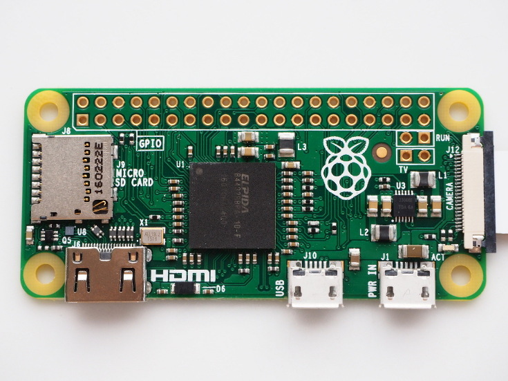
Pi Zero W
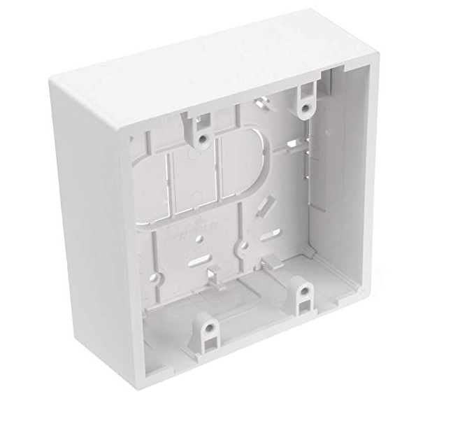
Surface Mount Backbox Dual Gang
White Illuminated Push Buttons
Building the Outlet
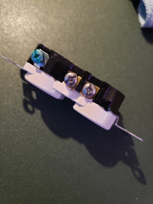
Break Outlet Tabs
Break the tab on the side of the outlet to have each socket turn on/off independently
Install Buttons
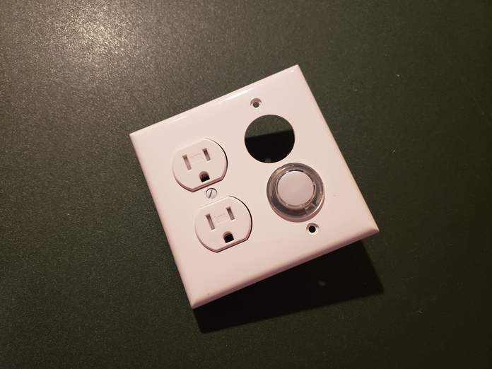
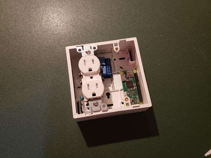
On the Outlet faceplate using the 1" hole saw cut 2 holes for the buttons to be placed next to the outlets
Test Sizing of components
Make sure all the components will fit in the outlet surface mount box
Wire Relay
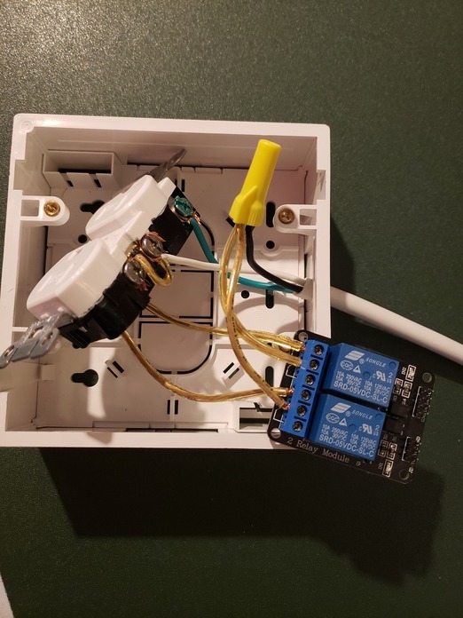
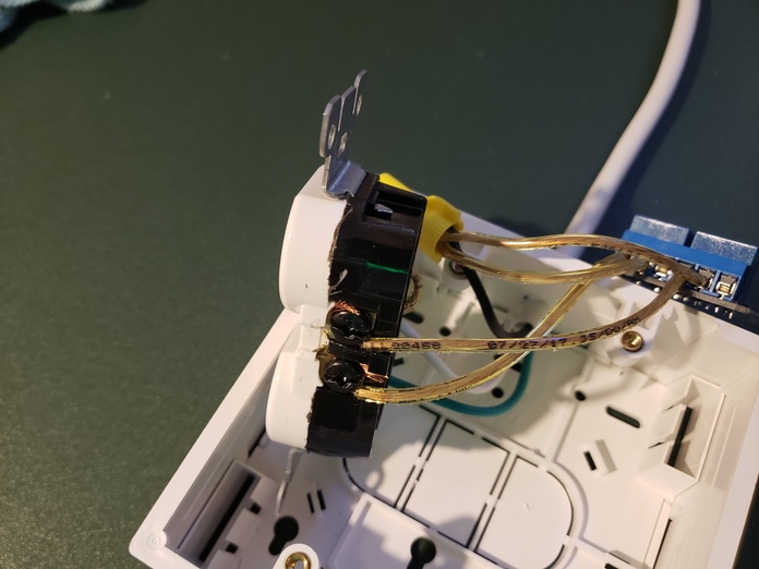
Wire the Relay to the outlet, from the extension cord going to the wall, connect the ground (green) and neutral (white) directly to the outlet
For the hot (black) connect them to the relay then from the relay to each outlet hot connectors individually
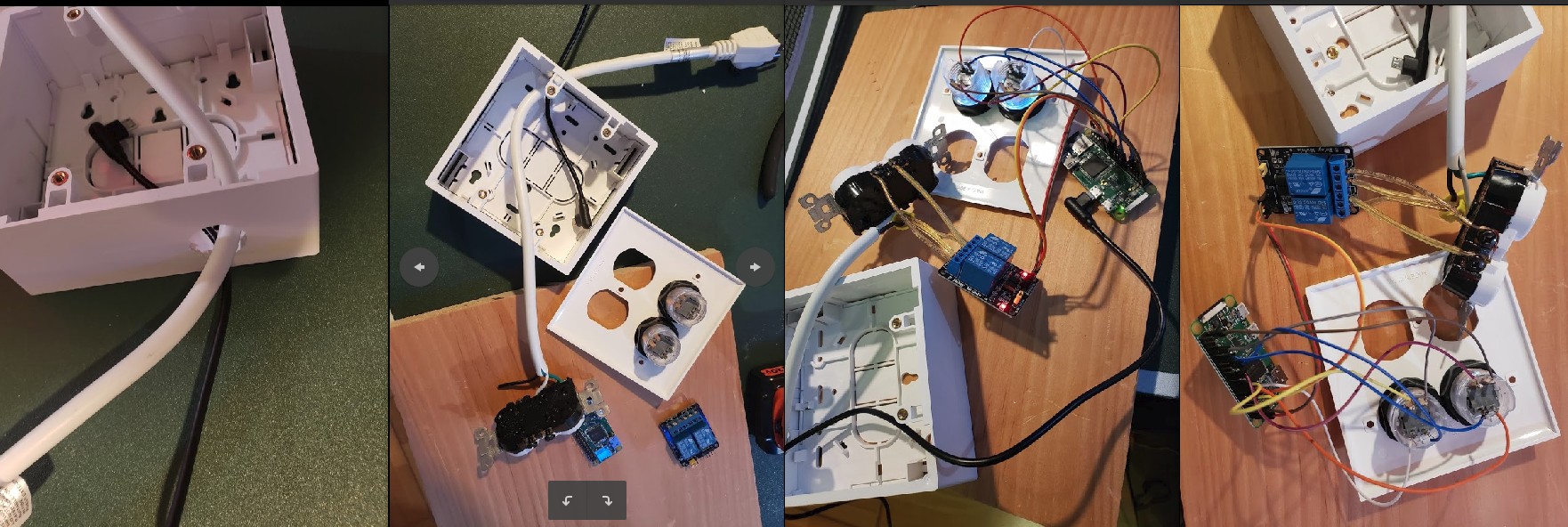
Additional Wiring and Assembly Images
Wiring Diagram
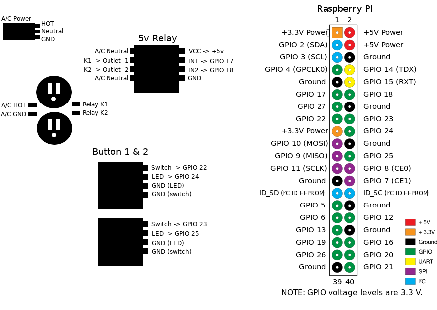
Use the diagram to correctly wire the components to work with the RaspberryPI Python code.
Test Dry Run
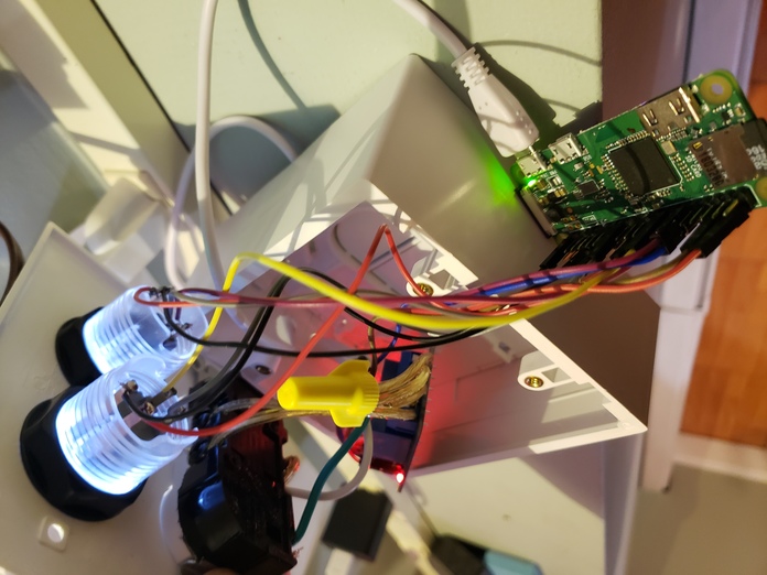
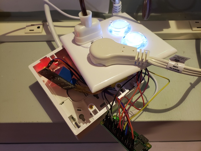
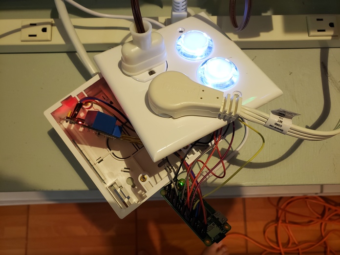
After final assembly before screwing the hole unit together, perform a dry run of the device to make sure there's no shorts, bad wiring
Set the Startup Scripts
crontab -e
add the following lines
@reboot python /home/pi/PowerHub/device/outlet/buttons.py
@reboot python /home/pi/PowerHub/device/outlet/relay.py
Finished!
