Internet Controlled LED Using NodeMCU
by Chirag_Modi in Circuits > Wireless
113706 Views, 34 Favorites, 0 Comments
Internet Controlled LED Using NodeMCU
The Internet of Things (IoT) is a system of interrelated computing devices, mechanical and digital machines, objects, animals or people that are provided with unique identifiers and the ability to transfer data over a network without requiring human-to-human or human-to-computer interaction.
In this instructable, we'll be making a simple IoT project.Web page controlled LED using NodeMCU connected on a local network.
DESCRIPTION
NodeMCU is an open source IoT platform. It includes firmware which runs on the ESP8266 WiFi SoC from Espressif, and hardware which is based on the ESP-12 module. The term "NodeMcu" by default refers to the firmware rather than the dev kits. The firmware ESP8266 uses the Lua scripting language. It is based on the Lua project and built on the Espressif Non-OS SDK for ESP8266. It uses many open source projects, such as Lua-cjson and spiffs. LUA based interactive firmware for Expressif ESP8622 Wi-Fi SoC, as well as an open-source hardware board that contrary to the $3 ESP8266 Wi-Fi modules includes a CP2102 TTL to USB chip for programming and debugging, is breadboard-friendly, and can simply be powered via its micro USB port.
FEATURES
- Wi-Fi Module – ESP-12E module similar to the ESP-12 module but with 6 extra GPIOs.
- USB – micro USB port for power, programming and debugging
- Headers – 2x 2.54mm 15-pin header with access to GPIOs, SPI, UART, ADC, and power pinsMisc – Reset and Flash buttons
- Power – 5V via micro USB port
Materials Required
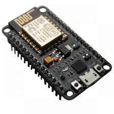
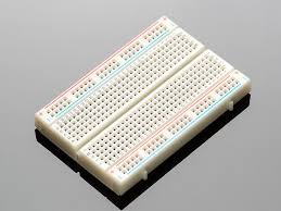
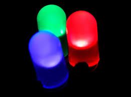
- ESP8266 NodeMCU
- Breadboard
- LED
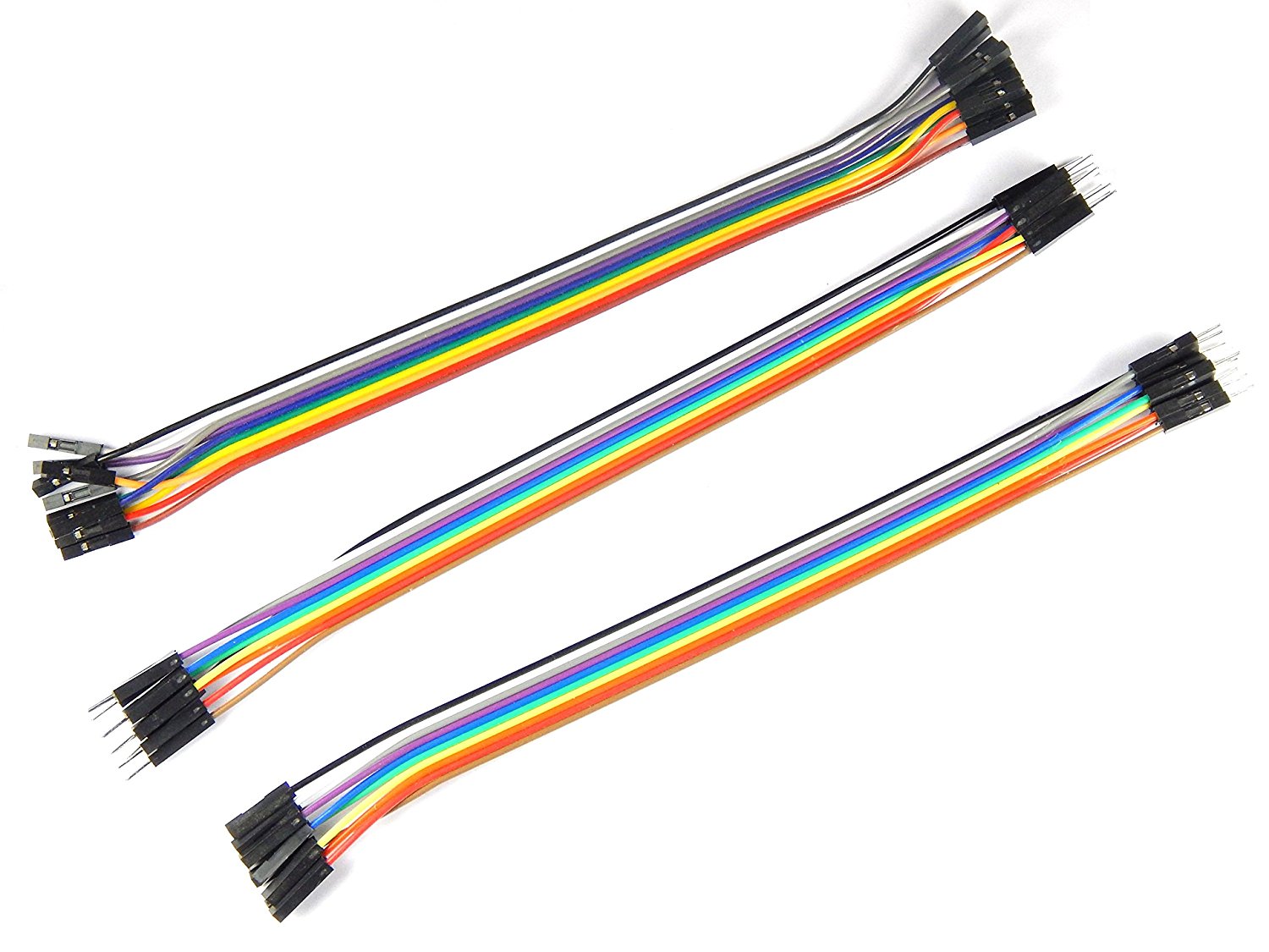
- Jumper Wires
- Arduino IDE
Installing NodeMCU Board Package
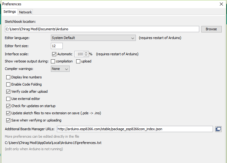
- Open up Arduino IDE. Go to Files-> Preferences. Enter http://arduino.esp8266.com/stable/package_esp8266... into Additional Board Manager URLs field
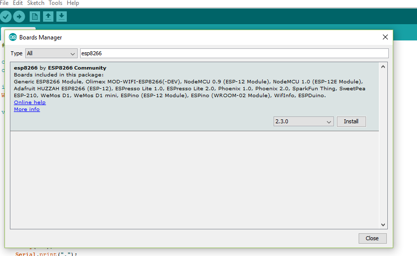
- Now go to Tools->Boards->Board Manager, and search for ESP8266 and install the package.
Pin Connections
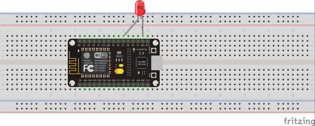
- D7 of NodeMCU to LED's +ve.
- G of NodeMCU to LED's -ve.
Source Code
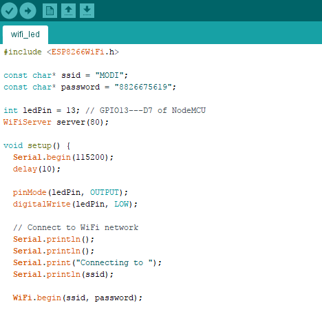
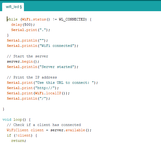
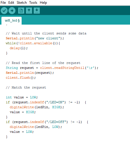
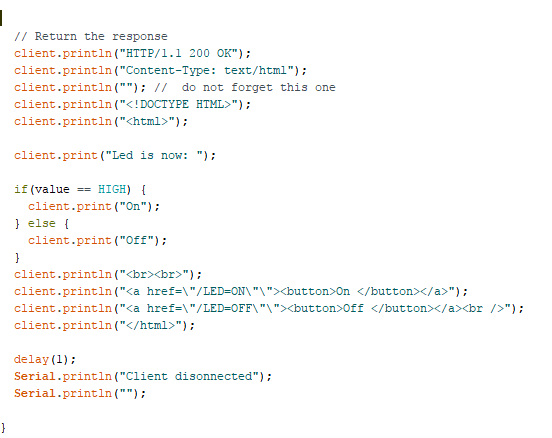
In code
change ssid to your ssid name
and Password to your SSID's password
const char* ssid = "MODI";//your ssid
const char* password = "8826675619";//Your Password
Downloads
Uploading the Code
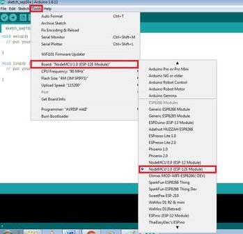
When u have successfully built your connection on the breadboard and write coding, you have to upload the coding into the NodeMCU by using a micro USB.
Now, go to Tools > Board > ESP8266 Modules and you can see many options for ESP8266. Select "NodeMCU 1.0 (ESP-12E Module). Next, select your port. If you cant recognize your port, go to the Control Panel > System > Device Manager > Port and update your USB driver.
Now upload the code to the board.
Controlling the LED
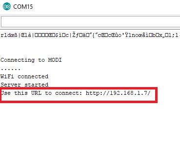
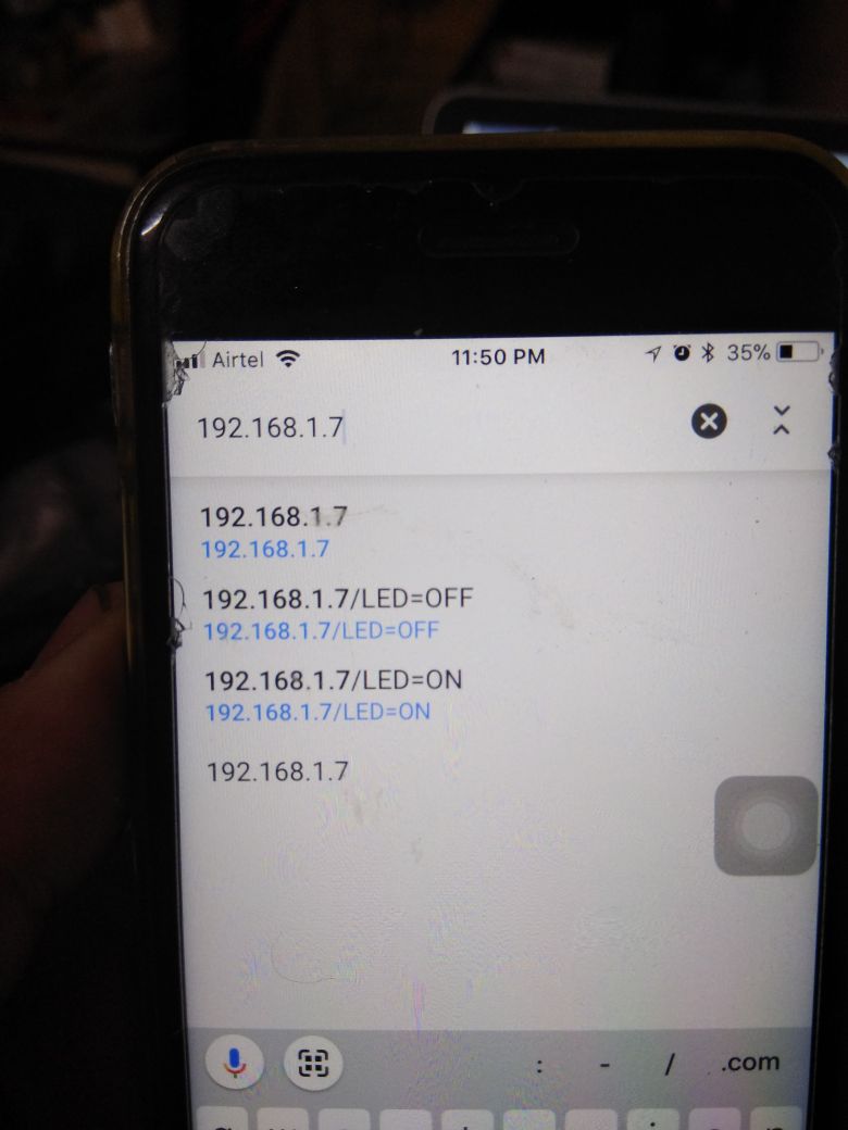
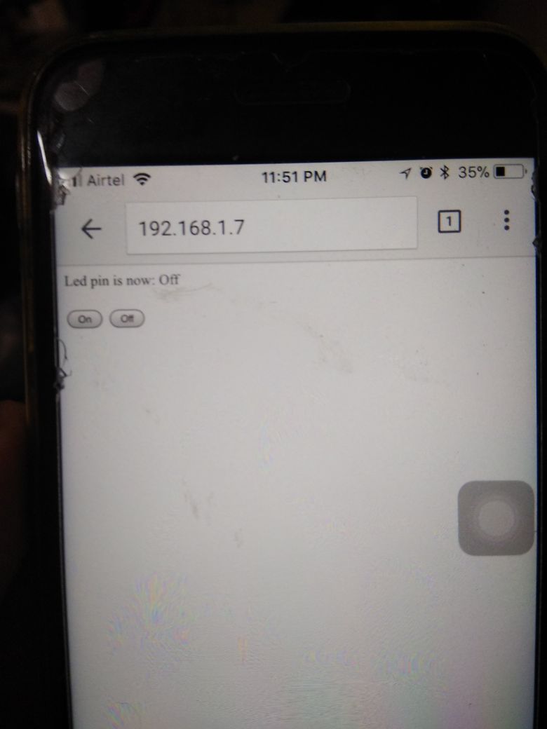.jpeg)
- Now open up your Serial Monitor, and not down the URL.
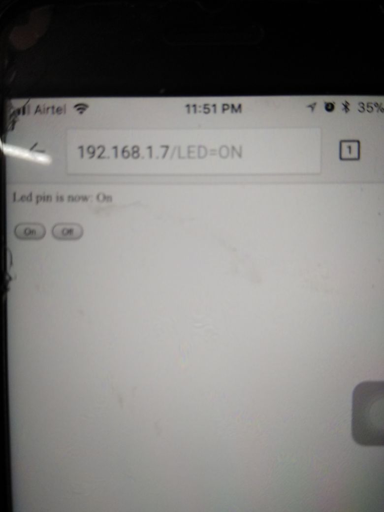
- Now put the URL in your phone's browser.
- A page will open having two buttons ON and OFF.
- If everything is correct when you press ON the LED will light up and when you press OFF the LED will turn off.