Intermediate Turning
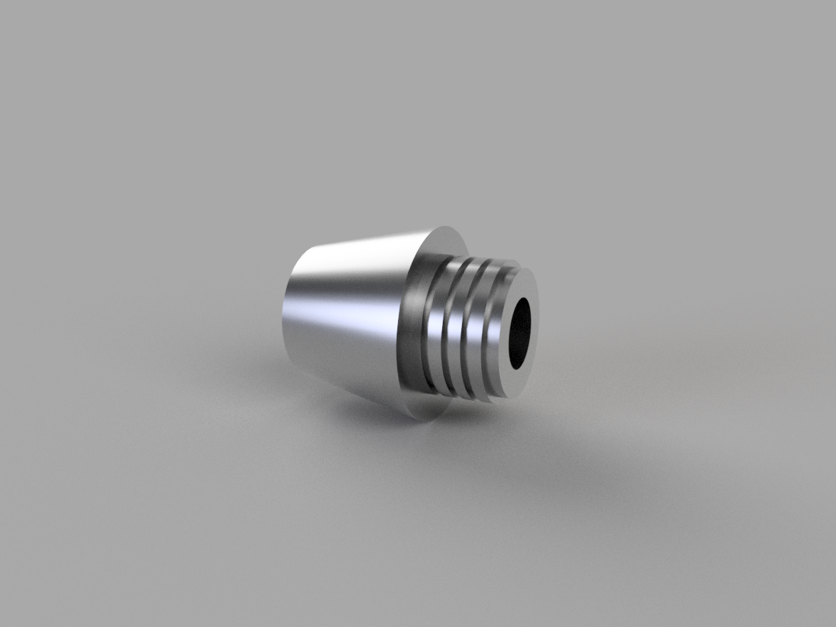
In this lesson, we will program another lathe part using FeatureCAM. This time, instead of starting from a drawing, we will import a solid model into FeatureCAM and extract features from it. Although some processes, such as feature creation, will necessarily be different, the overall workflow will remain the same.
In this lesson, you will learn how to successfully import CAD models into a FeatureCAM document, how to extract curves from geometry, how to transfer a part between spindles and how to change the machining configurations. You will also continue to grow confident using the workflow in FeatureCAM as a guide to program your parts.
Import, Stock, Machining Prep
The first step in our workflow is opening a new document. This is where we define what type of machining we will be doing, the units of measurement and the machining configurations.
- Open a new document
- Turn/Mill Setup
- Inch
- None
- My Configuration
With a blank milling document open, we can now import our solid model to program features from.
- Import Turning Part 2.x_t
Once the part is imported, we are met with the Import Wizard, and reach the next step in our Workflow – Stock.
The Import Wizard will help us setup our part, covering our stock step, as well as some of our machining prep.
- Align the Z direction by using ‘Align z with center of a revolved surface’
- Reverse Z if necessary
Step through the next few windows in the import wizard to define the piece of material we will be machining this part from
- Round stock shape
- OD: 2”
- Length: 2”
- Length Offset: 0.03”
- ID: 0
- Place the Setup at face of the stock and offset the Z so that the setup is even with the part face, as opposed to the stock face.

Now that we have completely worked through the import wizard, we are just a few short steps away from creating features.
- Select the ‘basic’ tool crib
- Select the Turn Post 2 post-processor
With our part imported, stock setup, and machining details accounted for, we are ready to start programming.
Create Features
In the last exercise, we created features from dimensions and curves. In this exercise, we will be using the solid model to help us define our features.
First, lets create a turn feature. This still needs to be created from a curve, but this time we can draw the curve directly from the geometry.
- Create a curve from Revolved Boundary
 with
convert to geometry on
- Use pick pieces
 to create a curve along the
outer profile of the part

- First, let’s create Face Feature
- Thickness 0.03”
- Inner Diameter 0
- Outer Diameter 2”
- Press Next
- Position at Z = 0
- Press Finish
- Create a Turn Feature from curve
- Use curve 1
- Press Finish
- Use pick pieces to create a curve along the groove profiles

- Create a Groove Feature from curves
- Use curve 2
- Press Finish
- Repeat this process for the remaining 3 grooves
- Finally, create a Part Handling Feature
- Select Slug Transfer
- Grab Distance 0 .6”
- Feed Distance 0.7”
- Press Next
- Finish
We have now finished programming the first side of our part and have transferred it to the second spindle. To start creating the next set of features, first we need to create a new setup.
- Create a new setup for the sub-spindle
- Open the Setups dialog box
- Select New
- Leave the name of the setup as default
- Press Next
- Align to Stock Face
- Choose the opposite side
- Press Next
- Offset Z by -0.03” so that the setup is aligned to the part rather than the stock
- Press Next
- Select Sub Spindle
- Press Finish
We can use the same geometry we extracted from the revolved boundary to create curves for this set of features.
- Create a Turn Feature from curve
- Use curve 1
- Press Finish
- Use pick pieces to create a curve along the Bore diameter

- Create a Bore Feature from curves
- Use curve 5
- Press Finish
- Open the Strategy tab
- Add a Pre-Drill with Diameter 0.5” and depth 1.94”
- Apply and then OK
- Finally, create a Face Feature from dimensions
- Thickness 0.03"
- Inner Diameter 0
- Outer Diameter 2”
- Press Next
- Position at Z = 0
- Press Finish
When you are done, your features should look similar to the features shown below.

At this point, we have programmed all the features necessary to machine this model accurately, and are ready to simulate our results and make any necessary revisions.
Simulate, Revise

Now, let's simulate the Features we just created, make any necessary changes, and simulate our final code.
- Run a Centerline Simulation
- Run a 3D Simulation
We are getting a gouge during the bore feature again. Let’s change the orientation of the tool we created in the last lesson so that we can use it on this bore feature too.
- Open the Tool Manager
- Change the Tool Group to ‘Lathe – Boring’
- Select the ¼” Bore Bar and press New Tool
- Change the name to EN ¼” Bore Bar
- Open the Orientation tab
- Select EN
- Press OK and then OK again
- Open the bore 1 properties window
- Select the Rough operation
- Check the box next to EN ¼” Bore Bar
- Apply and then OK
- Run a 3D Simulation
We can see that there is a thin piece of material left after the first turn feature. The turn features will also collide with the clamps holding our part when this program is run on our machine. We could change the curves guiding each feature, but let’s look at another option which we which is to limit the features with a boundary.
- Open the turn1 properties window
- Select the Rough operation
- Open the Turning tab
- Change Boundary (spindle side) to -0.8” then press Set
- Apply and then OK
- Open the turn2 properties window
- Select the Rough operation
- Open the Turning tab
- Change Boundary (spindle side) to -1.3” then press Set
- Apply and then OK
- Run a Centerline Simulation
At the moment, our turn 1 feature drops a small way into the grooves as it passes over them. This is unnecessary as we have separate features to machine the grooves and we can save machining time by stopping this from happening.
- Open the turn1 properties window
- Select the Rough operation
- Open the Turning tab
- Change the dropdown menu from ‘Adjust to tool geometry’ to ‘Remove all undercuts’
- Uncheck the ‘Auto Round Undercuts’ box
- Apply
- Do the same for the Finish operation
Let’s now take a look at another simulation type, machine simulation. This option, which is only available when there is a machine design file contained in our post folder, lets us see a 3D model of the machine as it machines our part. Unlike the other simulation types, it allows us to check whether there will be collisions between parts of the machine such as between tools and clamps.
- Run a Machine Simulation
We can now see that our main spindle clamp is holding the part in the wrong position.
- Click on My_Machine.md in the bottom right corner
- Z offset -1”
- OK
- Run a Machine Simulation
In the previous lesson, we made changes to the machining attributes to make changes to the default finish allowance and depth of cut across the whole document. It is also possible to save this as a machining configuration and load it when starting a new document
- Click on Machining Attributes in the Features and Machining
- Expand the Turn tree and open the Turn/Bore tab
- Change the rough depth of cut to 0.03”
- Change the z finish allowance to 0.002”
- OK
- Open Machining Configurations
- Highlight My Configuration
- Copy
NC Code

With our final simulation run, our NC Code has been generated and is ready to be sent to the machine.
- Select the Show NC icon
 to open our NC code in the Results window.
- Select the Save NC
 icon to save the displayed code.
- Save the NC code to your desired directory.
Note: This exercise is for educational purposes. The post-processor used in this exercise is a generic post-processor used for training that will likely not work for your machine. Do not attempt to run any code generated in this exercise.