Interlocked Ring Bracelet
by yogee1707 in Workshop > 3D Printing
1640 Views, 8 Favorites, 0 Comments
Interlocked Ring Bracelet
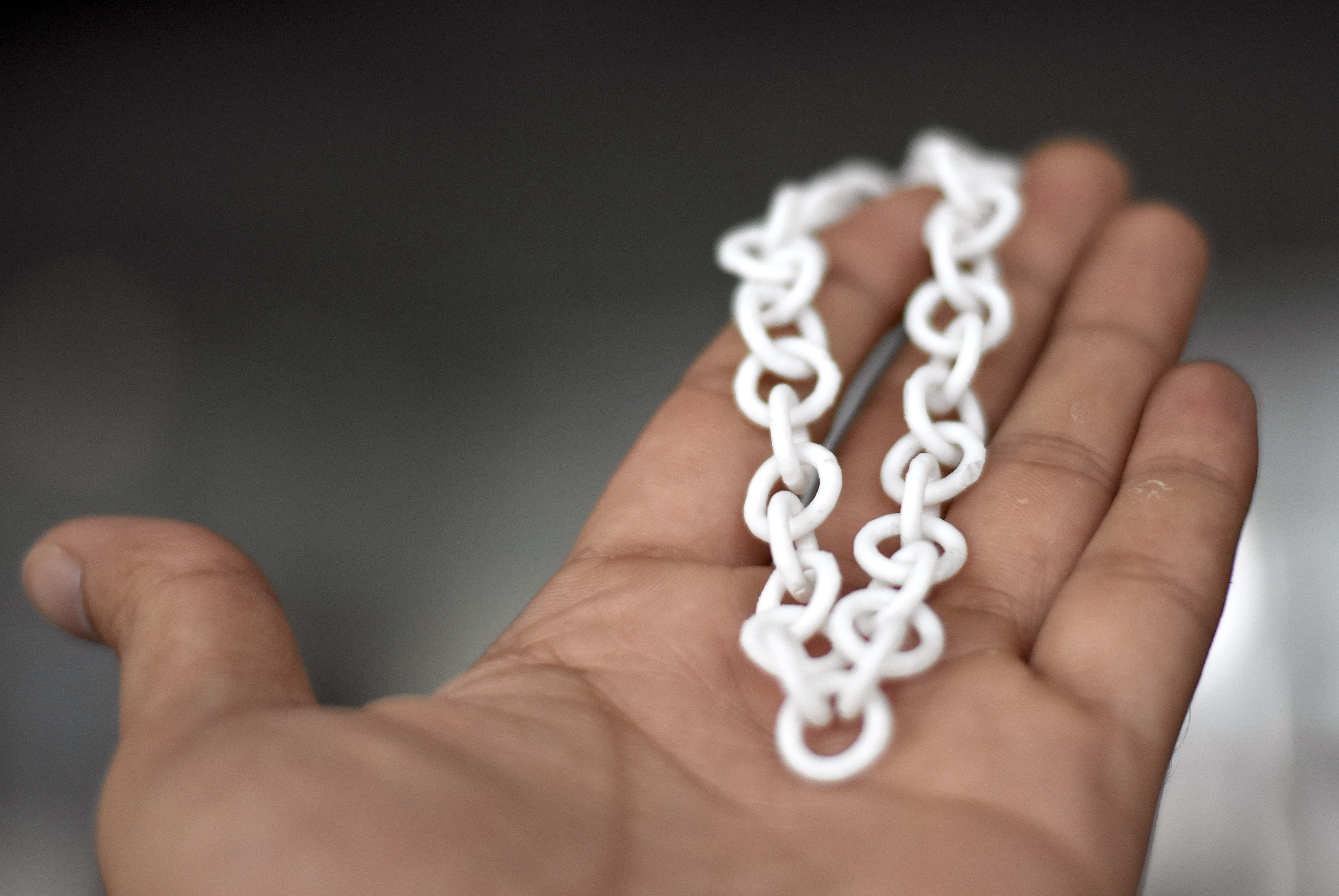
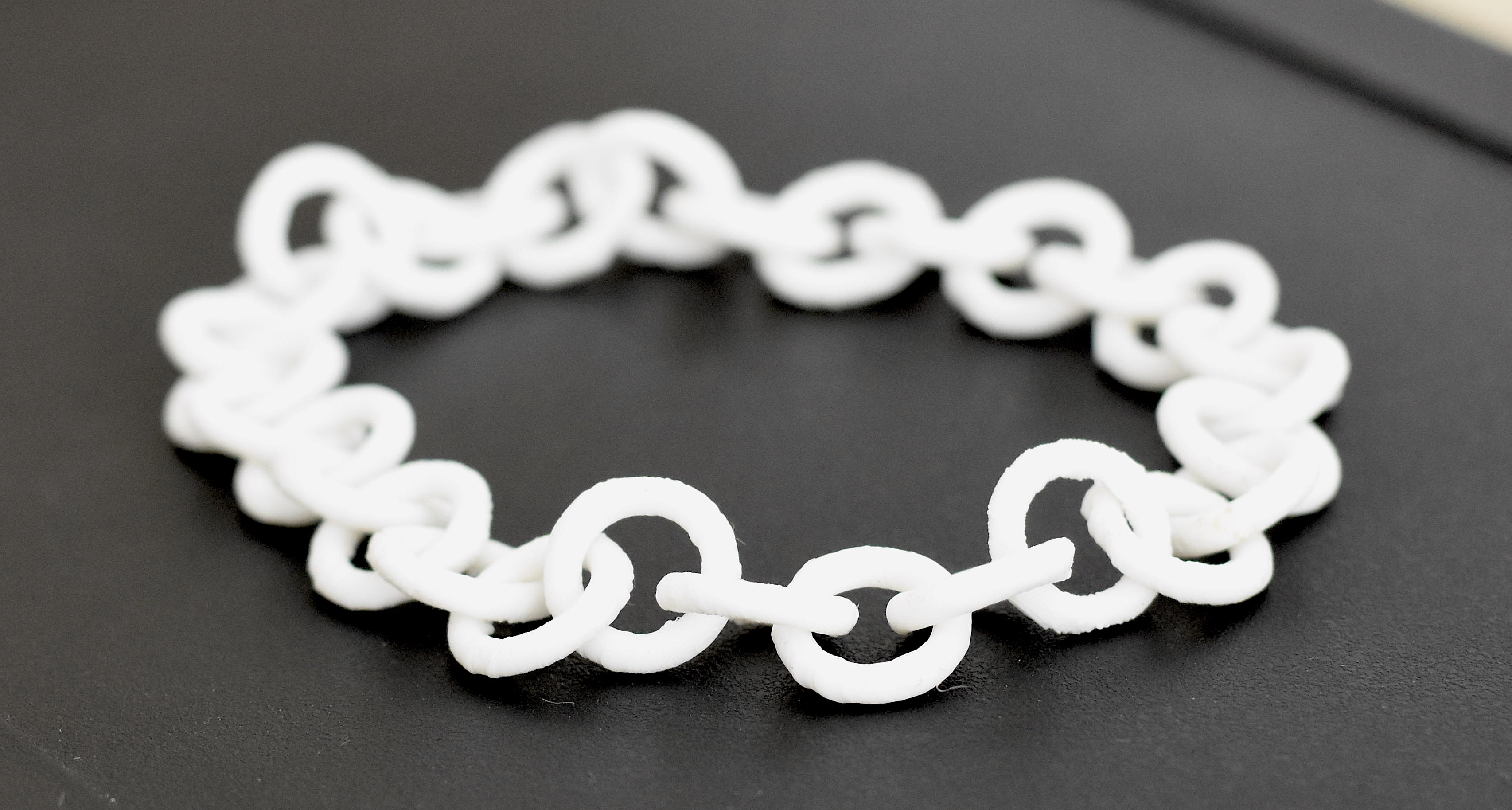
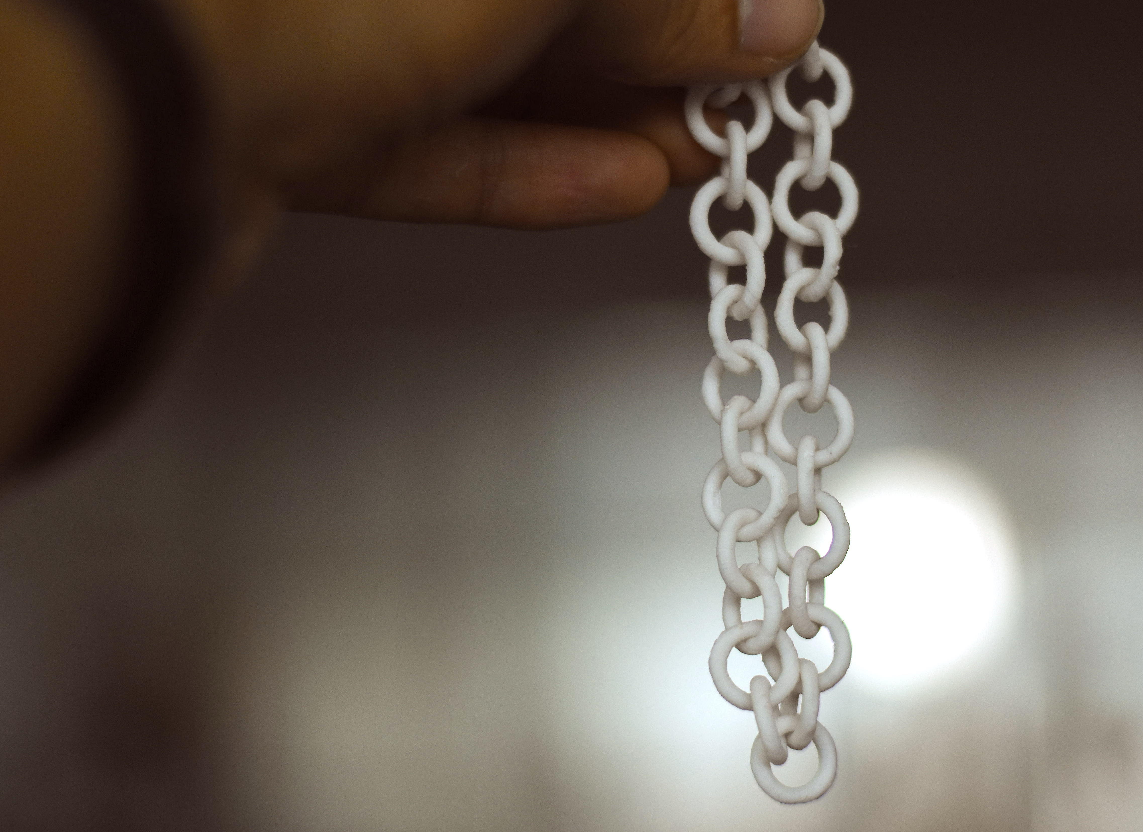
3D printing is peaking the interest of peoples from around the industries and domain, be it is the technology sector or the fashion, food, architecture, agriculture and so much more. This technology is disrupting the world around us, by enabling us to create incredibly complex structures which were not possible with the traditional manufacturing technologies. Today we can think of artifact in the morning, get off the bed get your hands on to that either by community shared models or if you have the guts, make it on your own; and magically in the afternoon with having a hot cup of soup you can see the machine realizing your thought. Pretty amazing, and thrilling. I'm sure this sounds like some sci-fi plot.
The technical name for the manufacturing process which 3D printer deploys is additive manufacturing. Let's break it down for easier understanding, additive + manufacturing, the first word itself suggest that we put something to make a lump, the addition is done in some systematic way to create the surfaces, profiles, and geometrical patterns. The word manufacturing still is a distant dream for 3D printing or additive manufacturing as the cost per piece is drastically high compared to the traditional mass production techniques.
So, today we will be diving into the top of creating an interlocked rings. The design could be extended into many possibilities and shapes to interlock. The basic shape we'll be using is the torus. Disclaimer, in this tutorial, I won't be explaining any of the complex equations, may or may not be involved in the process.
Let's pack your bag to be on adventure, following things are must,
- Fusion 360 - or an equivalent
- Flash forge Dreamer - equivalent
- Scrapping Tool
- Surface Cutter for removing supports
- Precise file set - Optional
- Flash Print - slicing and support generation utility for Flashforge printers
The above mention things are the essentials if you are suffering from some phobia feel free to carry your survival kit it may include,
- Kraft Glue Stick - if your prints are not adhering to build plate properly
- Paper Tape, Blue Printer Tape - to solve adhesion problem
- Printer specific accessories
So, I think you are ready to be on the voyage. Pull your pants up, jacket on and hit your favorite playlist and plug 'em in, your headphones, you voyager.
Introduction and Get Started With Fusion 360 or CAD
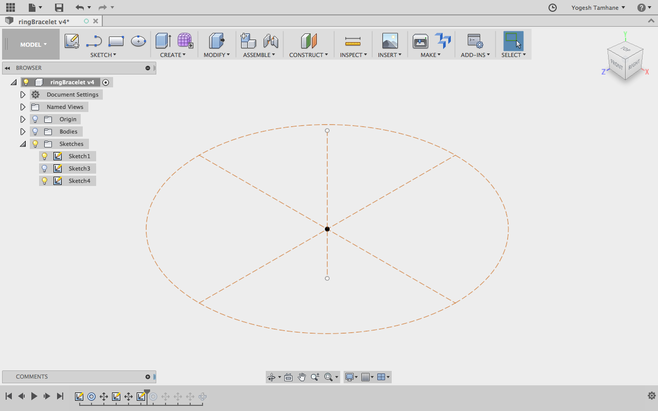
As website suggests "Fusion 360TM is the first 3D CAD, CAM, and CAE tool of its kind. It connects your entire product development process in a single cloud-based platform that works on both Mac and PC." The first thing first is that you have to get your hands on the Fusion 360 package to install it on your machine. I'm recommending this because it's a one stop shop for all the Maker needs and the free if you are a student or the educator. Take this amazing opportunity to grab your own free copy of it. Installation here is not a rocket science. The handy installer you can download from the website and run it to setup the software on your machine.
Here with the software, our aim is to create the design which can be. Processed to manufacture with the 3D printer. So, remember your 3D printer's minima and maxima in terms of printing specification. This is a super important aspect of the process because the if you disobey them then the printer will create a mess.
Step 1.1: Creating 3 Construction Lines
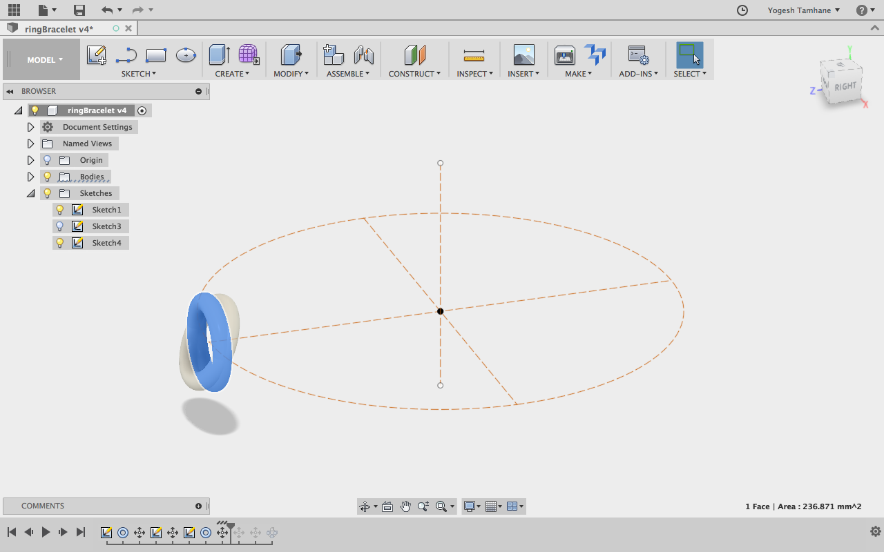
Once the software is set running, you have to jump in and create a torus. So, here I'll be creating a circle of a diameter equal or little greater than the size of your hand, here mine is 60 mm. approximately. To do so you have to select the sketch menu and enter into the sketch mode, now software is asking for the plan to draw the circle on. So, preferably use the top plane to draw, so you will save time in setting up your models in the printing utility. Once the circle is ready, then select the circle that you've drawn and hit "X" which will create the sketch into the guideline or construction line. This is the line which can be used as a reference and have no value when it comes to defining shape or contours. These construction lines are used to define the path in which the sketches or bodies should get aligned. Now, select the line tool to draw a line, again construction line, but this should be in the perpendicular to the plane in which we have drawn the circle previously and the line should be exactly at the center of the circle drawn, note here that the length of the line is trivial, it doesn't matter, but it should be easily identifiable and selectable in the woods or sketches and bodies. Note: Keep selecting the figures and after that pressing "X" on the keyboard to convert the sketches into construction lines and figures.
To summarise we have following construction geometry,
- Circle around the edge of which we will be putting up the toruses - C1
- Axis at the center of the above-mentioned circle - C2
Refer diagram.
Step 1.2: Create torus
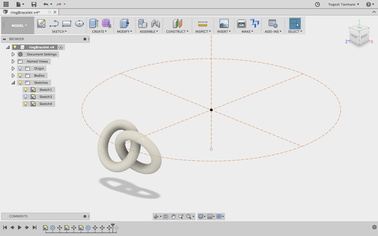
Now we have the construction geometry set. The torus of following dimensions, the diameter of the torus would be 10mm and the thickness or the diameter of the revolved pipe is 2.4 mm is to be created in the vertical place. As shown in the figure. Generally when you draw any of the figures in CAD always start with the origin, which will be easy for you to localize the object/ sketch drawn. Now, as we have drawn the torus at the origin, we have to move it on the circular construction line i.e. C1 as shown in the figure. To move the object you can right click on it and select the move command. Now according to the dimension of the circle, you have chosen. You have to move the torus, as we want to move the torus right on the circle's perimeter, i.e. you should move the circle from the center/origin equal to the radius of the circle. We will call this torus as T1.
Once the torus is placed on the perimeter of the circle C1. It's time to tilt the torus in the desired angle. For the dimension, I took i.e. 60mm of C1 I've tilted the torus at 25-degree. It may change depending upon the dimension of the torus, be careful with it.
As the one of the torus of the group is set, it's time to go for another one. Repeat the procedure for drawing and aligning the torus at C1's edge. After aligning the torus at the edge, move it laterally so that the torus T1 should be seen interlocked with T1. Once done. It's time to tilt it, you can repeat the procedure to tilt the torus in 25-degrees.
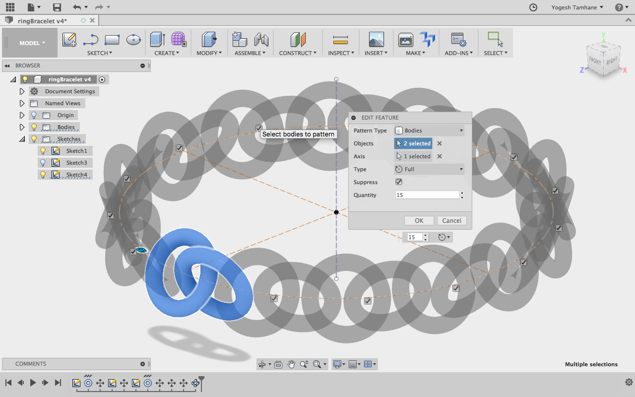
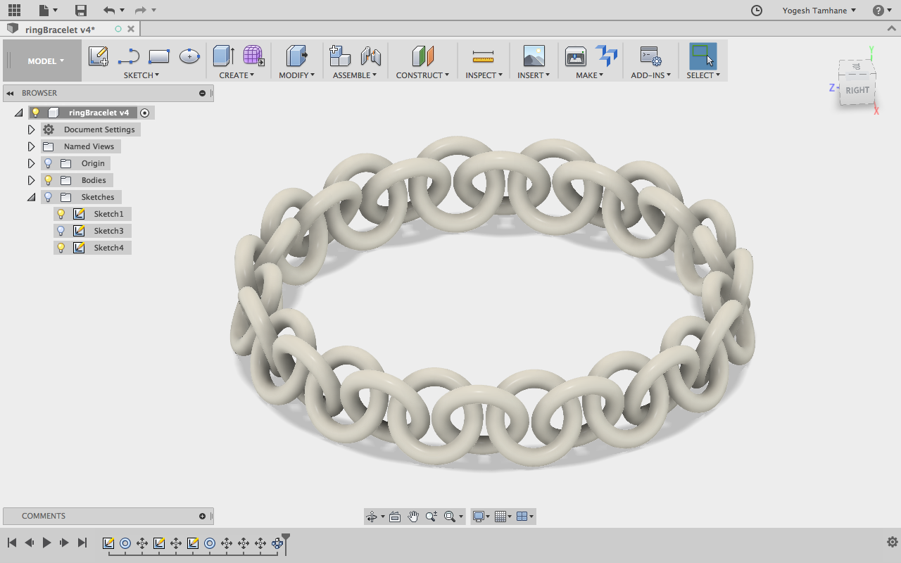
Now, what you have is a unit of chain i.e. two toruses interlocked. It's time to repeat the unit around the C2, to do so, access the Modify menu, and select the circular pattern option. This enables us to repeat the unit created. Now, there we have to define two things, 1st if what we want to repear and 2nd is around what we have to repeat, i.e. the axis. Now, select the both the toruses and in the dialog box click on the axis, and then select on the C1, the axis around which we will be repeating the unit. Now, you can see the ghost images of the bodies spread around the axis, now we can define the number of repeats, in my case 14 is plausible. Hit ohkay to freeze the design.
Step 1.3: Exporting the file in STL format for printing using Fusion 360
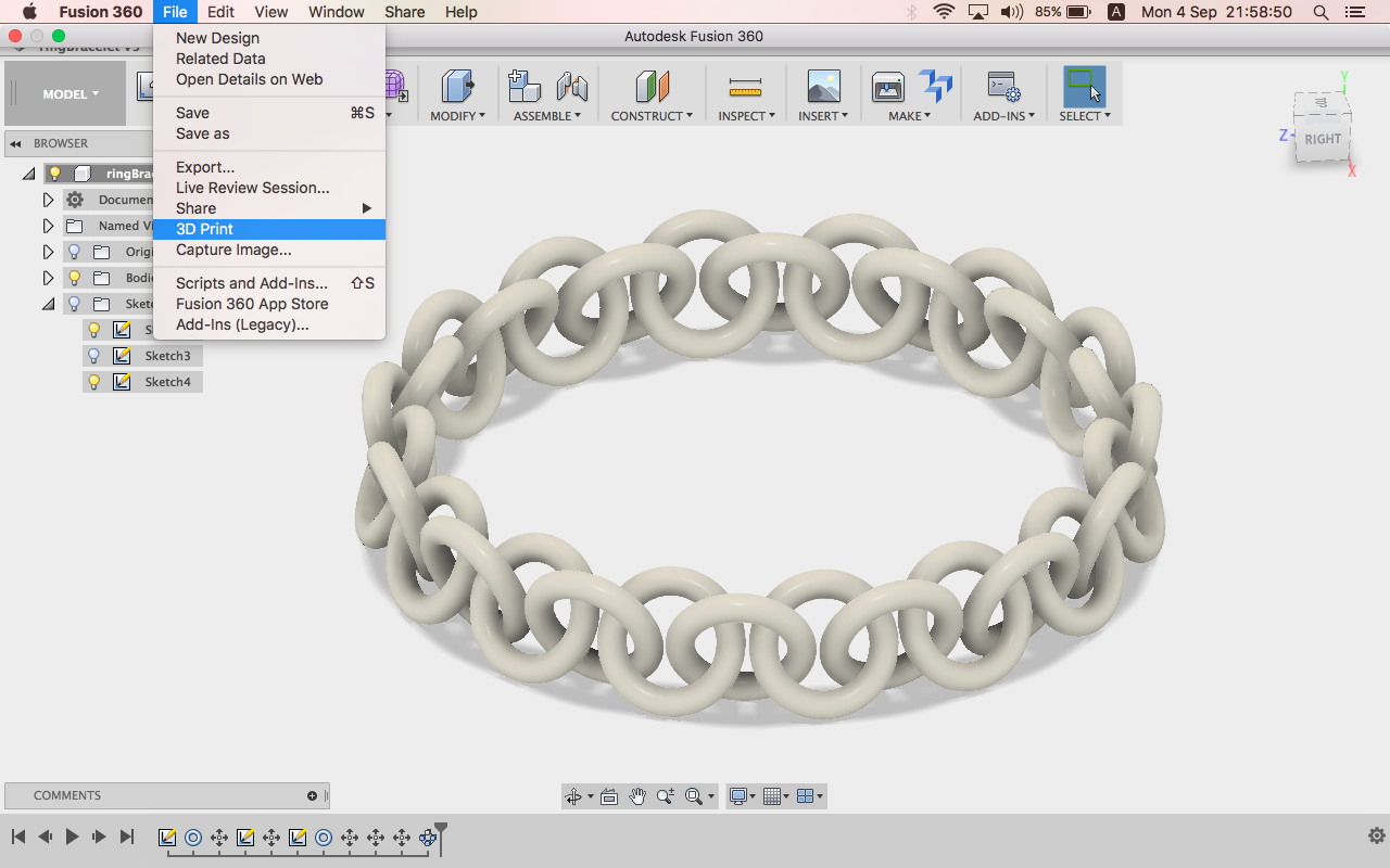
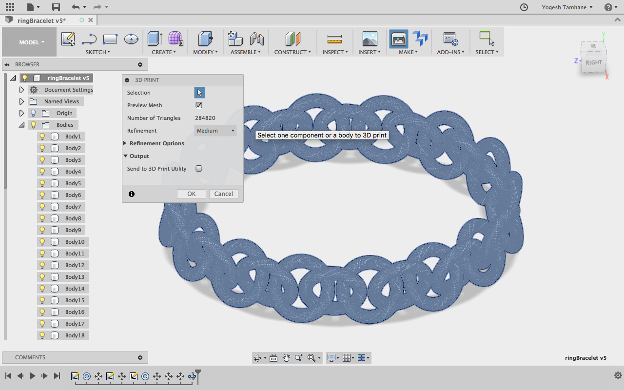
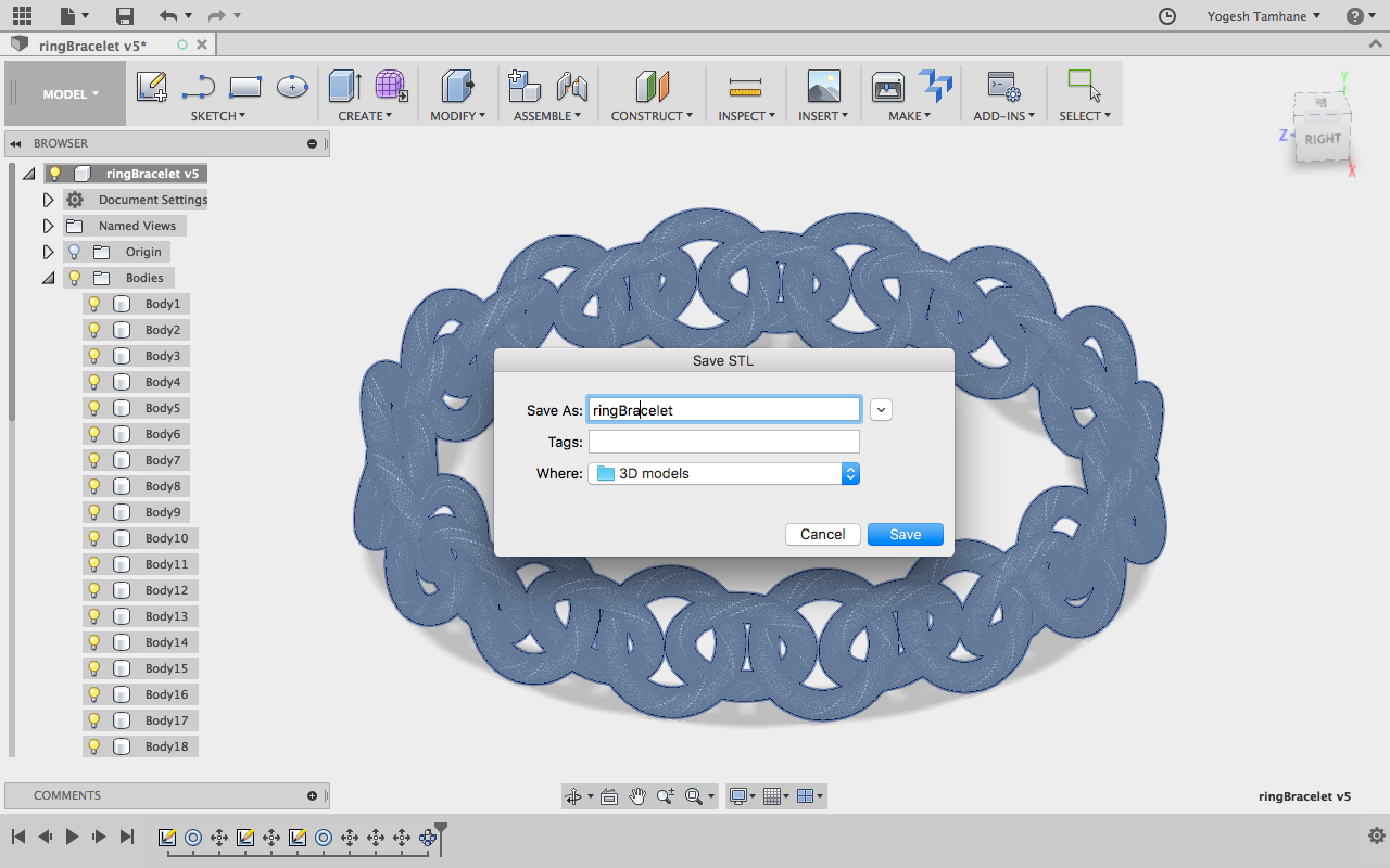
Almost all the 3D printer uses ".STL", formats. Now, to export using the Fusion 360 is little tricky. As we have multiple bodies, to do that, access the File menu and select 3D print. Once you do that, you have selected the bodies to be exported, select the main group called bodies to select every all the bodies present in your design. There is detailing option available to choose from, "Low, Medium, High", select Medium level, the file size will be moderate. In case of high obviously, the software will create superfine geometry with lots and lots of triangles. For our purpose and design, it's alright to choose Medium. Once you click "Okay" then it will ask you the location to save the STL file. Save it.
Time to move for printing.
3D Printing the Intelocked Ring
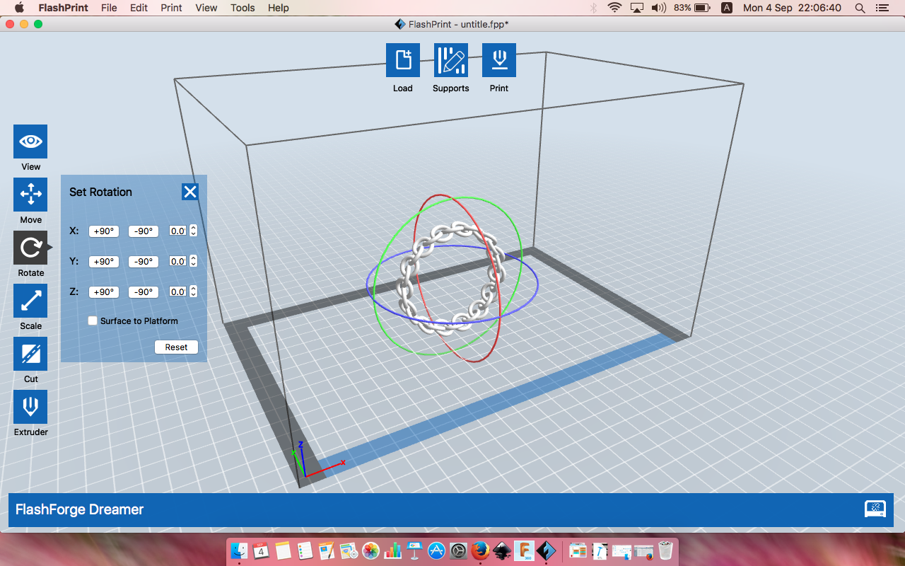
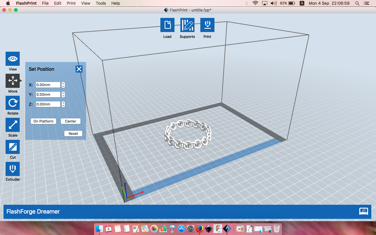
Depending upon which 3D printer you have the printing you might be having different utility to process the file to be printed. As I'll be using the Flashforge 3D printer, the utility used for the printing is known as Flashprint. I'm assuming you have your favorite utility up and running on your PC, let's start.
Step 2.1: Import the model .stl
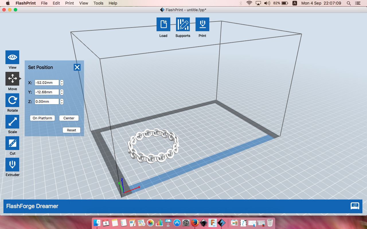
We have to import the object, we have desinged. Many utilities allow user to drag and drop the objects designed, go ahead and do that. As imported and model you have to arrange first. Arrange the object right on your bed as shown in the figure.
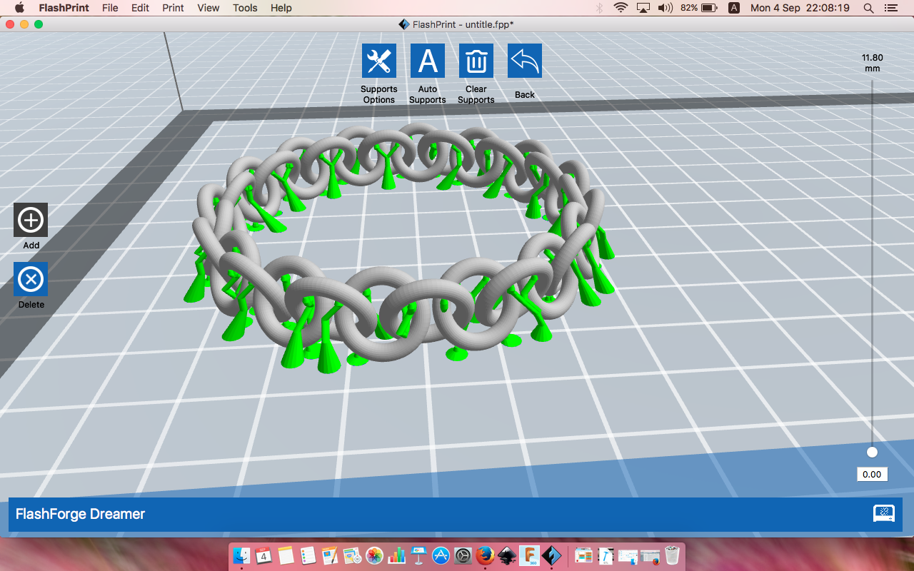
Look carefully at the object, look at the bottom surface, is it in the contact with base? yes, but at a point, as we have the circle as the base geometry, i.e. for every circular link the platform surface is like a tangent. Which is making it impossible to print without support, it's time to eliminate the worries. How?? simple, generate the supports. Many utilities generates the supprot on their automatically, based on the algorithm. So, go ahead and click on the auto support generation option, which is there in top edge of the window, the last option; help your self if you are not aware about your utility. Selecting ohkay will generate the supports, and will ask you to save the file. I prefer saving the file in the pendrive and connecting it to printer.
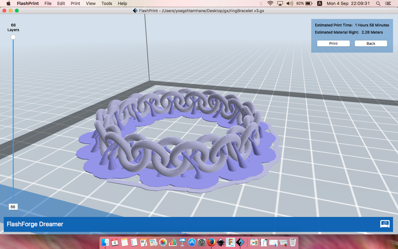
In the software it may or maynot suggest, but always remeber to add "Brim" where there is little surcface contact at the bottom of the object. Hit save and put it in to USB for printing.
Step 2.2: Setup the printer and hit print
While printing the files you have to ensure following things,
- Bed Leveling is proper - check your printer manual
- Suface if clean and adhesion friendly - Blue Tape or any adhesive surface.
- Engough spool is loaded
As it is not the printing tutorial, I'll be assuming everything is set. Go ahead connect USB and click print.