Interfacing With an LCD Display M4Inclusion
by HorizonLab in Circuits > Arduino
478 Views, 0 Favorites, 0 Comments
Interfacing With an LCD Display M4Inclusion

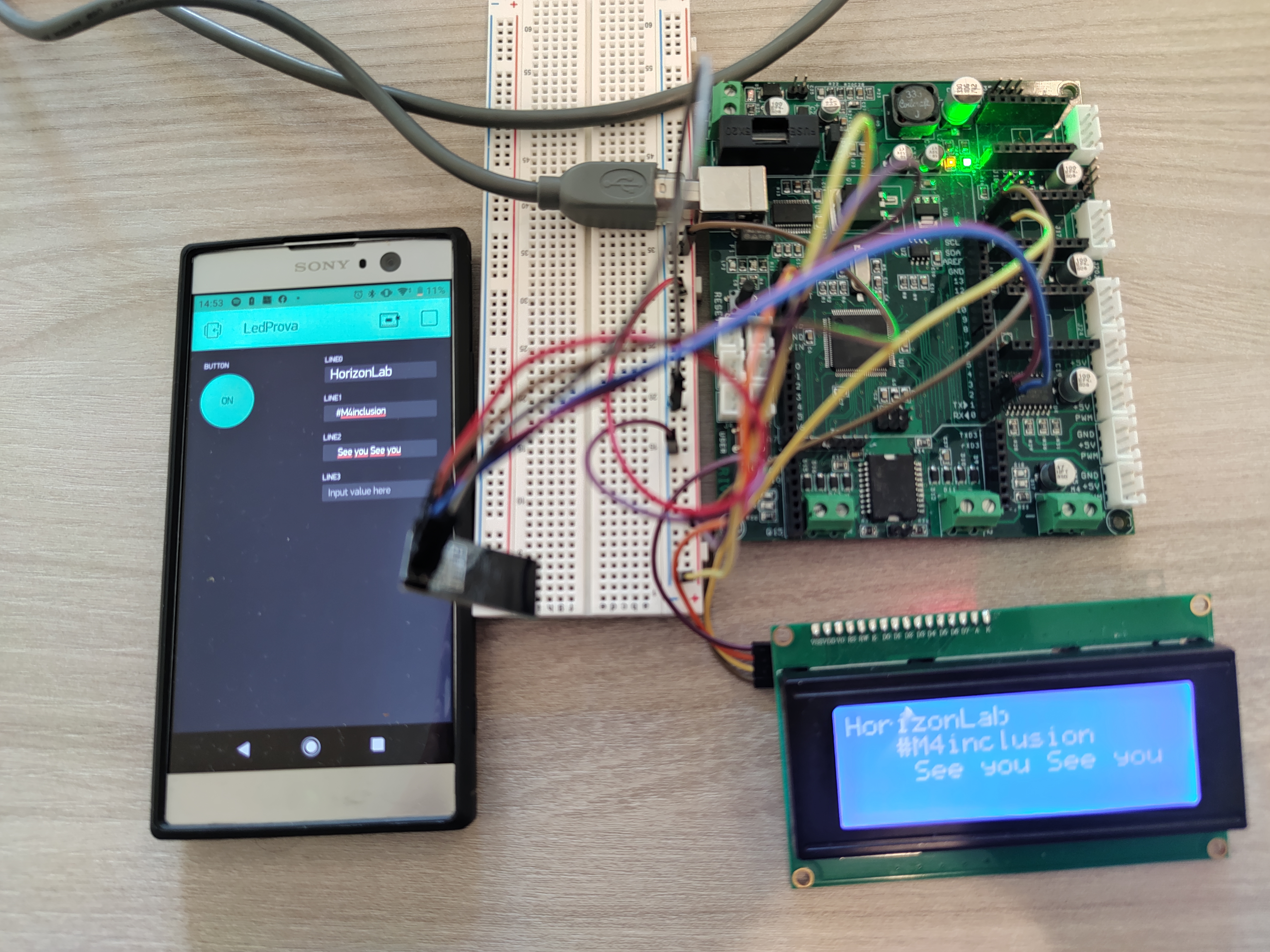
This tutorial will allow us to control an LCD display via Wi-Fi from our smartphone
If we do not have the drivermall we can use the arduino, but below the link for the development of the Drivemall.
The advantage of prefering the Drivemall over the classic Arduino board is that of reducing the complexity of the connections leading to a more tidy setup (in some cases). However, this is optional: all the results are still valid with the arduino board, a breadboard and enough dupont jumpers for connections.
The project aims to promote an informal form of education as a means to foster social inclusion of young people, informal education as can be found within makerspaces.
This tutorial reflects the views only of the authors, and the European Commission cannot be held responsible for any use which may be made of the information contained therein.
What We Need
- Arduino Mega-/ Drivermall
- ESP8266
- Display 20x4 I2C
- Resistor 1K
- Programmer CH340G
- LED
- BreadBoard
- Cables
- Smartphone
How to Configure Blynk and Arduino
.png)
Let's start downloading Blynk on the smartphone.
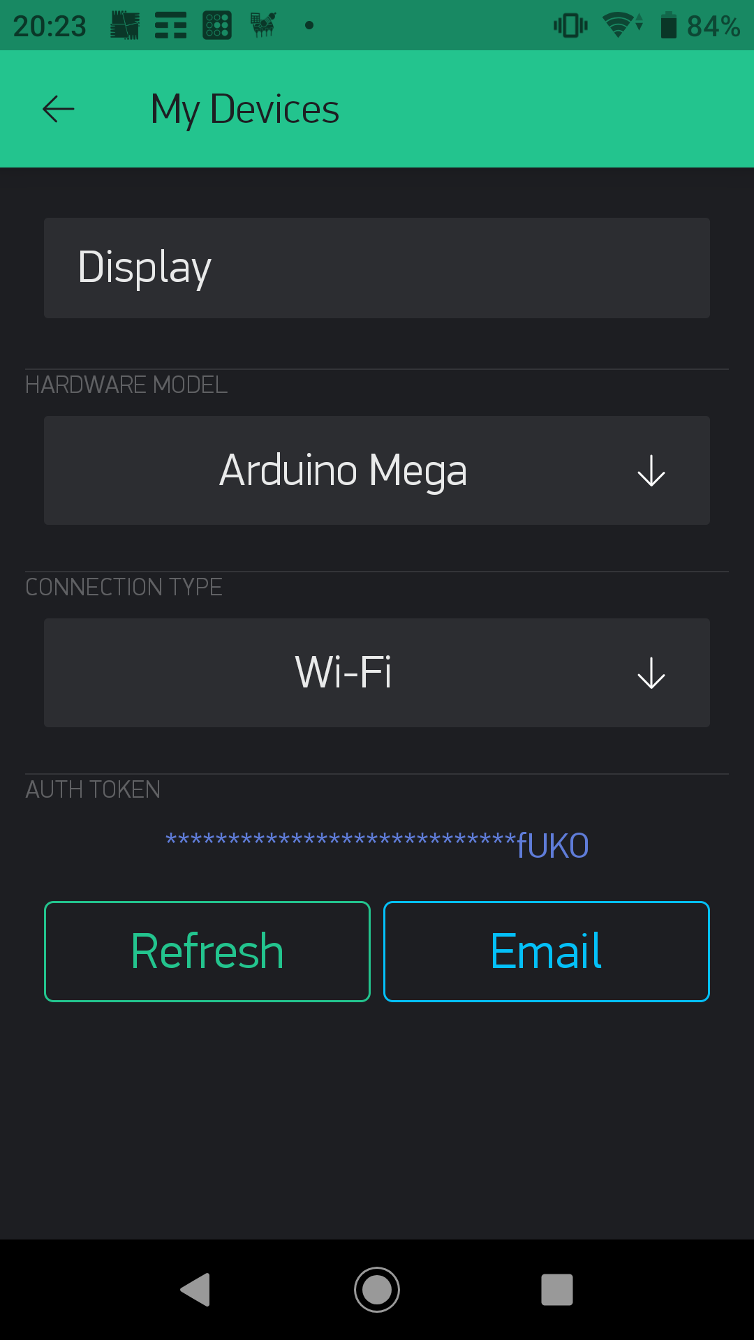
Create a new project selecting as hardware Arduino Mega and connection type WiFi (pictures 1). Once the project is created, you get a mail with the Blynk token for your project.
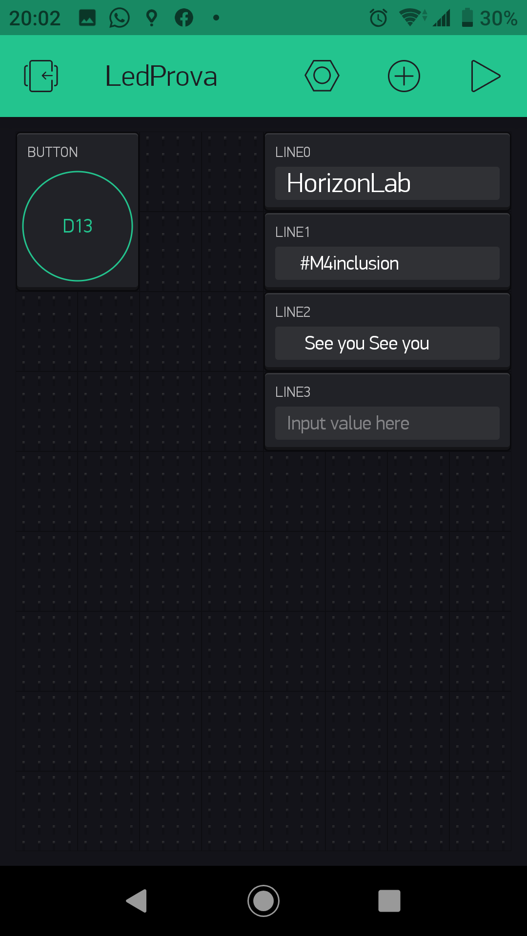
Let's now configure it to be able to control the display by adding:
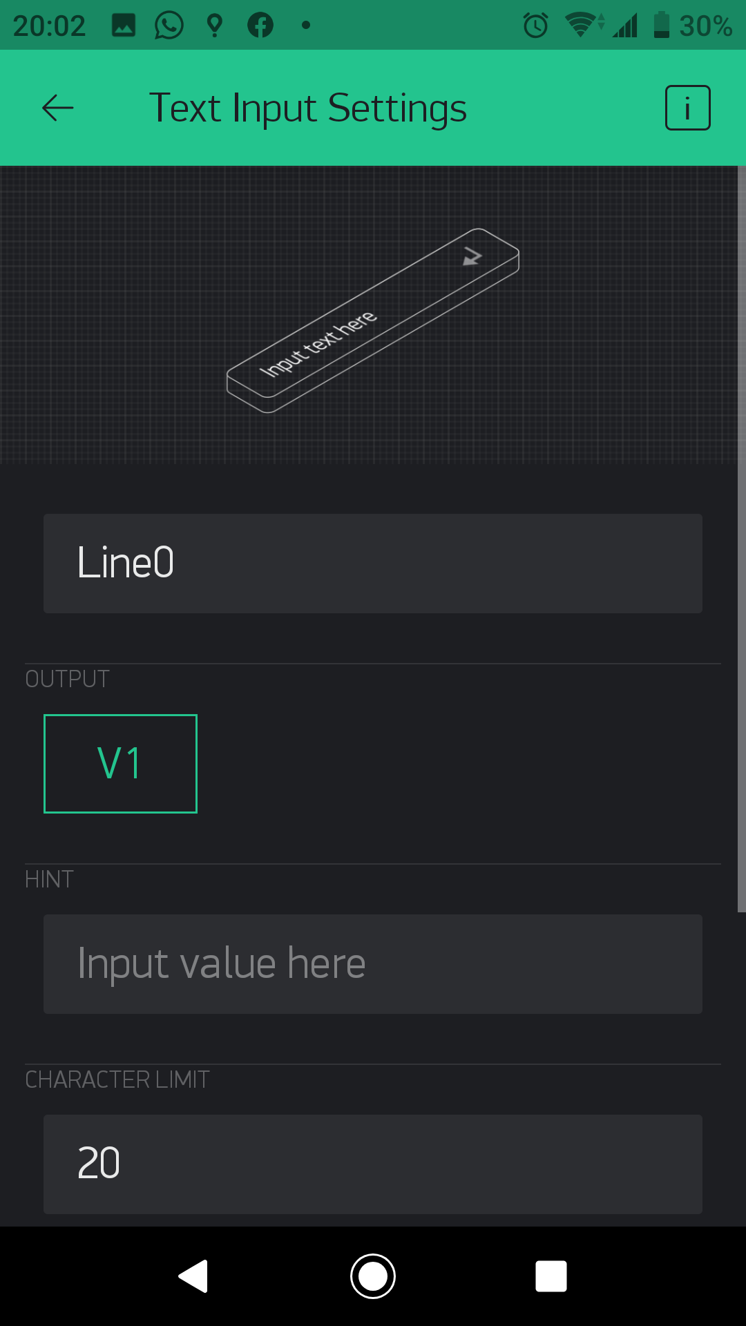
4 Text Input Settings with Output V1-V2-V3-V4
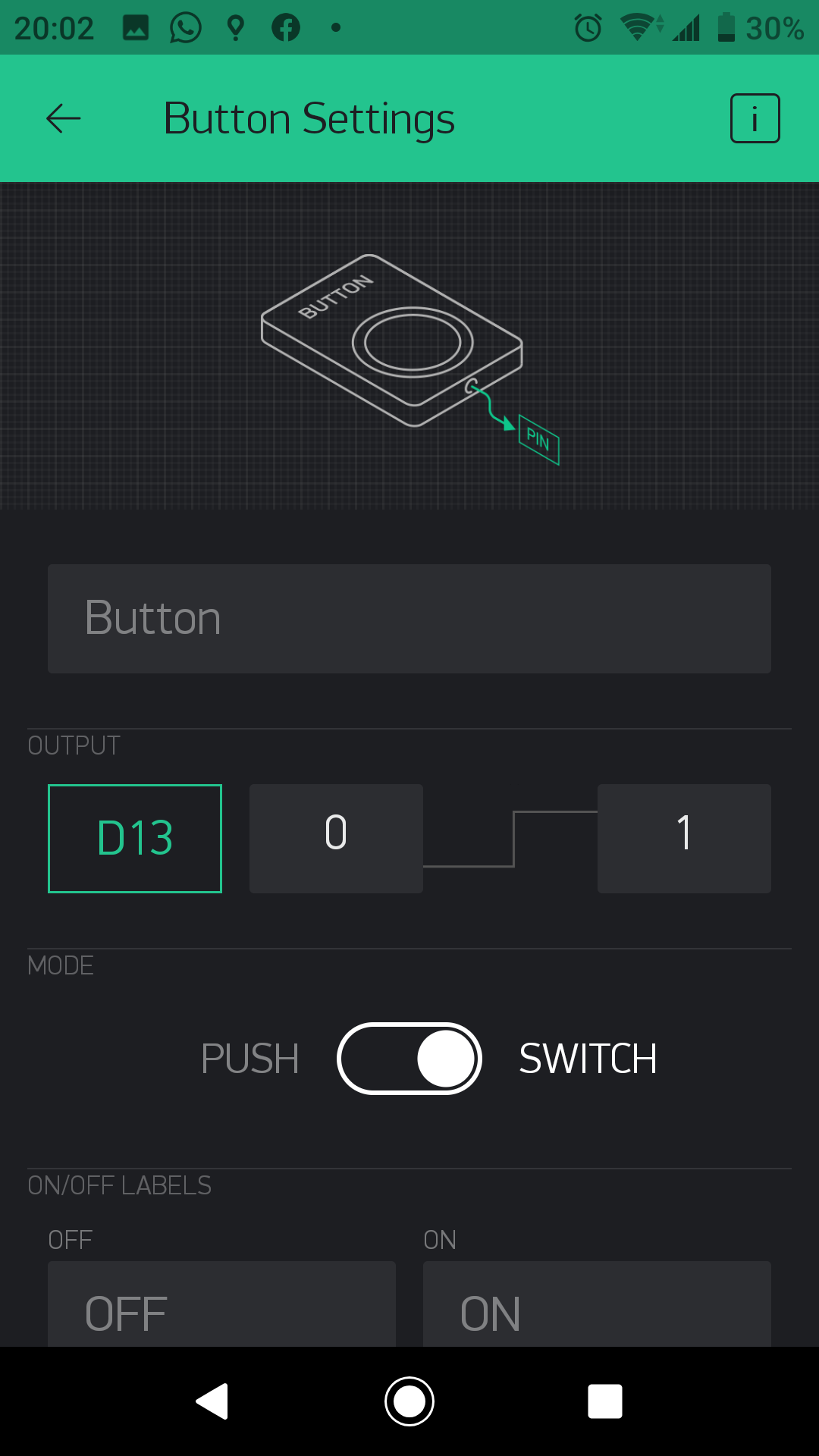
1 button connected to D13
FW for ESP8266
First Step ESP8266
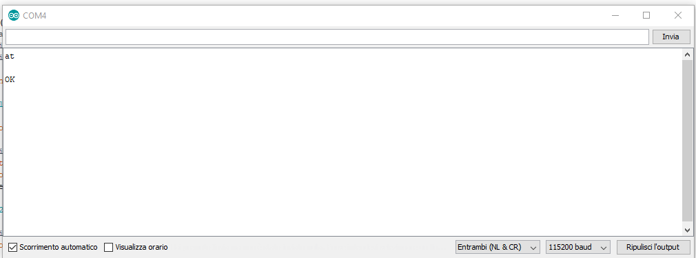
We check if the FW is present through the Arduino serial monitor (picture 1)
The default baud rate of the esp is set at 115200. To check the presence of the SW we use the AT command if it answers OK we can go ahead and set the baud rate to 9600 using the command
AT+UART_DEF=9600,8,1,0,0
If the fw is not present
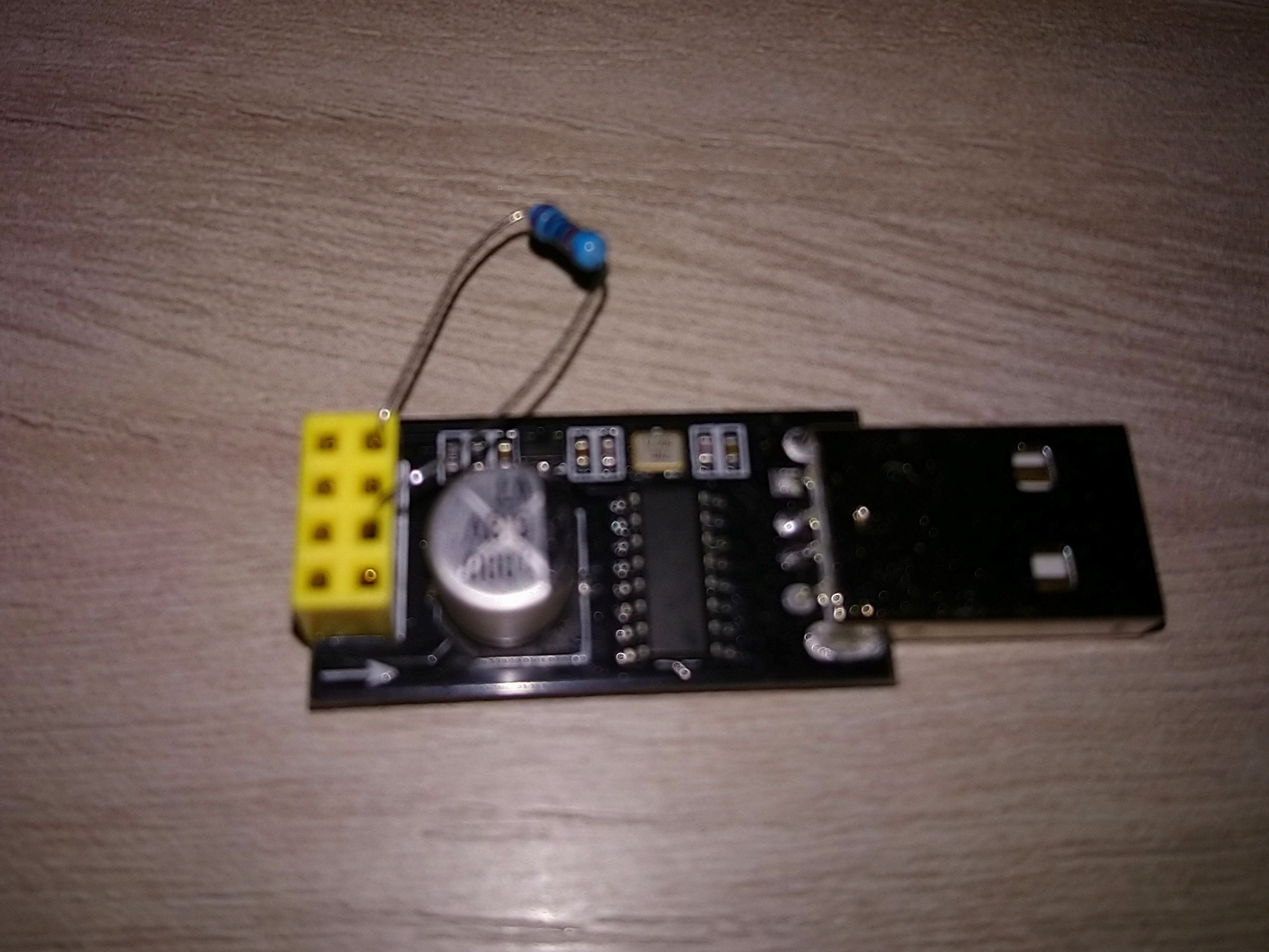
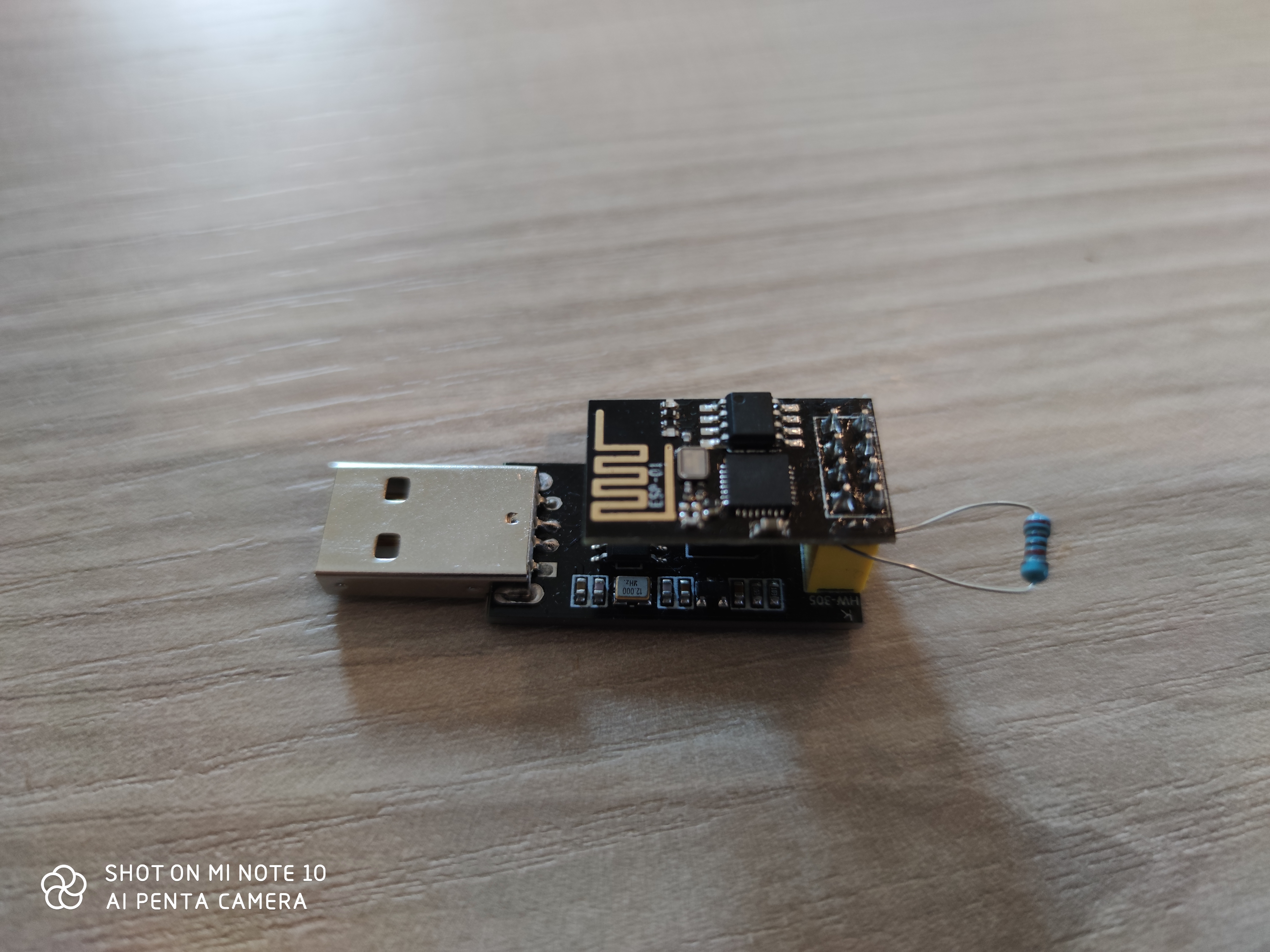
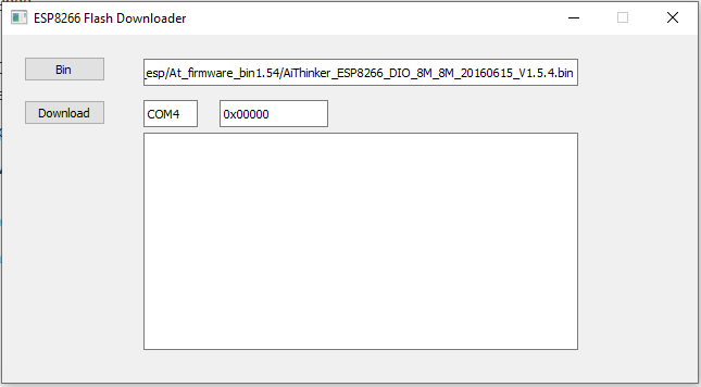
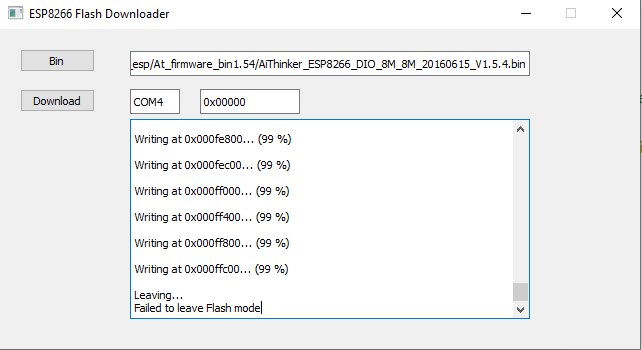
Load the firmware AiThinker_ESP8266_DIO_8M_8M_20160615_V1.5.4 through the programmer by connect the PIN GPIO0/FLASH to GND through a 1K ohm resistor and we use the esp8266_flasher program (picture 2 and 3)
Select the correct COM port and we load the FW arrived at 99% could give an error but it is normal (picture 4 and 5)
How to Assemble
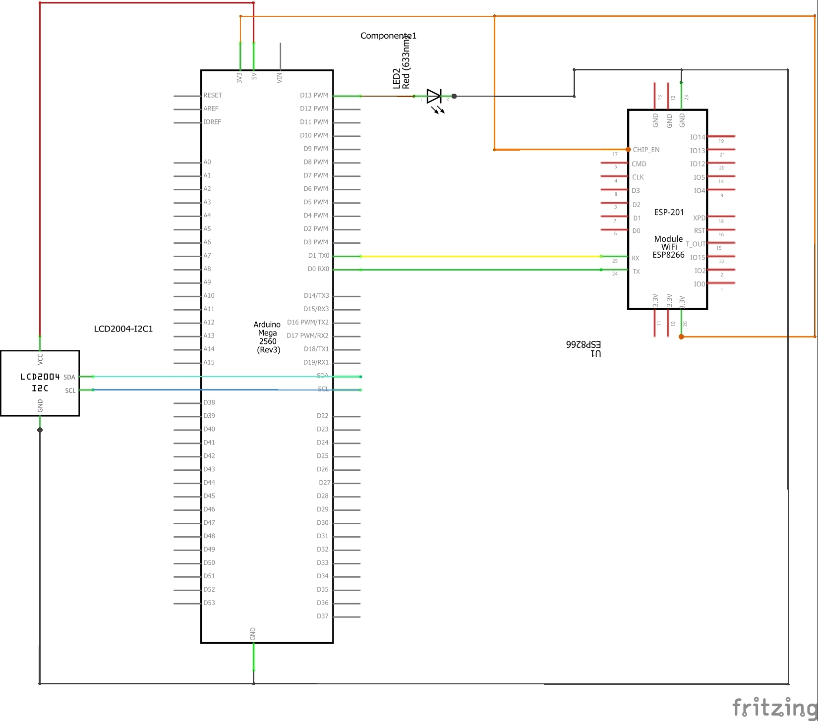
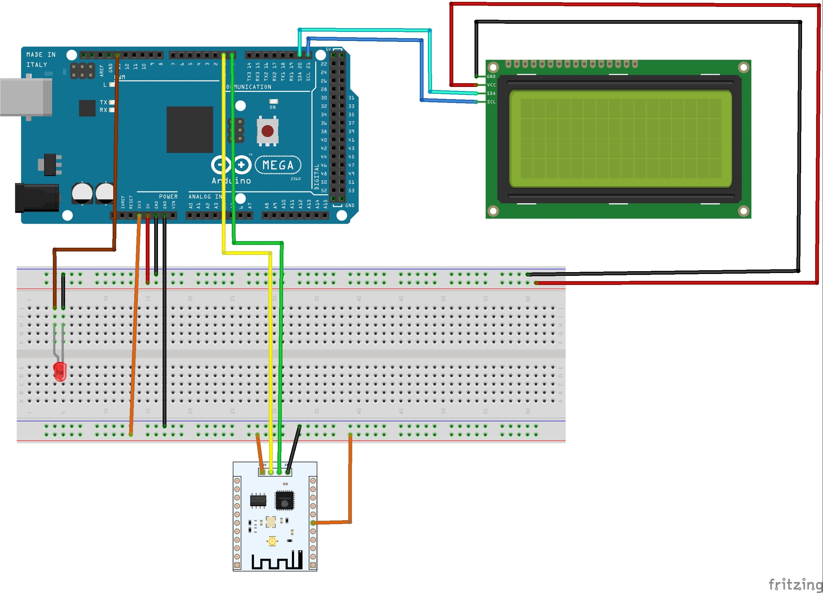
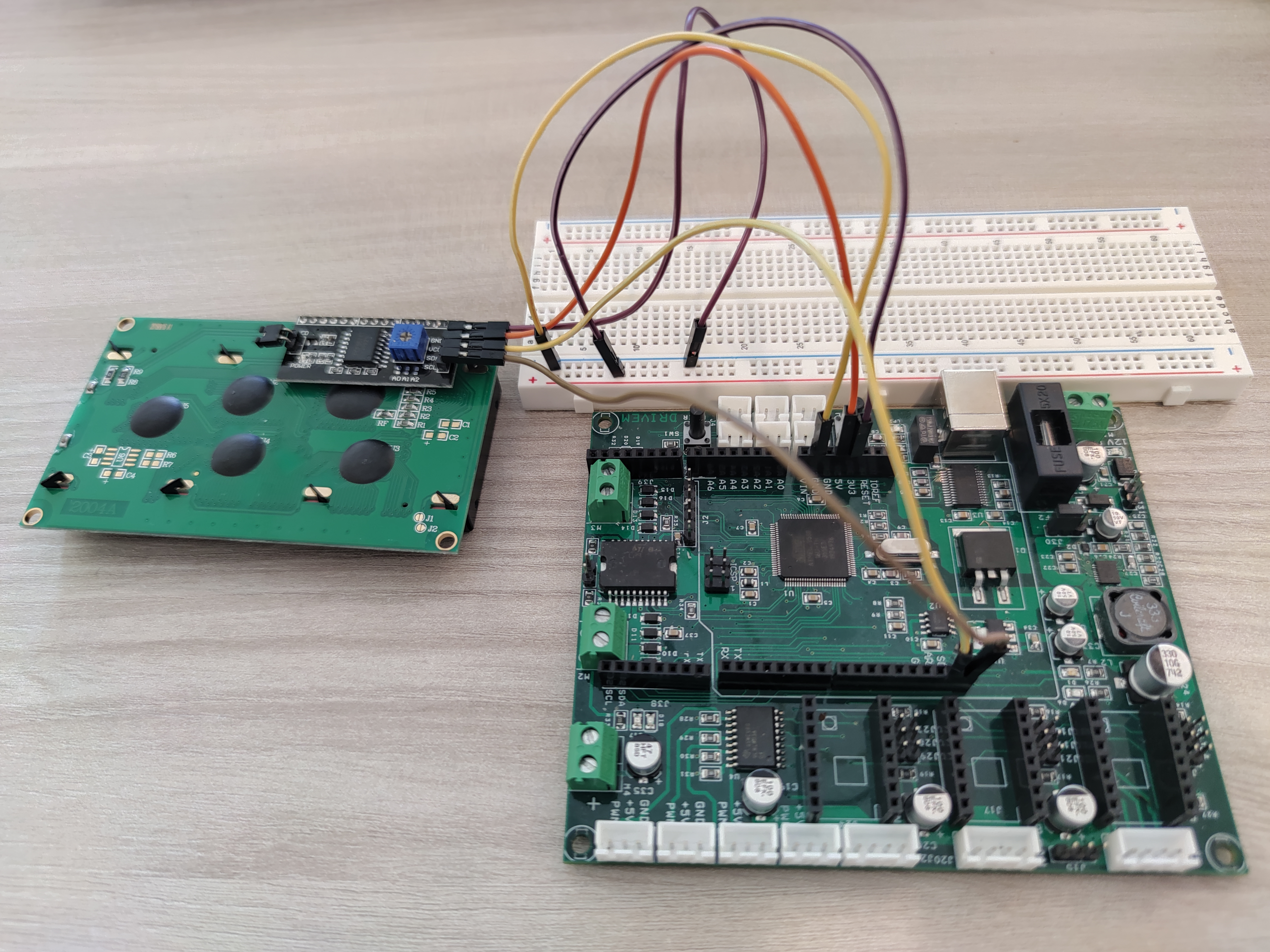
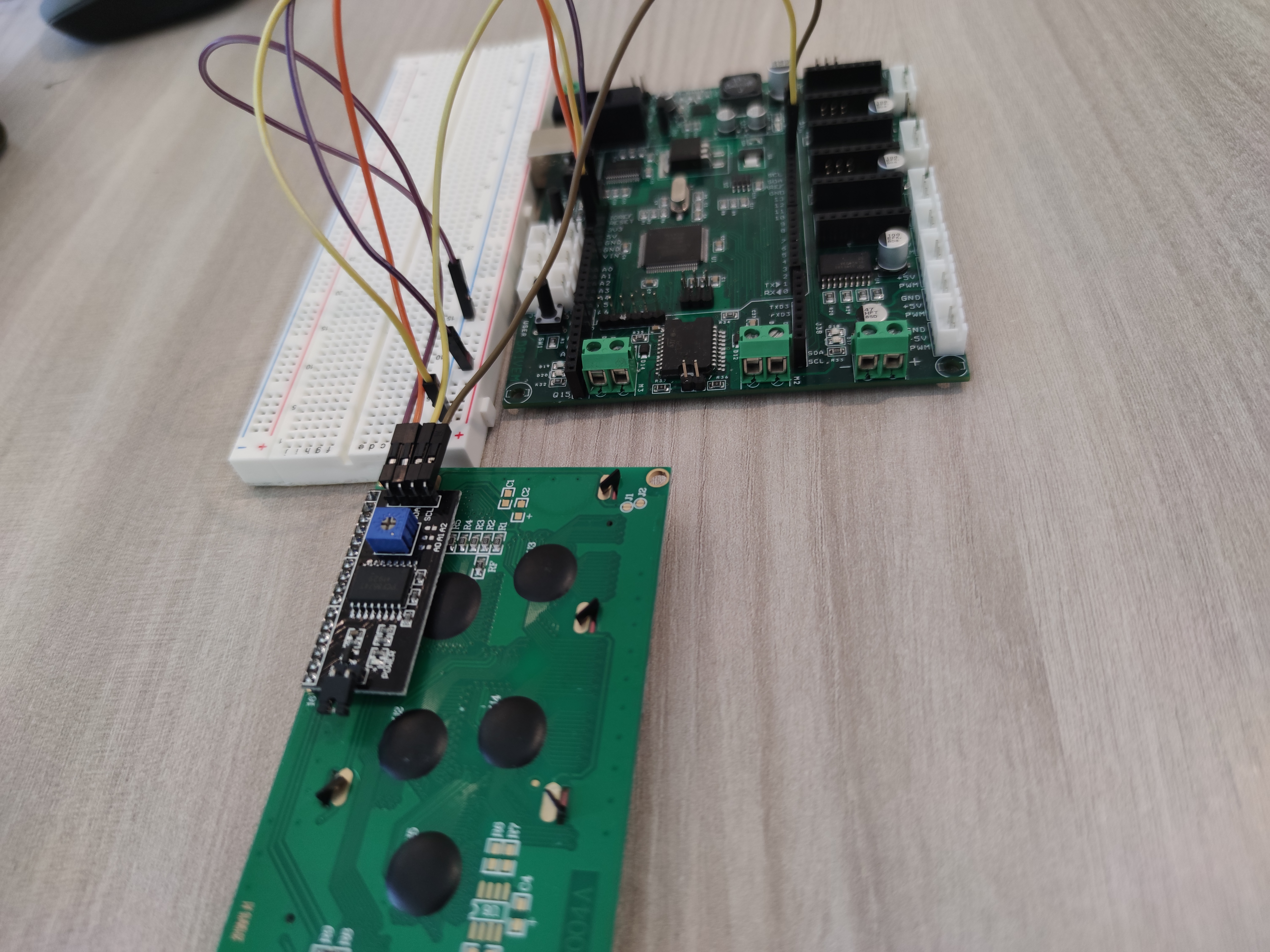
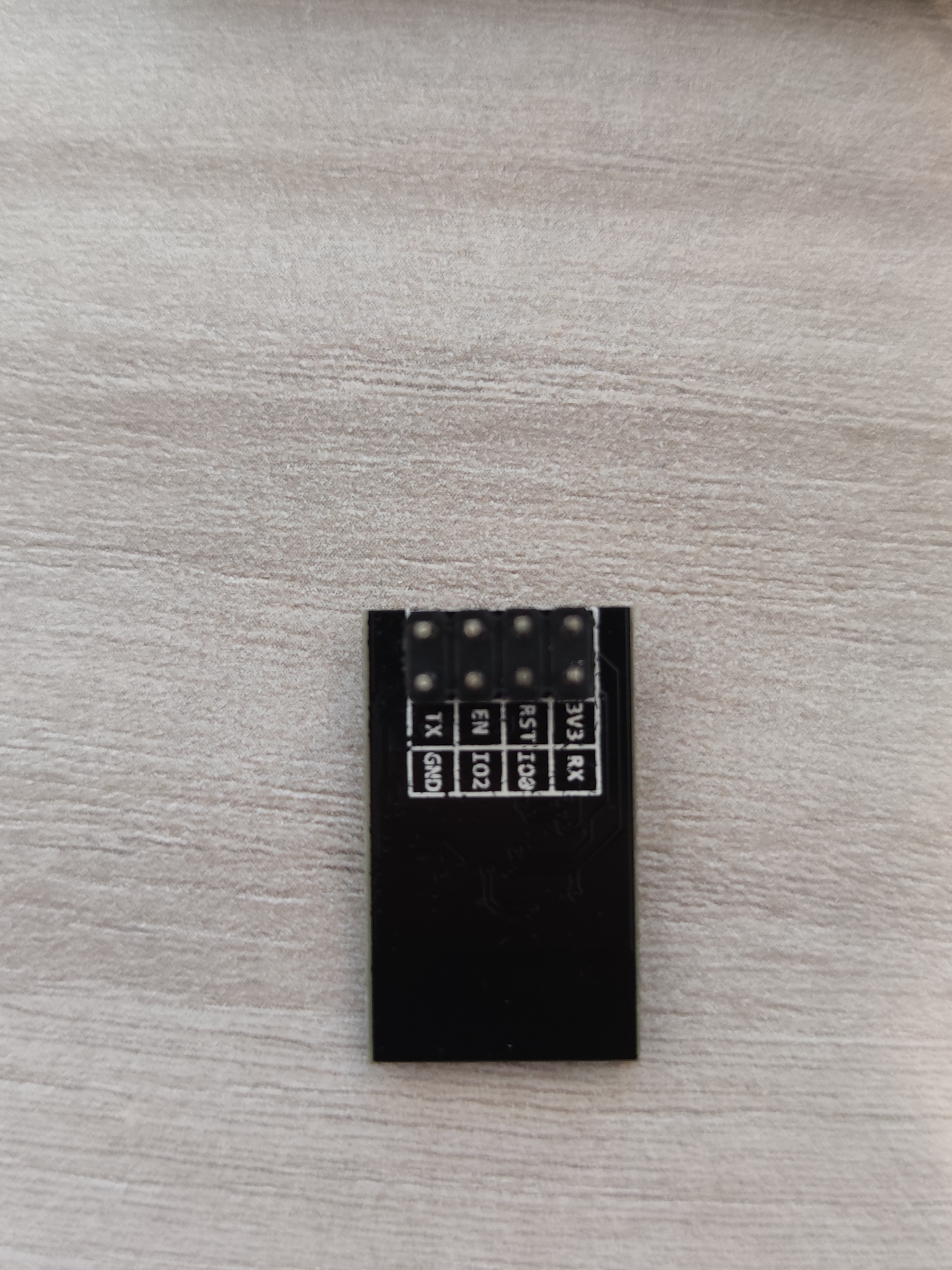
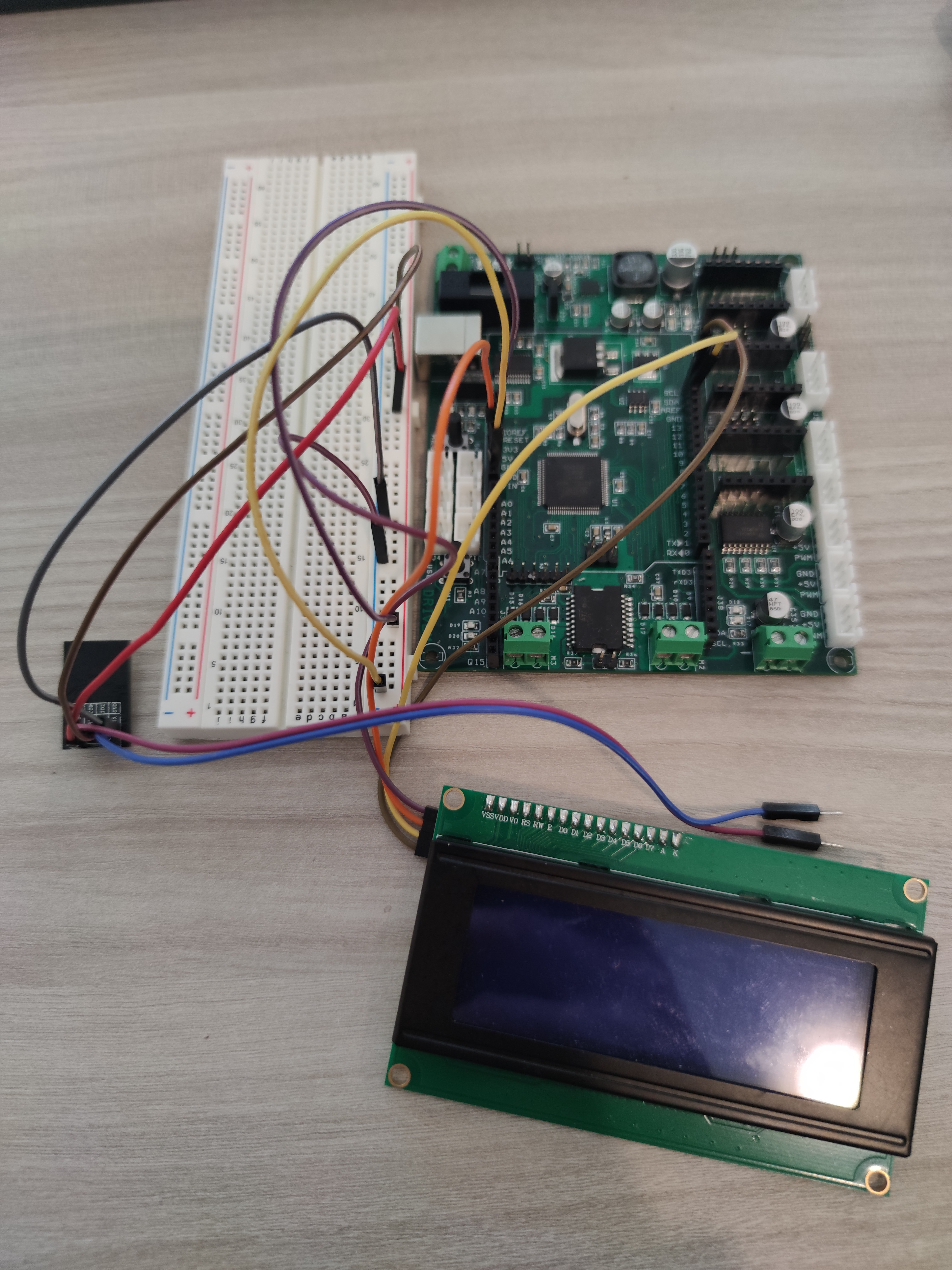
Using the schematic in picture1 and 2 we are going to connect two 3.3V power supply zones for the ESP8266
and a 5V one for the display.
The TX and RX pins of the ESP8266 must be connected once the arduinio has been programmed and with each SW update it must be disconnected.
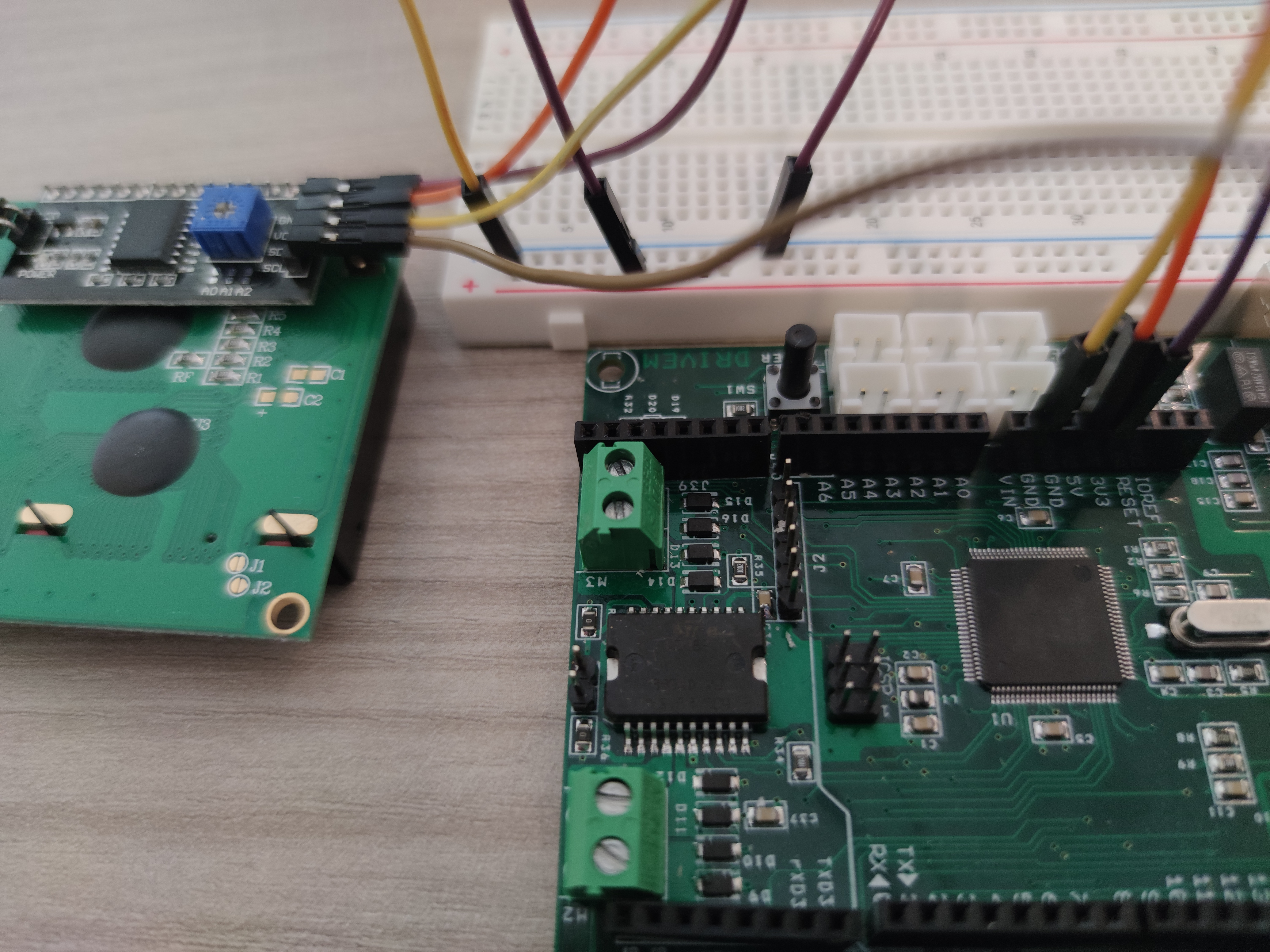
If during operation we notice that the display has insufficient brightness we can go to adjust it using the trimmer located behind the display visible in picture 3 and 4.
FW Arduino
The code needs the following libraries:
ESP8266_Lib.h which allows us to manage the ESP
LiquidCrystal_I2C.h to be able to write on the display
BlynkSimpleShieldEsp8266.h to be able to control the device from the blynk app
Wire.h for I2C communication
Before uploading the FW we must modify the following parts to connect to the Blynk application and to access the ESP8266's WiFi
char auth[] = " your token"per il token
char ssid[] = "your WiFi name"
char pass[] = "your WiFi password"