Interfacing Single Axis Gyro to Arduino
by goks_lf in Circuits > Arduino
3249 Views, 17 Favorites, 0 Comments
Interfacing Single Axis Gyro to Arduino
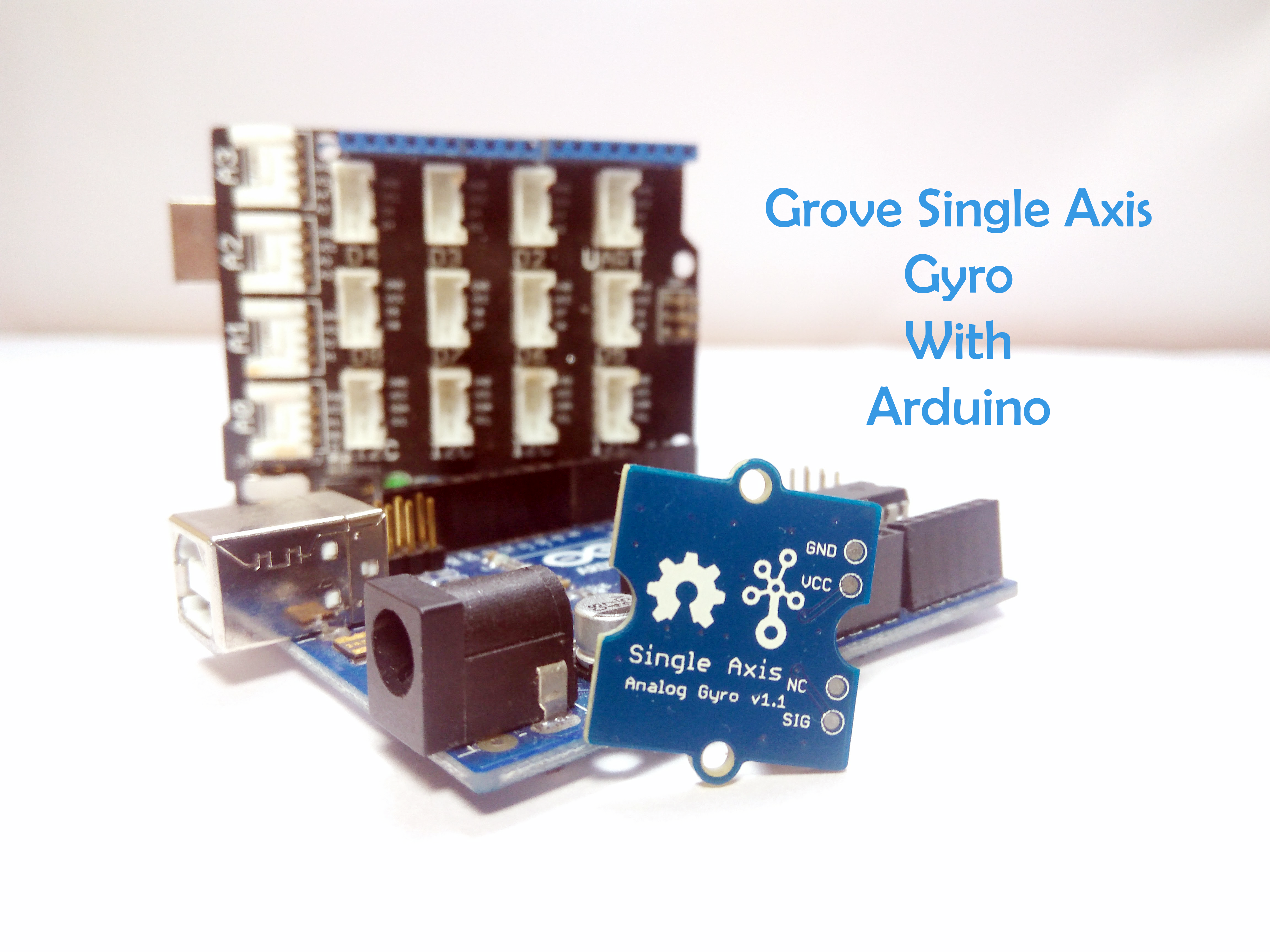
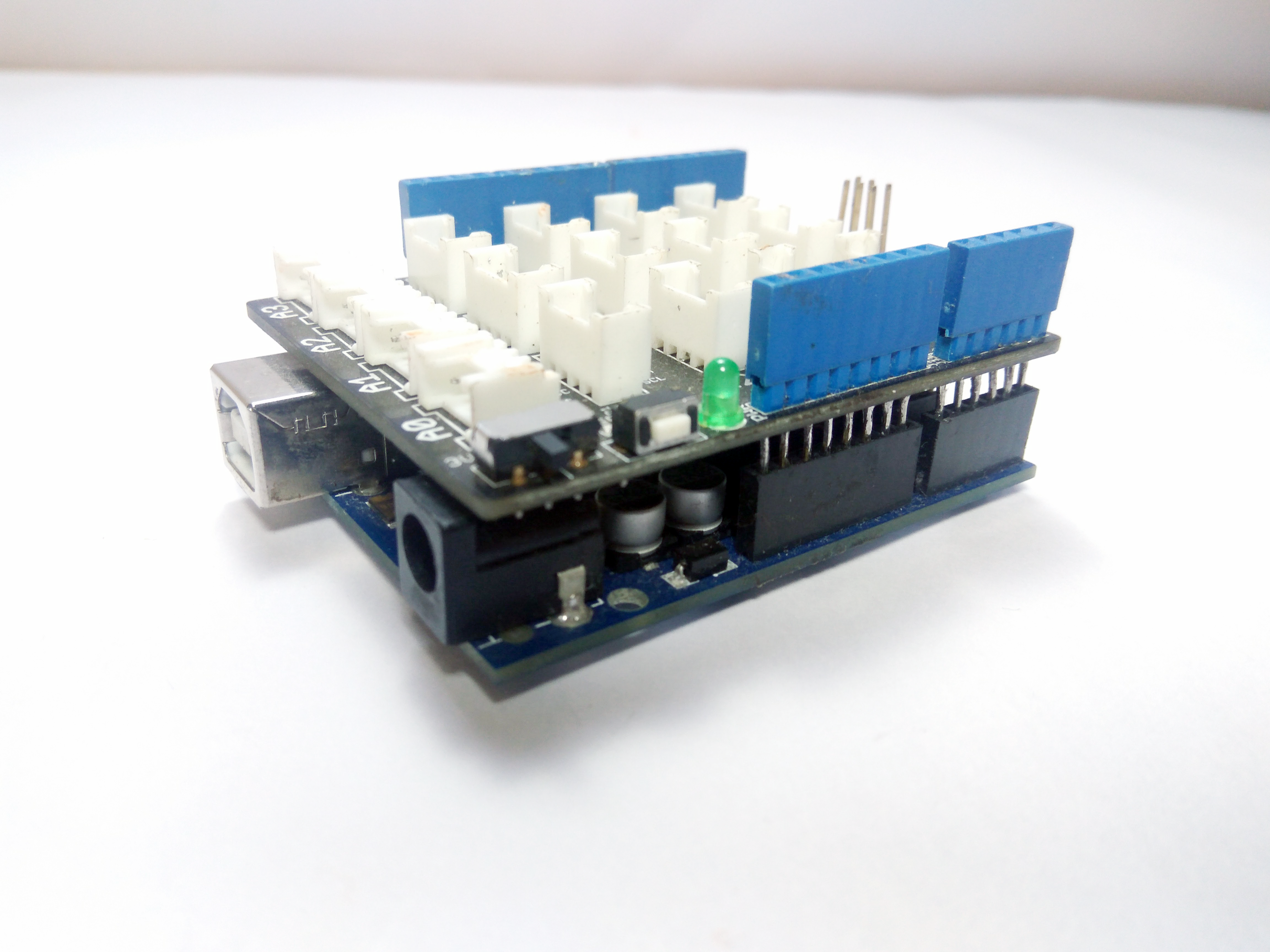
Gyroscopes or Gyro sensors are the devices that measure rotational motion. The single axis gyro sensor from Grove is a gyro that measures rotational motion in one direction only. The gyro is mainly used in measuring changes in rotational motion in small degrees, like for example in a jet, in flight stabilization systems.
In this Instructable, I'll, show you how to interface the Grove Single Axis Gyro with the Arduino Uno and notice the change in directions using the Serial Monitor.
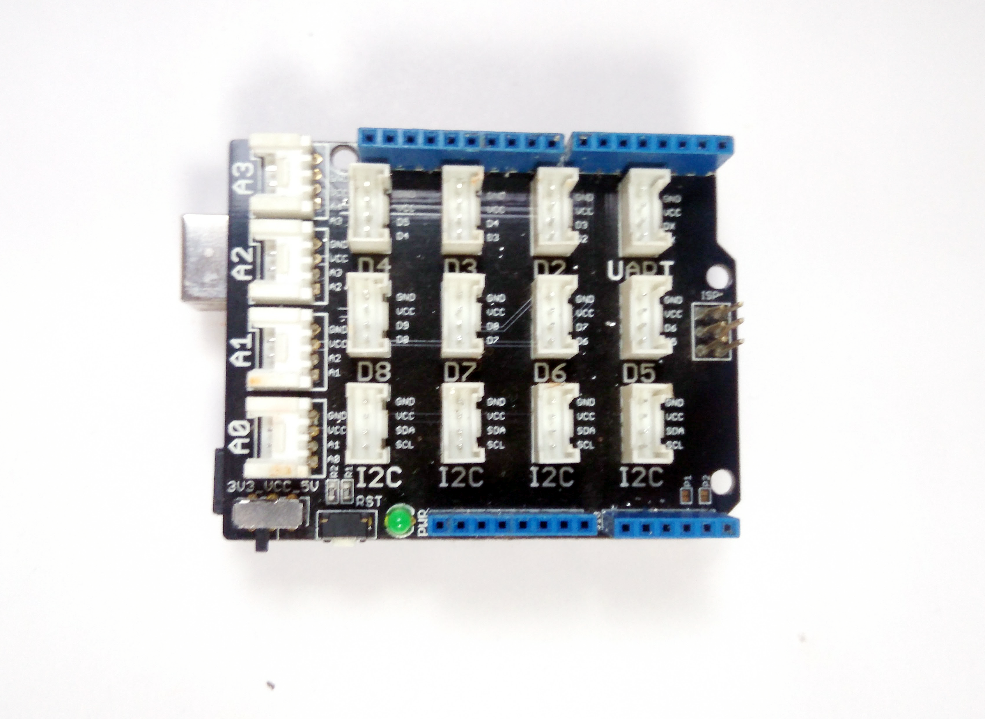
About the Grove Base Shield
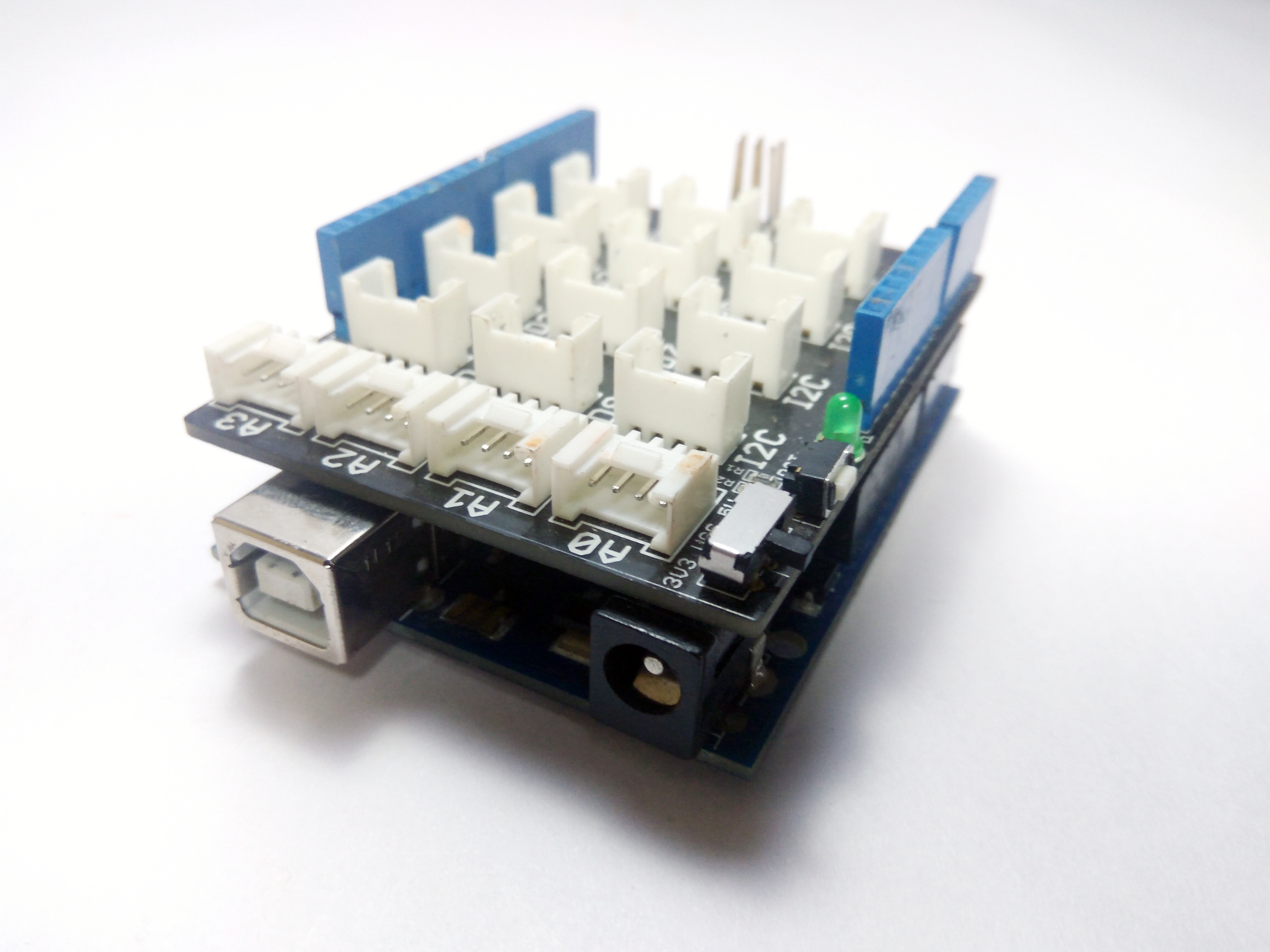
The Grove shield is basically an adapter to the Arduino which plugs into the latter and maps each and every I/O pins of the Arduino to specific ports on the shield designed for a specific function. If you examine closely, the shield will have dedicated ports for I2C(Controlling Motors), Analog Ports and Digital Ports. This is very helpful for beginners who are learning Arduino. In a nutshell, it makes it easy for the user to plug in the sensors on to the Arduino and start using them right away.
If you have a Grove Kit, you will notice that they come with all the sensors specifically designed for the Base Shield. But you can use other sensors also with the shield. In the same way, you can use the grove modules directly with Arduino or any micro-controller.
The Single Axis Gyro
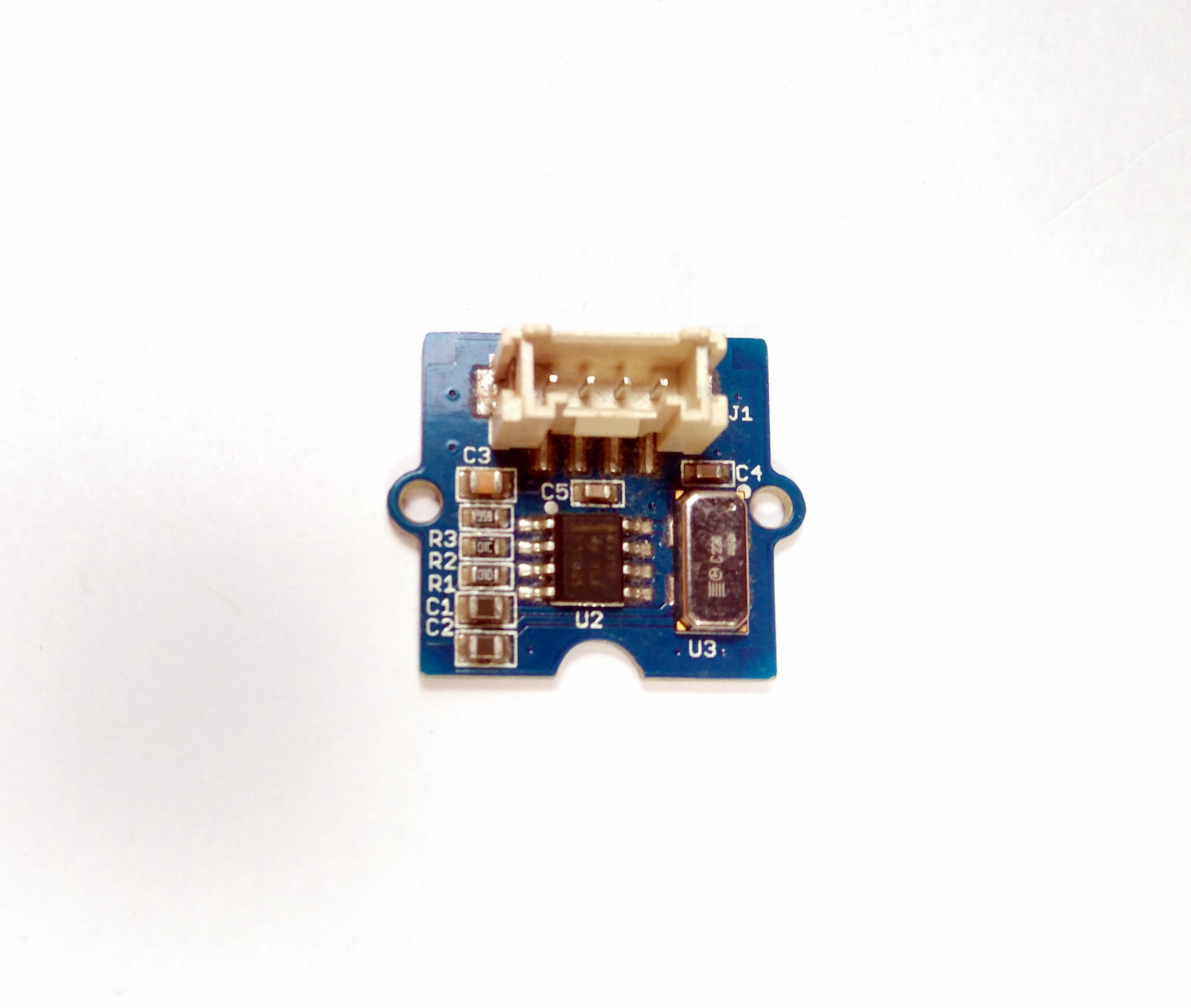
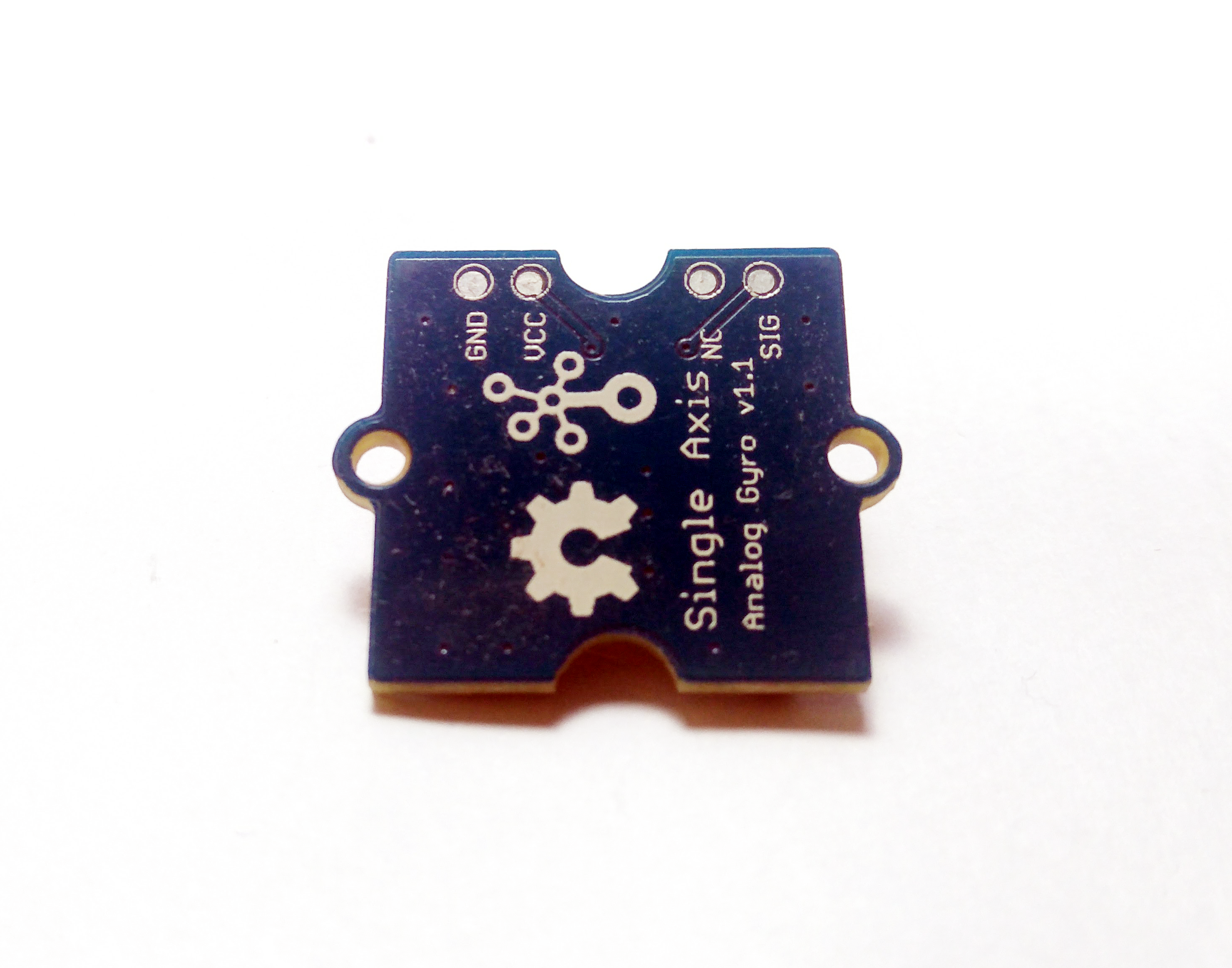
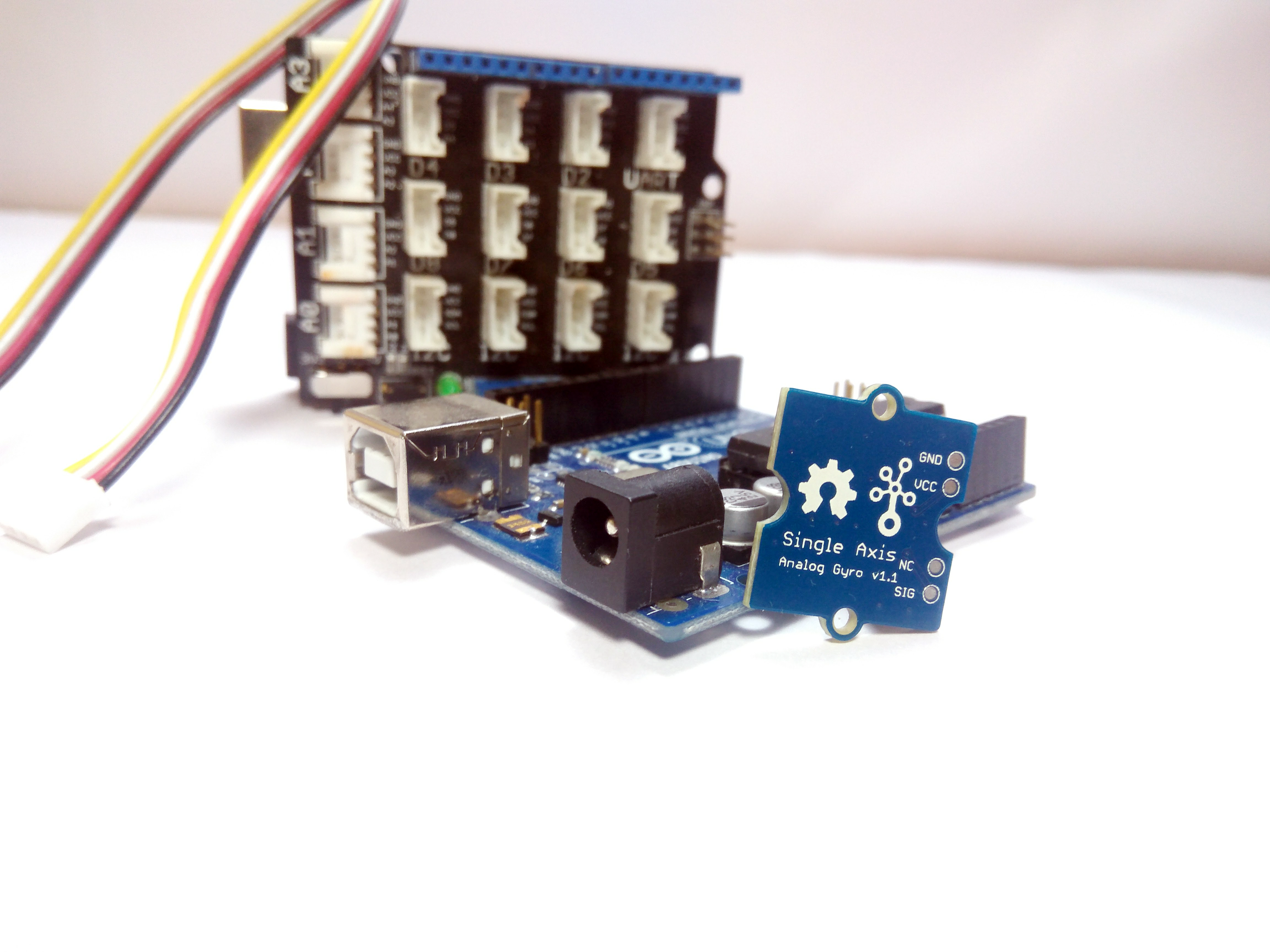
The Grove- Single Axis Gyro Sensor is based on Angular Velocity Sensor which works using the phenomenon of Coriolis Force. It can only measure the X-axis angular velocity, but it does it with a higher speed. It can be used in applications which requires position control and altitude control.
Components Required
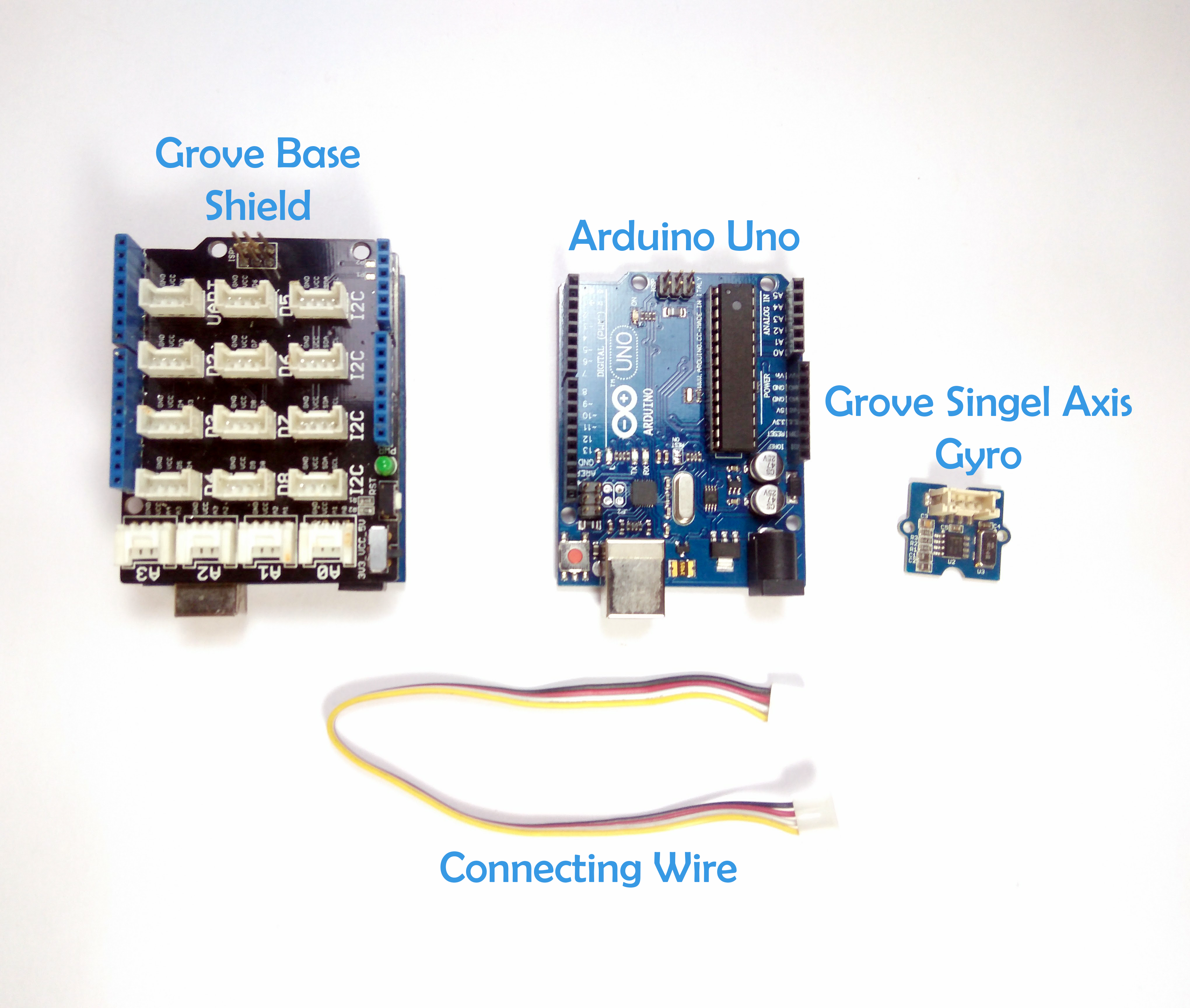
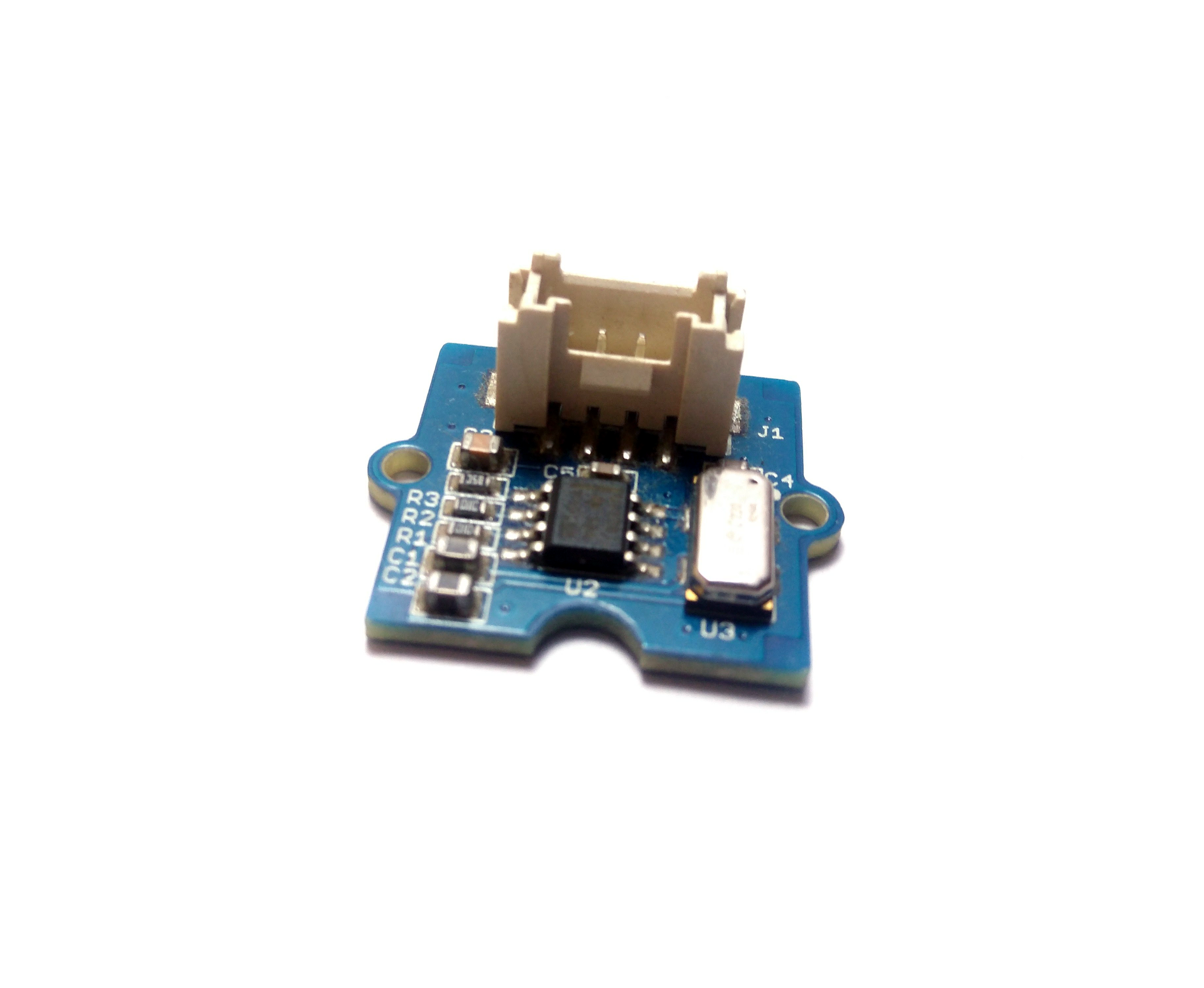
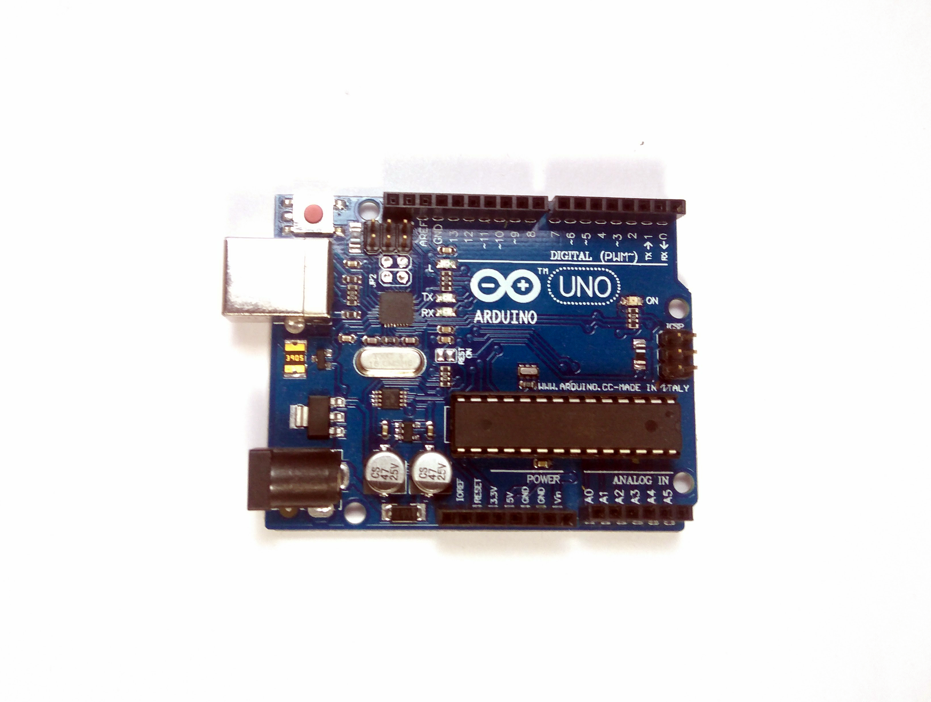
For this project, you will need:
- Arduino Uno.
- Grove Base Shield.
- Grove Single Gyro Sensor.
- Connecting Wires.
With all these in hand, let's jump into the connections.
The Connections
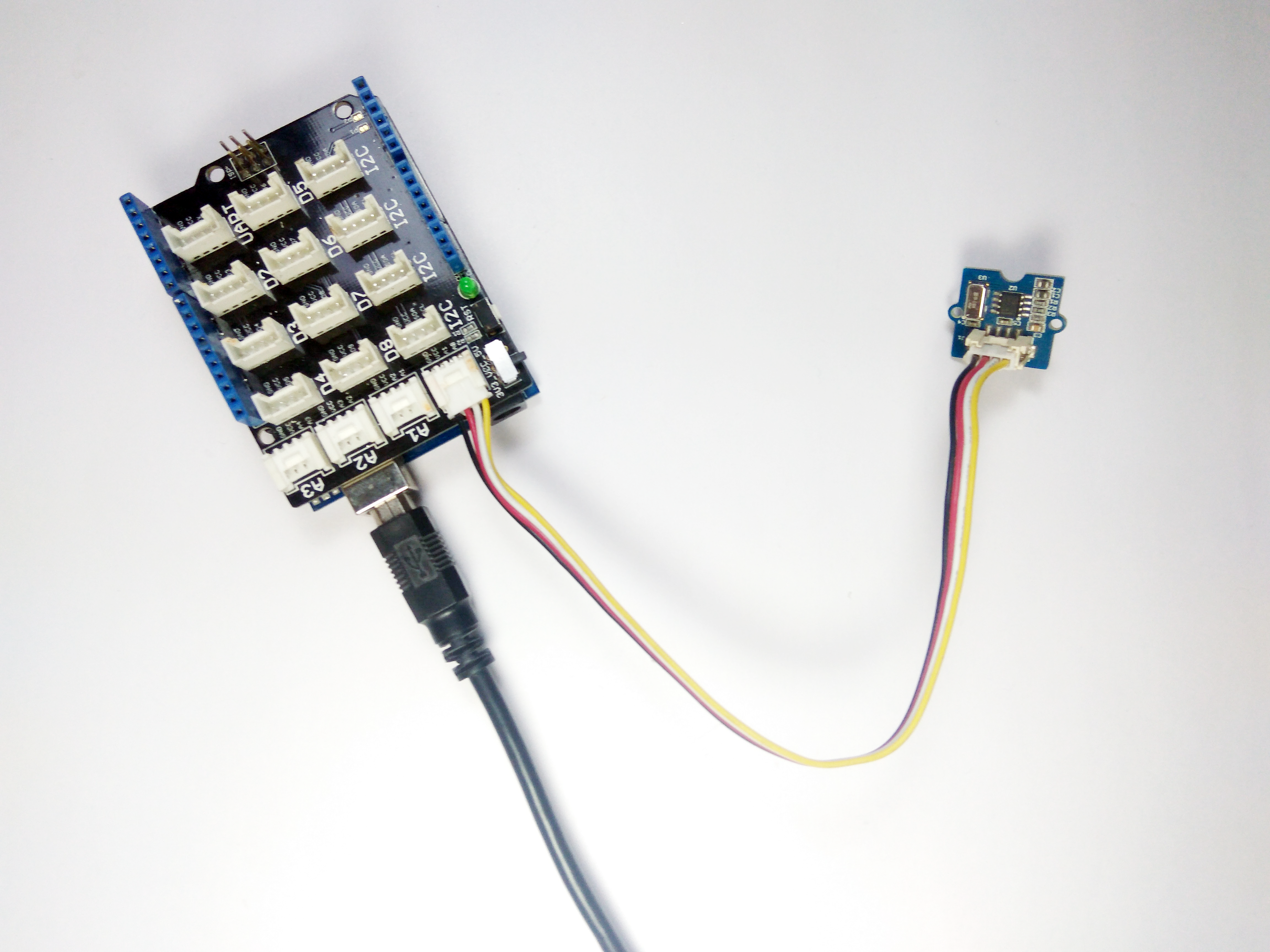
- Connefct the Sensor to a connecting wire.
- Plug in the other end of connecting wire into the Base Shield.
- Plug the Base Shield into the Arduino.
- Power up the Arduino to see the Green LED turn on on the Base Shield.
Note: You can manually connect the Sensor to Arduino or any other Micro-Controller without the Base Shield. In that case, follow the pin configuration given on the back side of the sensor.
The Code
Before the measurement of the angular velocity, a reference value (the sensor output at Angular Velocity=0) is required.
This value is 1.35V in default. But in order to get more accurate reference values, before the measurement,a calibration is necessary. In this calibration, the output voltage when angular velocity =0 been sampled 200 times, and then the average of these data will be treated as the reference value. Upload the following code to calibrate and output the Angular Changes.
int sensorPin = A0; // select the input pin for the sensor
float reference_Value=0;
int sensorValue = 0; // variable to store the value coming from the sensor
void setup() {
int i; float sum=0; pinMode(sensorPin, INPUT); Serial.begin(9600); Serial.println("Please do not rotate it before calibrate!"); Serial.println("Get the reference value:"); for(i=0;i<1000;i++) { // read the value from the sensor: sensorValue = analogRead(sensorPin); sum += sensorValue; delay(5); } reference_Value = sum/1000.0; Serial.println(reference_Value); Serial.println("Now you can begin your test!"); }
void loop() {
double angularVelocity; sensorValue = analogRead(sensorPin); angularVelocity =((double)(sensorValue-reference_Value)*4930.0)/1023.0/0.67; //get the angular velocity Serial.print(angularVelocity); Serial.println("deg/s"); Serial.println(" "); delay(100); }
Output
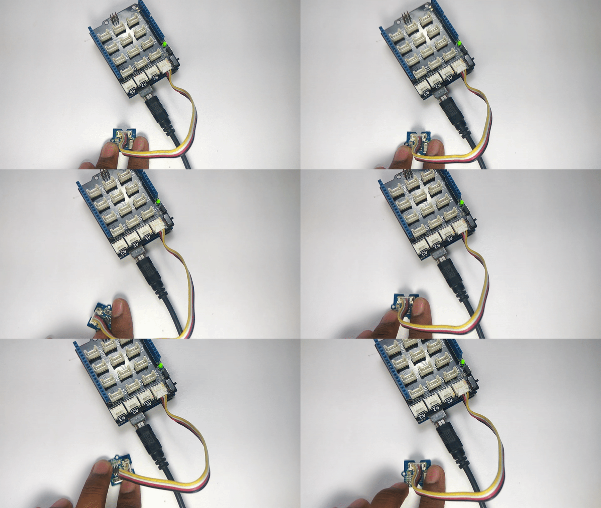
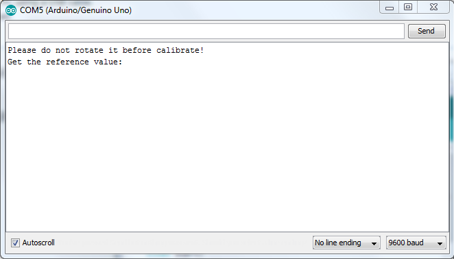
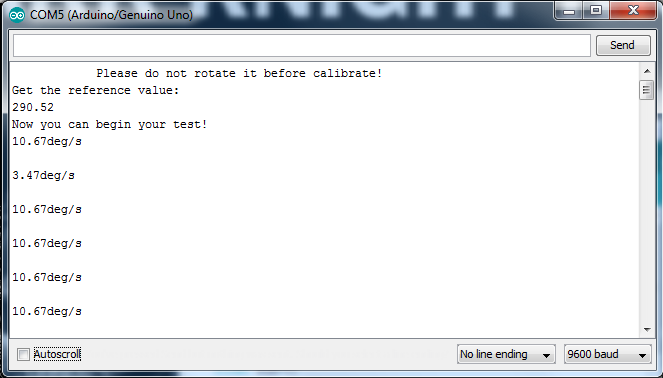
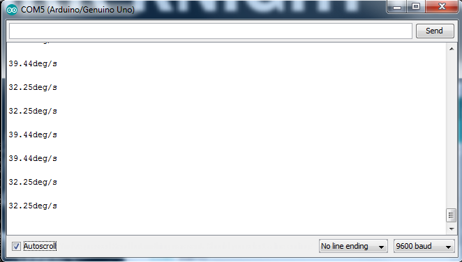
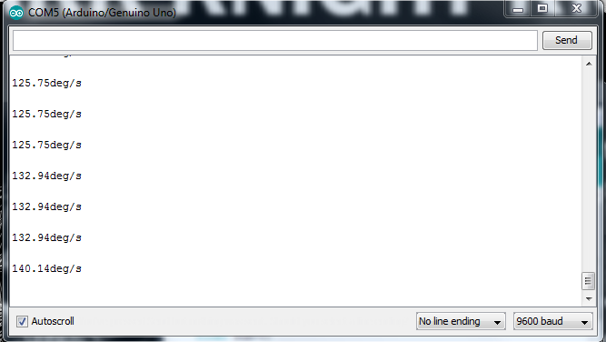
Once you have uploaded the code, place the sensor horizontally on the desktop and open the serial monitor. You will see that it says not to rotate the sensor while it is calibrating. Once the calibration is done, you can proceed with the testing.
In future Instructables, I will use this to control a servo and much more.
That's All Folks !! Stay Tuned for More!!
Keep DIY-ing !!
"If things are not failing, you are not innovating enough. - Elon Musk."