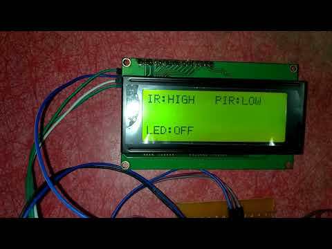
Interfacing Sensors With Arduino Using TIME DIVISION MULTIPLEXING
by Rajkumar2506 in Circuits > Arduino
3524 Views, 7 Favorites, 0 Comments
Interfacing Sensors With Arduino Using TIME DIVISION MULTIPLEXING
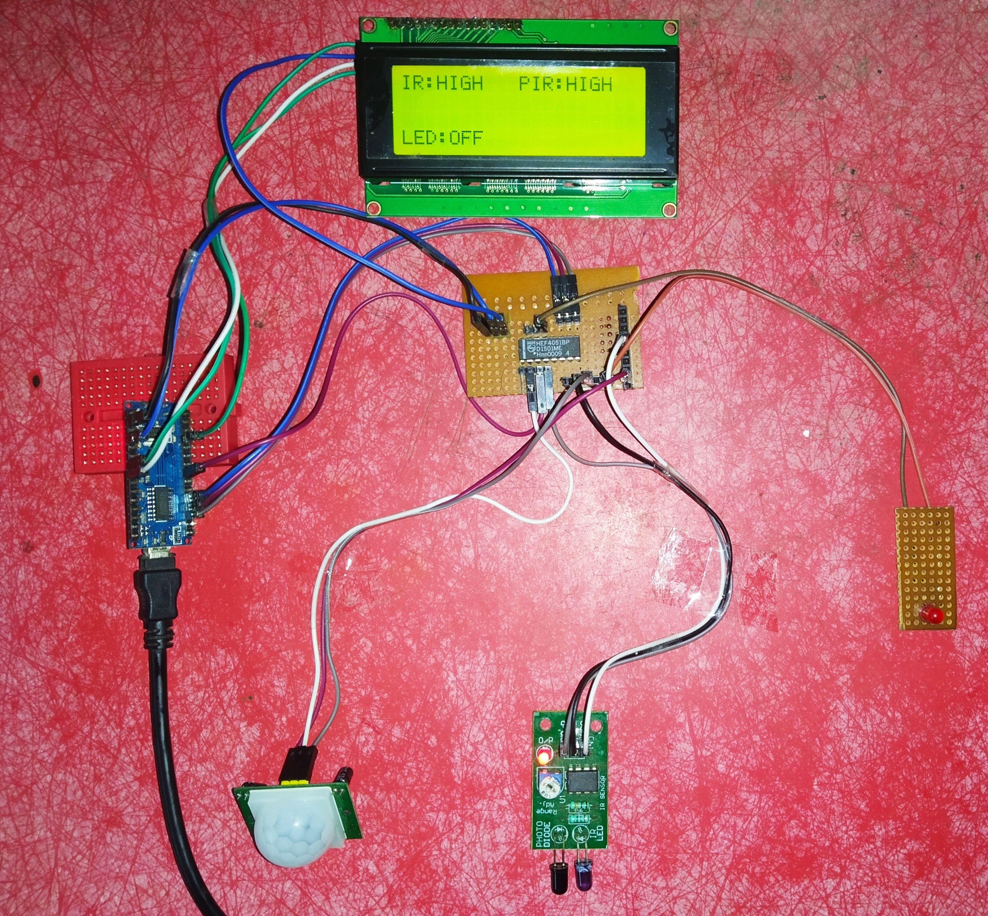
Time division multiplexing(TDM) is a method of transmitting & receiving independent signals over a common channel by means of synchronized switches at each end of the transmission line so that each signal appears on the line only a fraction of time in an alternating pattern. It is used to transmit two or more analog or digital signals over a common channel.To perform TDM i am using IC HEF 4051BP, it is a 8-channel analogue multiplexer/demultiplexer. Using this technique i am going to interface IR Sensor, PIR Sensor and an LED to Arduino by using only one digital port.
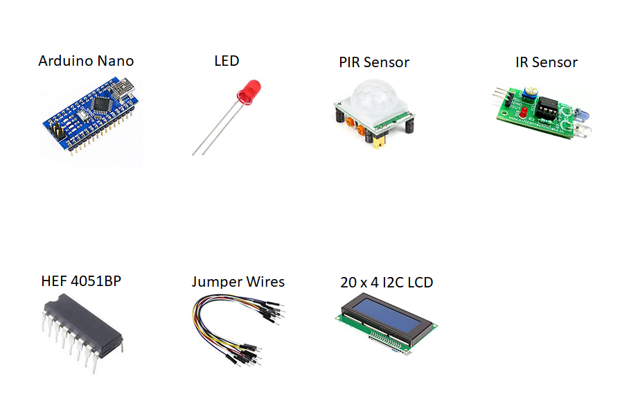
Components Required
Schematic Diagram
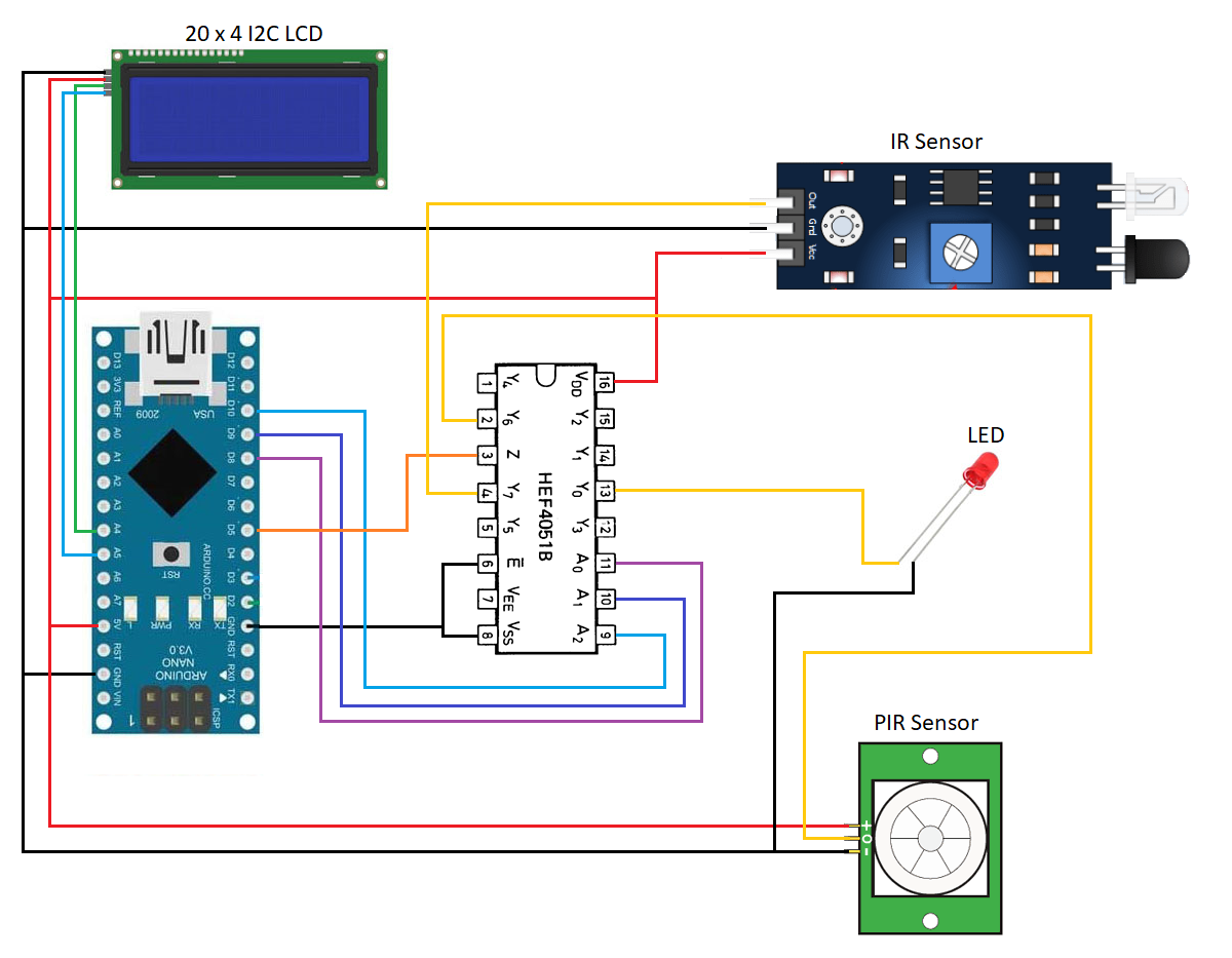
IC 4051 contains eight bidirectional analog switches each with one side connected to an independent input (Y0 to Y7) and the other side connected to a common output (Z).
Since IC 4051 contains bidirectional analogue switches we can use the ports (Y0 to Y7) for both input and output purposes.
I have used Y0, Y6, Y7 port to interface IR & PIR Sensor as input and one LED as output.
Still you can interface five more sensors to remaining ports i.e Y1, Y2, Y3, Y4,Y5.
Configuring of IC 4051
IC 4051 can be used as analog or digital multiplexer.
To use as analog multiplexer.
- Connect VDD (pin 16) to 5V.
- Connect VSS (pin 8) to Ground.
To use as digital multiplexer.
- Connect VDD (pin16) to 5V.
- Connect VSS (pin 8) & VEE (pin 7) to Ground.
To enable input & common output port.
- Connect Ē (pin 6) to Ground.
Operation of IC 4051
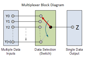
IC 4051 can be used in two modes.
- Multiplexer.
- Demultiplexer.
Multiplexer
Multiplexer consists many input and one common output. By using as multiplexer we can connect more sensors to arduino.
Demultiplexer
Demultiplexer consists one input and many output. By using as demultiplexer we can connect only one sensor and share the sensor data or signal to many Arduino or other micro controllers.
Working of IC4051 as multiplexer
I connected three components via IC 4051 to arduino as a multiplexer. As i already said IC 4051 contains 8 bidirectional analog switches. These switches should be closed to connect independent input and common output port. But out of 8 switches only one switch can be closed at a time to connect input and output port. When closing the one switch we can read the sensor connected to input of switch that we are closing. Then we close the next switch to read other sensor data and so on. When closing next switch the previously closed switch gets disconnected.
Controlling of analog switches in IC4051
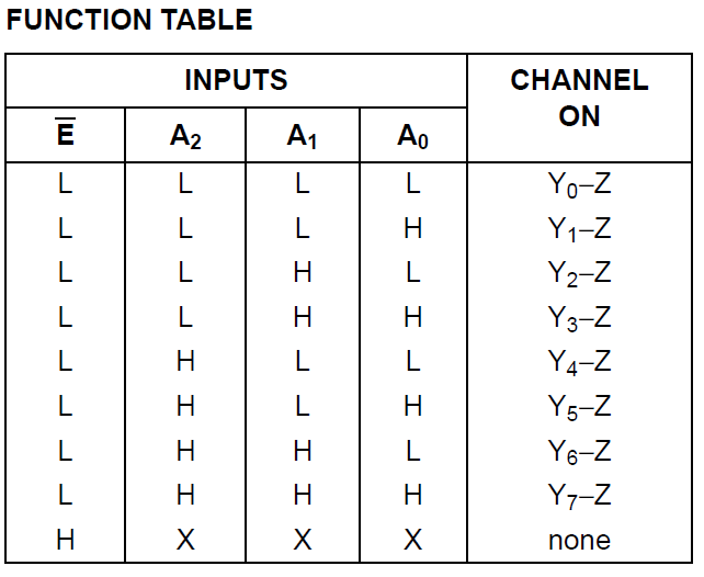
The closing of switches determines which input port is connected to common output port. We can control which switch to be closed by using select lines ( A0, A1, A2) available in IC 4051.
Please see the function table above which tells the logic level of select lines to make respective input to connect common output port.
For Example:
To use Y0 input port make the select line A0-LOW, A1-LOW,A2-LOW and now the sensor connected to Y0 input can be read at common output Z.
Note:
Common output port Z is connected to arduino D5 port. We can use digitalRead() function in D5 port to read sensor.
Use digitalWrite() function to make select lines HIGH or LOW logic level.
Arduino Code
I have attached the code.Extract and open it in Arduino IDE.
Code Explanation
I am using Time Division Multiplexing in coding with the help of IC 4051 to read sensors at different timing.
Stage 1:
I am connecting IR Sensor to Y7 input port.
Then connecting Y7 input to Common output Z via select lines by using the following code.
digitalWrite(8,HIGH);
digitalWrite(9,HIGH);
digitalWrite(10,HIGH);
Now common output Z is already connected to D5 port of arduino and i am making D5 port as input to read sensor by following code.
pinMode(5,INPUT);
lcd.print(digitalRead(5));
Stage 2:
I am connecting PIR Sensor to Y6 input port.
Then connecting Y6 input to Common output Z via select lines by using the following code.
digitalWrite(8,LOW);
digitalWrite(9,HIGH);
digitalWrite(10,HIGH);
Now the switch is disconnected from Y7 and connected to Y6. Already D5 Arduino port is declared as input at stage 1 and now i am reading PIR sensor data at D5 by using the following code.
lcd.print(digitalRead(5));
Stage 3:
I am connecting LED to Y0 input port.
Then connecting Y0 input to Common output Z via select lines by using the following code.
digitalWrite(8,LOW);
digitalWrite(9,LOW);
digitalWrite(10,LOW);
Now the switch is disconnected from Y6 and connected to Y0. Since LED is an output device positive & ground voltage is required from arduino to blink LED.So,i am making D5 Arduino port as output and blink led by the following code.
pinMode(5,OUTPUT);
digitalWrite(5,HIGH);
lcd.print("LED:ON");
digitalWrite(5,LOW);
lcd.print("LED:OFF");
In this stage, IC 4051 contains analog switch that is bidirectional.So, common output Z becomes as input port and independent input Y0 becomes as output port to arduino for the purpose of transmitting positive & ground voltage to blink LED.
Time Division Multiplexing
Arduino takes only some milliseconds to get data from these sensors via single channel that is D5 port of arduino and there is no lagging in sensor data because the data are collected in milliseconds.Since the data's collected in milliseconds from sensors it seems to us like all the sensors are working simultaneously at a time.The data's from different sensors collected in different intervals of time(milliseconds) over a single channel.So, it is called as Time Division Multiplexing.
Downloads
Output
