Interfacing I2C LCD With STM32 BllackPill Using STM32CubeIDE
by tanushree4587be23 in Circuits > Microcontrollers
38 Views, 1 Favorites, 0 Comments
Interfacing I2C LCD With STM32 BllackPill Using STM32CubeIDE

For any microcontroller project, interfacing a display unit with it would make the project a lot easier and appealing for the user to interact with. The most commonly used display unit for microcontrollers is the 16×2 Alpha numeric displays. These types of displays are not only useful to display vital information to the user but can also act as a debugging tool during the initial developmental stage of the project. So, in this tutorial we will learn how we can interface a 16×2 LCD display with the STM32F401CEUX STM32 Development board and program it using the STM32CubeIDE. For people who are familiar with STM32CubeIDE this tutorial will just be a cake walk since they both are very similar.
Brief Intro to 16×2 Dot matrix LCD display
As told earlier IDE provides a beautiful library which makes the interfacing a piece of cake and hence it’s not mandatory to know anything about the display module. But, would didn’t it be interesting to show what we are using!!
The name 16×2 implies that the display has 16 Columns and 2 Rows, which together (16*2) forms 32 boxes. One single box would look something like this in the picture below
![]()
A single box has 40 pixels (dots) with a matrix order of 5 Rows and 8 columns, these 40 pixels together forms one character. Similarly, 32 characters can be displayed using all the boxes. Now lets take a look at the pinouts.

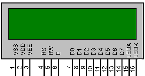
The LCD has a total of 16 Pins, as shown above, they can be categorized into four groups like as follows
Source Pins (1, 2 and 3): These pins source the power and contrast level for the display
Control Pins (4, 5 and 6): These pins sets/controls the registers in the LCD interfacing IC (more this can be found in link below)
Data/Command Pins (7 to 14): These pins provide the data of what information should be displayed on the LCD.
LED pins (15 and 16): These pins are used to glow the backlight of LCD if needed (optional).
Out of all these 16 pins, only 10 pins are to be used mandatory for the proper working of the LCD.
Supplies
- STM32 Black Pill
- LCD with I2C
- Female to Female Jumpers
- STMCubeIDE
- STMCubeProgrammer
- USB C Cable
Downloading
The liquidcrystal_i2c.h library emerges as a crucial tool in facilitating this communication, particularly when interfacing I2C LCDs with microcontrollers such as the STM32 Black Pill. By abstracting the intricacies of low-level I2C protocol implementation, this library simplifies the development process, enabling developers to concentrate on higher-level functionality and user experience. Its integration streamlines code maintenance and encourages code reusability, rendering it an indispensable asset for projects demanding dependable and efficient LCD control. With liquidcrystal_i2c.h, developers can seamlessly incorporate I2C LCDs into their projects, empowering them to craft sophisticated user interfaces and elevate overall system functionality.
download the file from the folder given below.
Configure Your STM Cube IDE


We will use STM32Cube IDE to program our STM32 board. Open the IDE and move over to a new project.
choose the STM32 BlackPill board. Then, select any column. click the 'Next' button.
PIN Mode Selection

Select Pin B6 and B7 for SCL and SDA respectively
I2C Configuration

Configure the I2C mode to I2C under Connections Menu
Configuring the Clock

Adding the Code
#include "main.h"
#include "liquidcrystal_i2c.h"
I2C_HandleTypeDef hi2c1;
void SystemClock_Config(void);
static void MX_GPIO_Init(void);
static void MX_I2C1_Init(void);
int main(void)
{
HAL_Init();
SystemClock_Config();
MX_GPIO_Init();
MX_I2C1_Init();
HD44780_Init(2);
HD44780_Clear();
HD44780_SetCursor(0,0);
HD44780_PrintStr("TANUSHREE");
HD44780_SetCursor(0,1);
HD44780_PrintStr("GUPTA");
HAL_Delay(2000);
}
Debug and Building Binary File

Click on debug (On top left corner) to generate binary file.
Open the File Created in Explorer

click on the project and click on show in system explorer.
Open STMCubeProgrammer and Connect With STM Board Via USB

Click the Open File and Paste the Copied Path

Go to Download Options

Modify Download Options and Click on "Start Automatic Mode"

DONE !


 liquidcrystal_i2c.h