Interfacing 16x2 LCD Display With STM32 Board
by anishkamal1011 in Circuits > Microcontrollers
12521 Views, 0 Favorites, 0 Comments
Interfacing 16x2 LCD Display With STM32 Board

In this project, we are going to do the interfacing of a 16x2 LCD display using a Blackpill STM32 F401CC board on the STM32 Cube IDE. STM32 is a microcontroller board based on the ARM-Cortex 32-bit processor. It has a clock speed of up to 84 MHz and various peripherals such as USB, UART, SPI and I2C.It can be used for various projects, from robotics and automation to various IoT applications.
What is a 16X2 LCD?
The term "LCD" stands for "liquid crystal display." It is one kind of electronic display module used in an extensive range of applications, like various circuits and devices like mobile phones, calculators, computers, TV sets, etc. These displays are mainly preferred for multi-segment light-emitting diodes with seven segments. The main benefits of using this module are inexpensive; simply programmable, animations, and there are no limitations for displaying custom characters, special and even animations, etc.
LCD 16x2 Pin Diagram
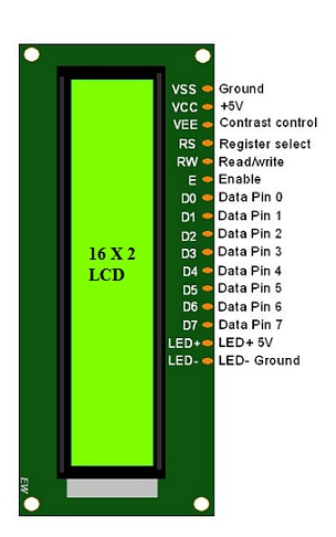
Pin1 (Ground/Source Pin): This is a GND pin of display, used to connect the GND terminal of the microcontroller unit or power source.
Pin2 (VCC/Source Pin): This is the voltage supply pin of the display, used to connect the supply pin of the power source.
Pin3 (V0/VEE/Control Pin): This pin regulates the difference of the display, used to connect a changeable POT that can supply 0 to 5V.
Pin4 (Register Select/Control Pin): This pin toggles among command or data register, used to connect a microcontroller unit pin and obtains either 0 or 1(0 = data mode, and 1 = command mode).
Pin5 (Read/Write/Control Pin): This pin toggles the display among the read or writes operation, and it is connected to a microcontroller unit pin to get either 0 or 1 (0 = Write Operation, and 1 = Read Operation).
Pin 6 (Enable/Control Pin): This pin should be held high to execute Read/Write process, and it is connected to the microcontroller unit & constantly held high.
Pins 7-14 (Data Pins): These pins are used to send data to the display. These pins are connected in two-wire modes like 4-wire mode and 8-wire mode. In 4-wire mode, only four pins are connected to the microcontroller unit like 0 to 3, whereas in 8-wire mode, 8-pins are connected to microcontroller unit like 0 to 7.
Pin15 (+ve pin of the LED): This pin is connected to +5V
Pin 16 (-ve pin of the LED): This pin is connected to GND.
Regiters of a LCD
A 16x2 LCD has 2 registers:
1.Data Registers: The data register is used to store the data to be displayed on the LCD. When we send data to LCD, it sends it to the data register and is processed there. The data is written in the register in 8 bit format.
2.Command Register: The command register stores the command instructions given to the LCD. A command is an instruction given to the LCD to do a predefined task. Example- initializing it, setting the cursor position, clearing the screen.
Supplies

Circuit Diagram for Interfacing LCD display with STM32 board
Hardware Requirements:
1.Blackpill STM32 Board
2.16X2 LCD Display
3.10K Potientiometer
4.Breadboard
5.Jumper Wires
Software Requirements:
1.STM32 Cube IDE (Downloaded from the ST Microelectronics Website).
Setting Up the STM Cube IDE
1.Open STM32 Cube IDE and create a new Project.
2.Select the board (STM32F401CCU6) and click Next.

3.Choose a name and location for your project.

Configuration the GPIO Pins
1.In the Pinout and Configuration tab of the IDE configure the GPIO Pins.
2.Select the Pins to which the LCD pins are connected and set them as "GPIO_Output".
(In our Case PA0,PA1,PA2,PA3,PA4 and PA5.)

Setting the Clock Configuration and I2C Settings
1.In System Core menu , select RCC.
2.Set the mode of High speed clock and Low speed clock to "BYPASS Clock Source".

3.Now, in Clock configuration Tab

4.Now, in the Connectivity menu , select I2C1 and do the following settings.

Writing the HAL Code
1.After doing all the above steps, open the main.c file.
2.Now,write the following code.


3.In the while loop statement, write the following code.

4.Now,Build the project to check if there are any errors.
5.Next right click on the project , open properties > C/C++ Build > Settings > MCU Post Build outputs and convert the project into Hex file.

Uploading the Code on STM32 Board
1.After converting to Hex file, open STM32 Cube Programmer.
2.Open the HEX file in Cube Programmer.

3.After connecting the Board to your laptop or computer, click on Download and the code will be uploaded on the board
and LCD will start interfacing.

SUMMARY
In Conclusion , In this tutorial I have explained on how to interface a 16X2 LCD display with Blackpill STM32 microcontroller Board. In the Software requirement I have used STM32 Cube IDE and STM32 Cube Programmer (for uploading the code to the board) for the implementation of the task. You can also use Arduino IDE for completing this task.