Interactive Sliding Visualizer
by ee27nstanford in Circuits > Gadgets
8155 Views, 80 Favorites, 0 Comments
Interactive Sliding Visualizer
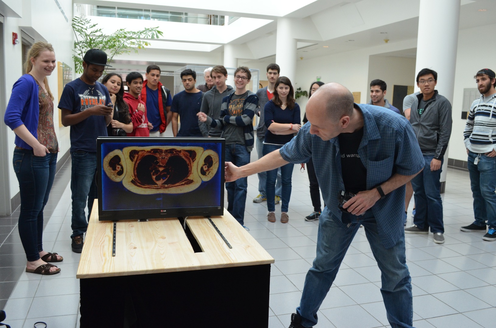
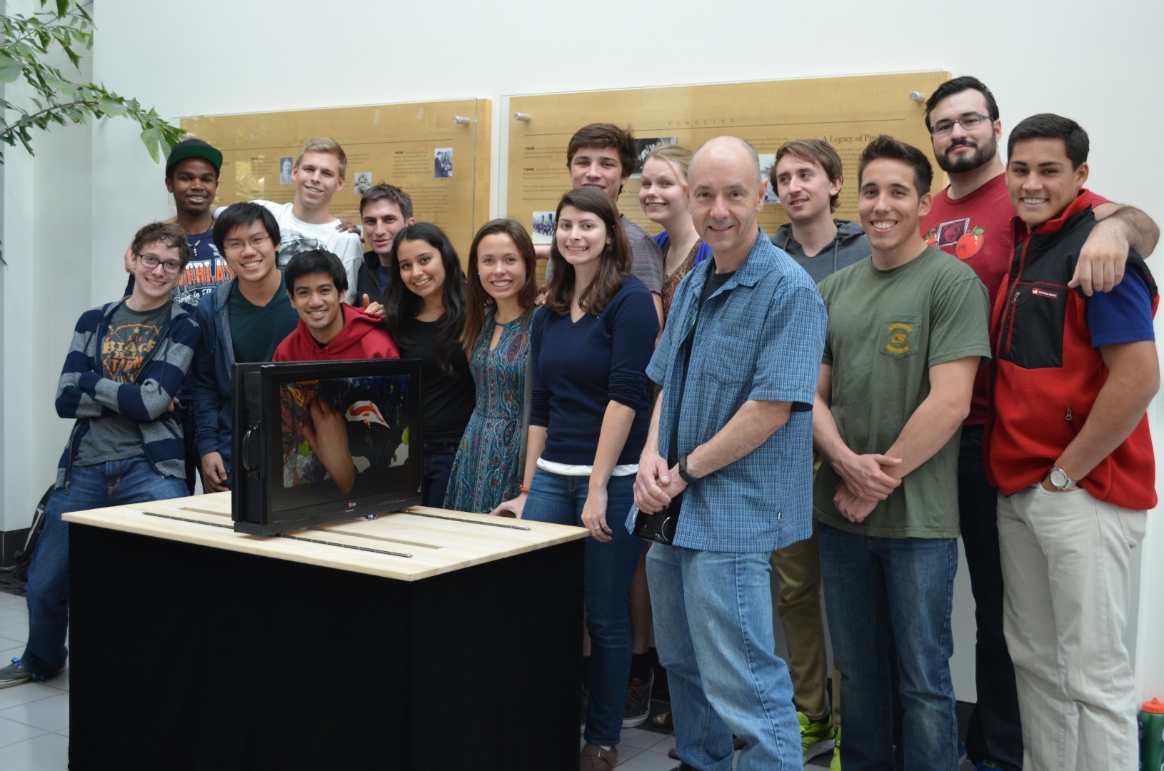
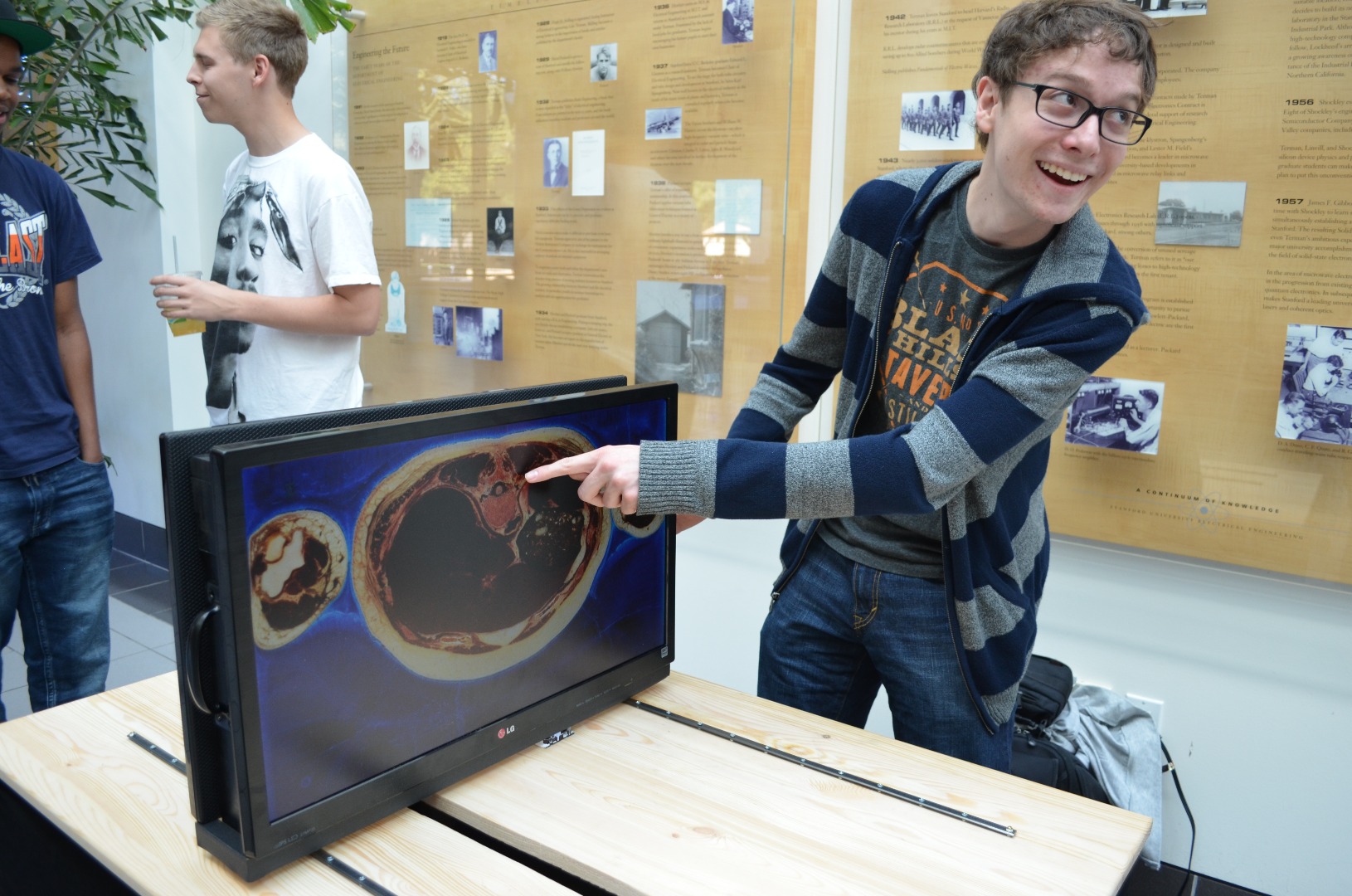
This project is an interactive sliding visualizer. It is a tool that can be used to scroll through either time or space.
Demonstration Video:
We used it to visualize a 3-dimensional cadaver image set and figuratively "slice" a body. We also used it to visualize a time lapse of a painting. What makes this project unique is it's interactive nature - you can physically scroll through either time or space. This project was created by a group of 14 Stanford undergraduates in EE27N (Electronics Rocks!), and\ introductory seminar in Electrical Engineering. We see this visualizer having many other potential applications, and are excited to see the Instructables community's response to it.
The construction consists mainly of a table and sliding rail system, a sliding platform on which the monitors will sit, and the actual dual-monitor system itself.
Tools and Materials.
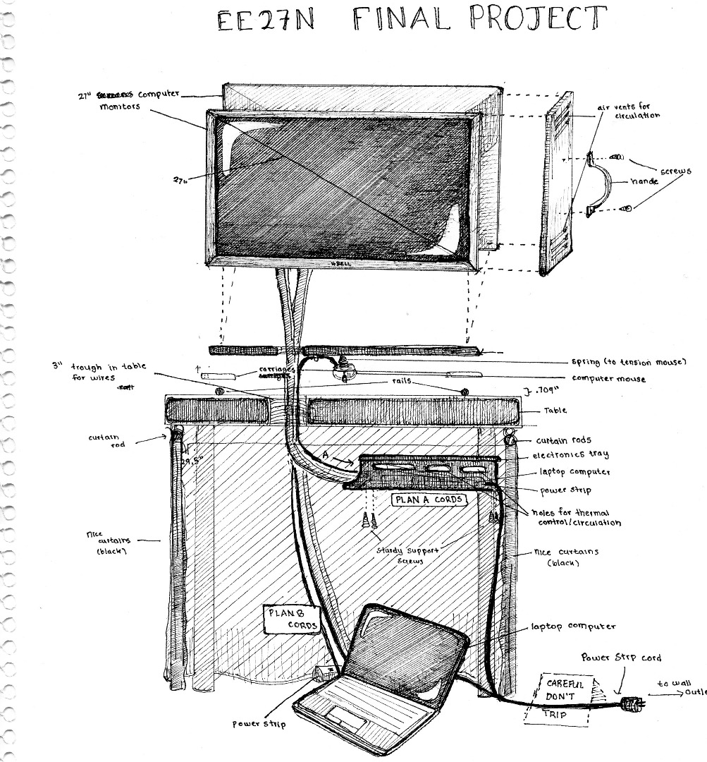
Materials:
1" Thick wooden base (4” x 25”)
1" Thick wood for handles and frame ((2) 2.5” x 11”, (2) 2.5” x 2.75”, (1) 2.5" x 23.5”)
(1) Wooden table (from Ikea)
(2) HD IPS monitors (*Power supplies included)
Relatively high performance gaming mouse
(2) standard HDMI Cables(6ft) *Only 1 needed if using PC
(2) HDMI 90 degree adapters (male to female) *Only 1 needed if using PC
(1) lightning bolt to HDMI adapter (If using Mac) or 1 VGA cable if using PC
Miniature Track Roller Cartridges with steel wheels (2), Guide Rails (2, 36.5”) and Rail support spacers (38)
(2) Drawer Handles
(4) 12mm (¾”) round head wood screws (for putting on the end of the rails to stop the monitor base from rolling off of the rails) with (4) washers
(34) ¾” flat head screws (for attaching the rails to the table)
(2) 1” round top, phillips-head machine screws (for attaching the monitors to the base) with (2) washers
(12) 10mm round head wood screws for attaching the L-bracket to the base and sides
(6) 10mm round head wood screws for attaching the top part of the frame
(4) L-brackets
(2) Large L-brackets
HD Camera (for content generation; unnecessary if using existing image sets)
(1) Surge Protector with minimum 3 inputs (2 for monitors, 1 for operating platform (Ex. macbook pro) )
OPTIONAL: 6 yards of micro velvet black fabric (to cover table - get more or less depending on size of table)
OPTIONAL: Black spray paint
OPTIONAL: Small package of zip ties (for cable management)
OPTIONAL: Roll of Gaffer’s tape (for aesthetics)
Tools:
Table saw
Drill press
Jig saw (used to cut a groove in the table to manage the cables)
Hand drill
Staple gun and staples (unnecessary if no curtain will be used)
Construct Table
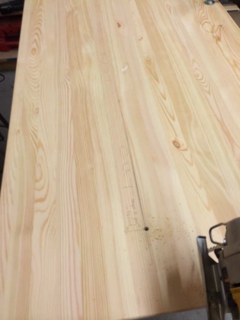
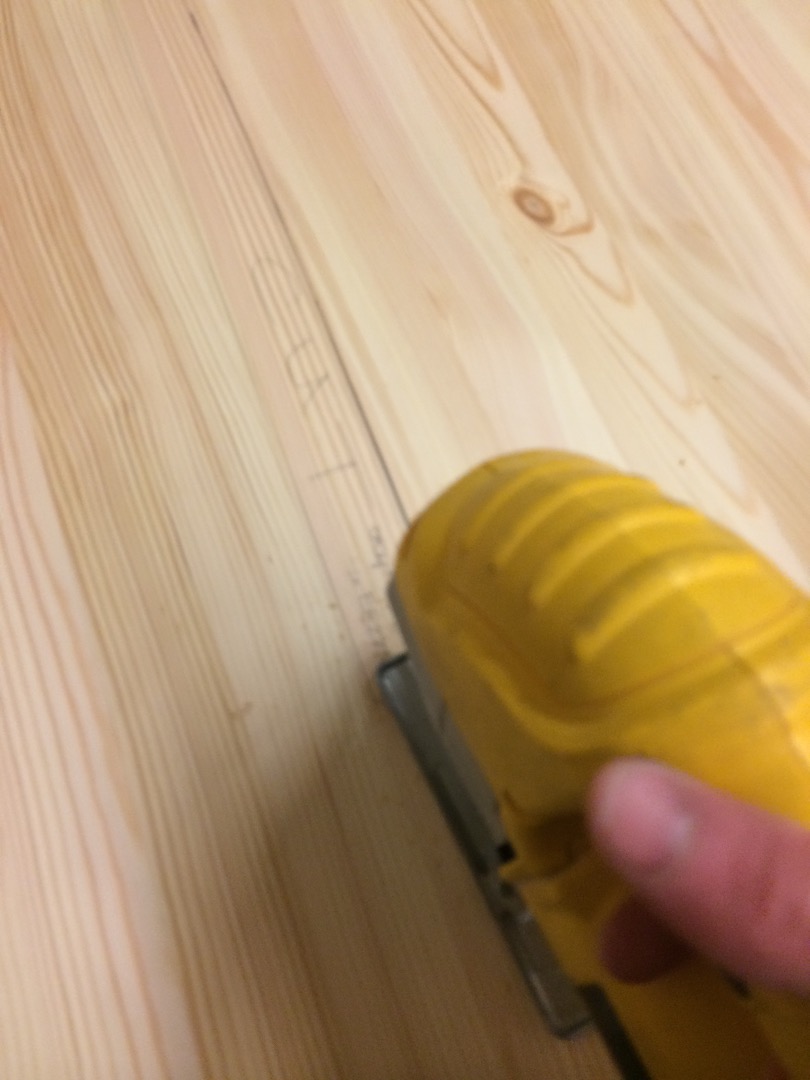
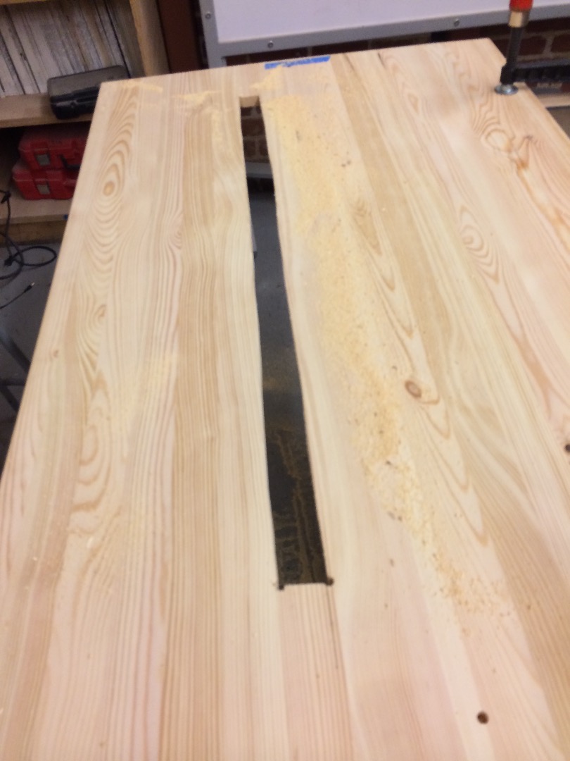
In order to prep the table for mounting, we highly recommend performing this first step before assembling the table.
Cut a Rectangular Groove in the Top of the Table
We cut a groove 37 inches long (centered) and 2 inches wide parallel to the long end of the table. This groove should be slightly offset from the center of the table, because the manner in which the monitors will be mounted prevents the cables from dropping straight down below the monitors. The purpose of this groove is to give the (2) HDMI cables, (2) power supply cables, and (1) mouse USB cable a place to hang down from the dual-monitor system, giving them the flexibility to slide along with the monitors without being visually displeasing and preventing any hang-ups or snags.
We cut this groove by drilling 4 holes into the table at the corners of the planned cut and using a jig saw to cut the rectangular groove.
Assemble the Rest of the Table
This should be pretty self-explanatory, IKEA's provided instructions are fairly detailed.
At this point, the sliding rails should remain unattached in order to allow for precise measurements described in a later step.
Cut/Prep Monitor Platform
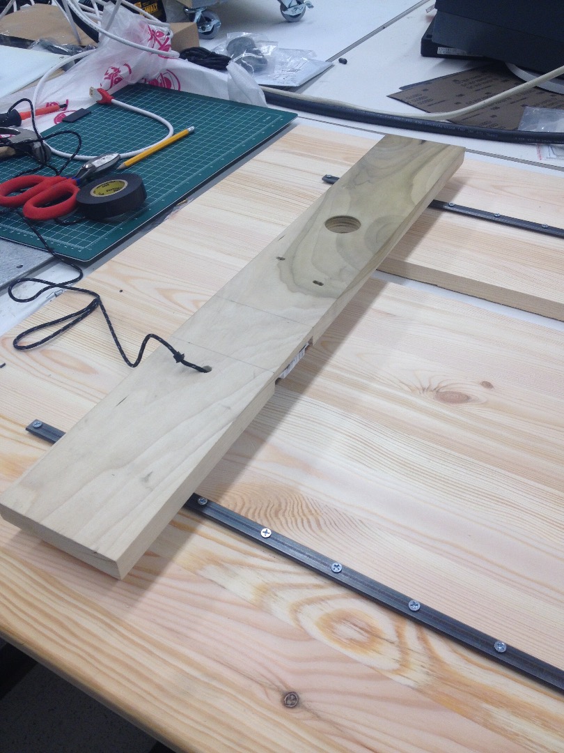
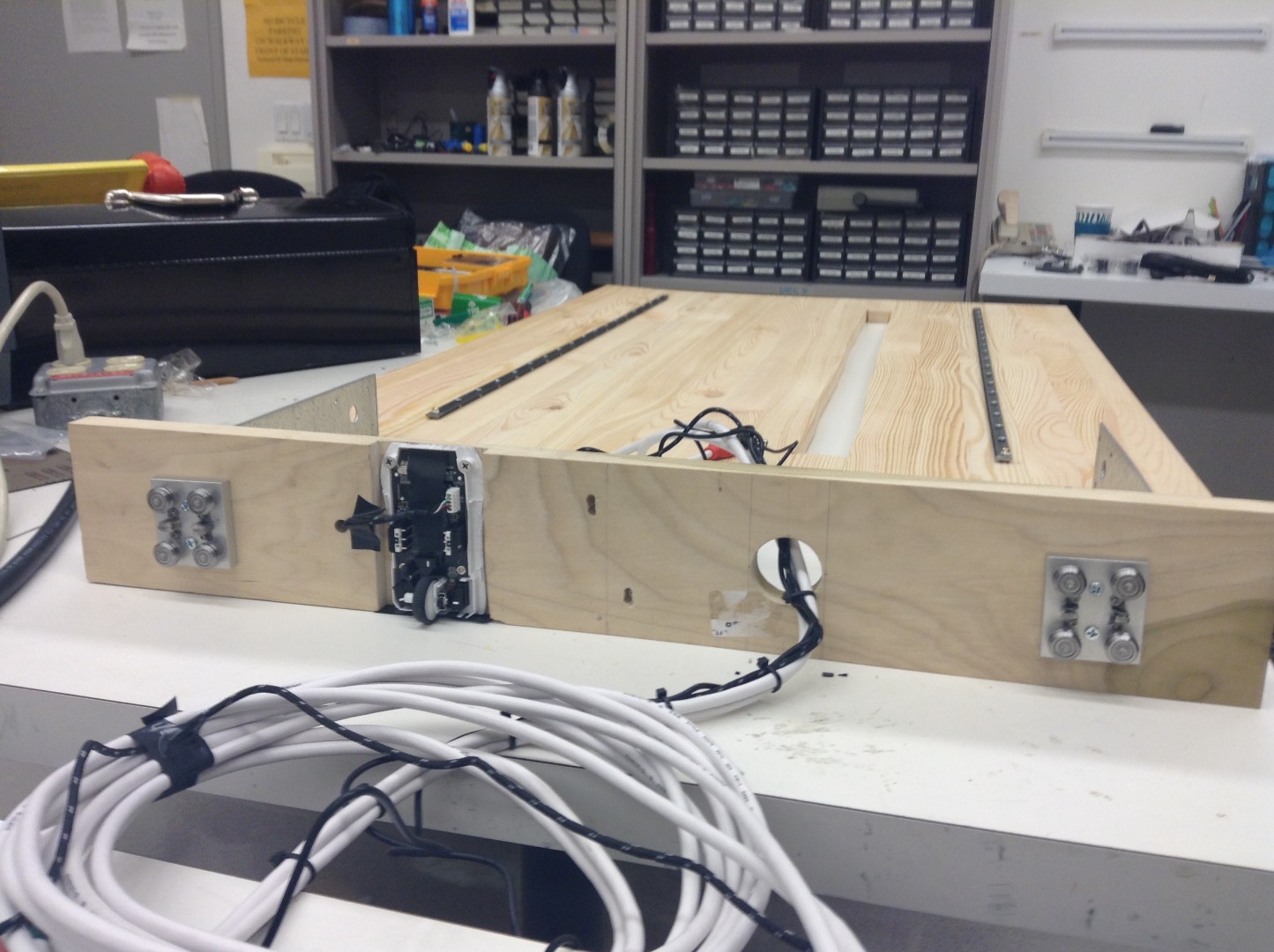
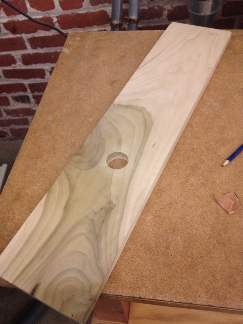
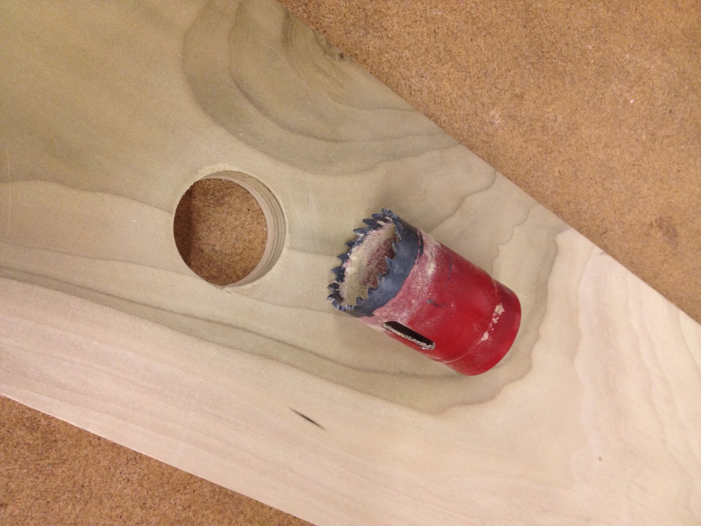
The next step is to cut and prep the platform that will hold the two monitors. This platform will later be attached to the two sliding cartridges, which are designed to slide smoothly on the two rails.
Cut Platform
We cut a rectangular piece of wood 4 inches by 25 inches from a 1-inch thick piece of wood.
Cut Hole in Platform for Cables
We then cut a hole 1 1/2 inches in diameter so that it is above the cable slot, and centered in the platform (see picture). This hole will be used to pass the bundled cables ((2) HDMI, (2) monitor power sources, (1) mouse USB) through the platform and down into the rectangular slit cut into the table. It is important to cut this hole so that it will line up with the rectangular slit in the table to avoid any friction along the edge. It may be beneficial to lay the platform centered on the table, and visually mark where this hole should be cut so that it is directly above the slit in the table.
Cut Hole and Slot for Holding the Mouse
The last step for preparing the platform is to cut an indent on the bottom of the platform (we used a table saw) in which the mouse will be mounted. This can be placed anywhere that won't interfere with the other cables or the rail system, but we recommend that you cut this indent equidistant from the center of the platform as the larger cable hole (see pictures). The reason this slit is needed is because the distance between the bottom of the platform and the surface of the table is not large enough for the mouse to fit between (This distance is only the height given by the rail spacers, rails, and cartridges). Therefore, this indent must be cut from the platform to give the mouse the space it needs. Depending on which mouse you use, the depth of this indent will vary. For reference, the rail+rail spacers+cartridge system is 0.709 inches high. In our case, after modifying the mouse (described in a later step), we needed an extra 1/2 inch of clearance.
Lastly, you will need to cut a small hole somewhere near the mouse groove, large enough to pass the mouse's usb cable up through the platform to be joined with the rest of the cables between the monitors.
Construct Rail System
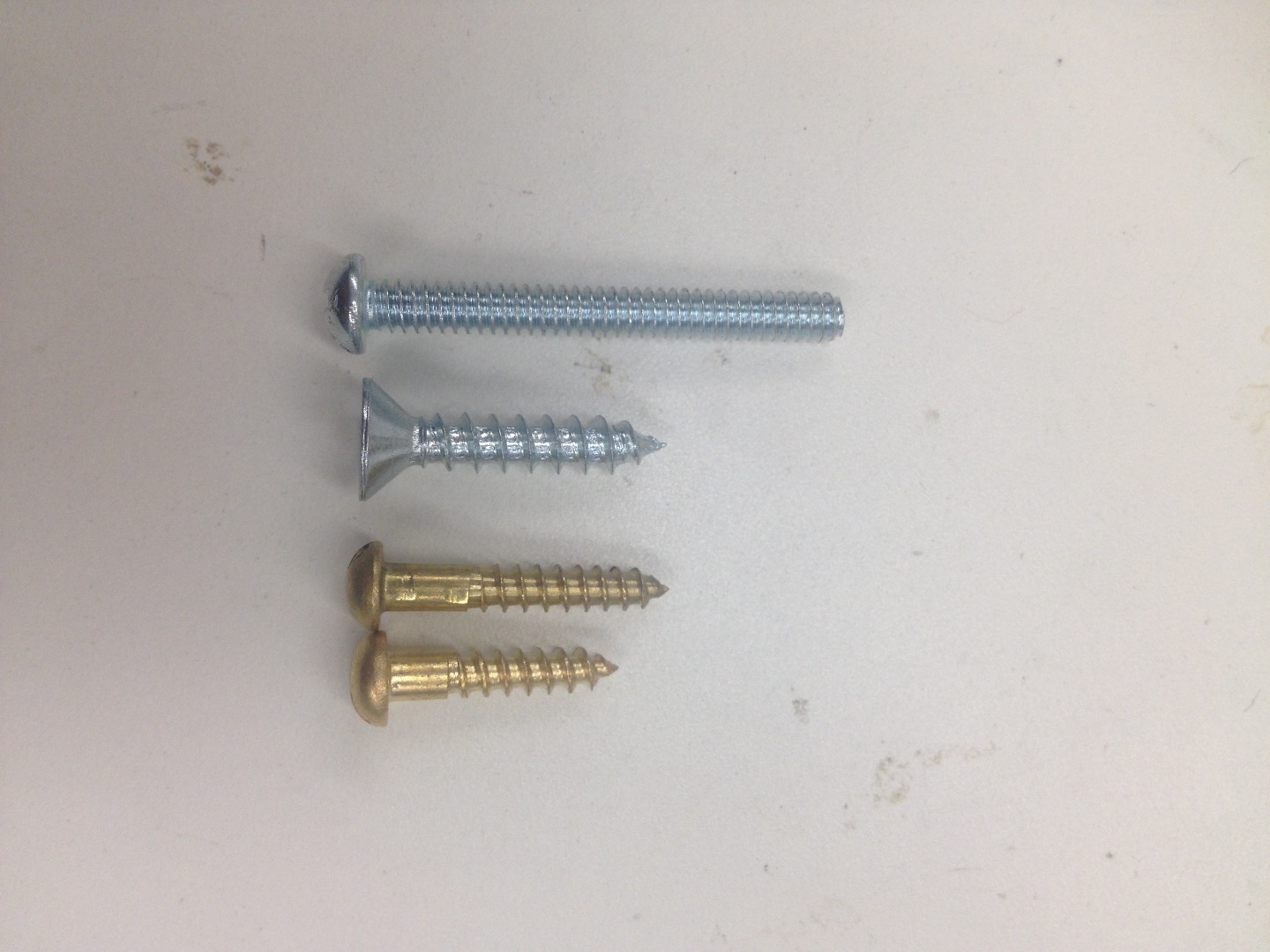
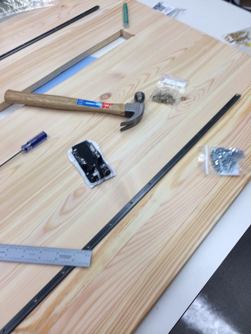
This step requires crucial attention to detail, and any significant error could jeopardize the overall success of the project. But no pressure! Just be sure to keep in mind that the rails MUST be parallel.
Put Sliders onto Monitor Platform
In order to attach the sliders, we first attached one slider to a piece of wood, doing our best with a ruler to make it straight. We then attached the second slider, but fixing it only at one point. We then placed the entire base on the rails so the sliders were perfectly aligned, and then fully fixed the second slider in place, to ensure the sliders were aligned.
Attach Rails on Table
rail size = (36.5" long, 0.5" wide)
It is very important that the rails are in line with one another. We attached them with 3/4 inch long screws and the spacers. We attached one rail to the table and then slowly and carefully attached the other one, making sure that it was exactly parallel. It's helpful to make sure your measurements are exact before attaching every screw.
Modify and Mount Mouse
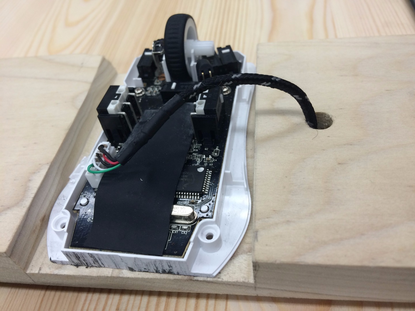
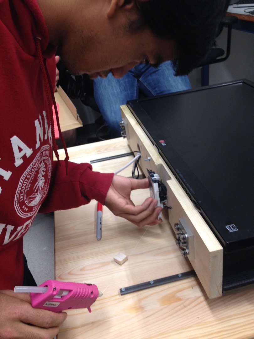
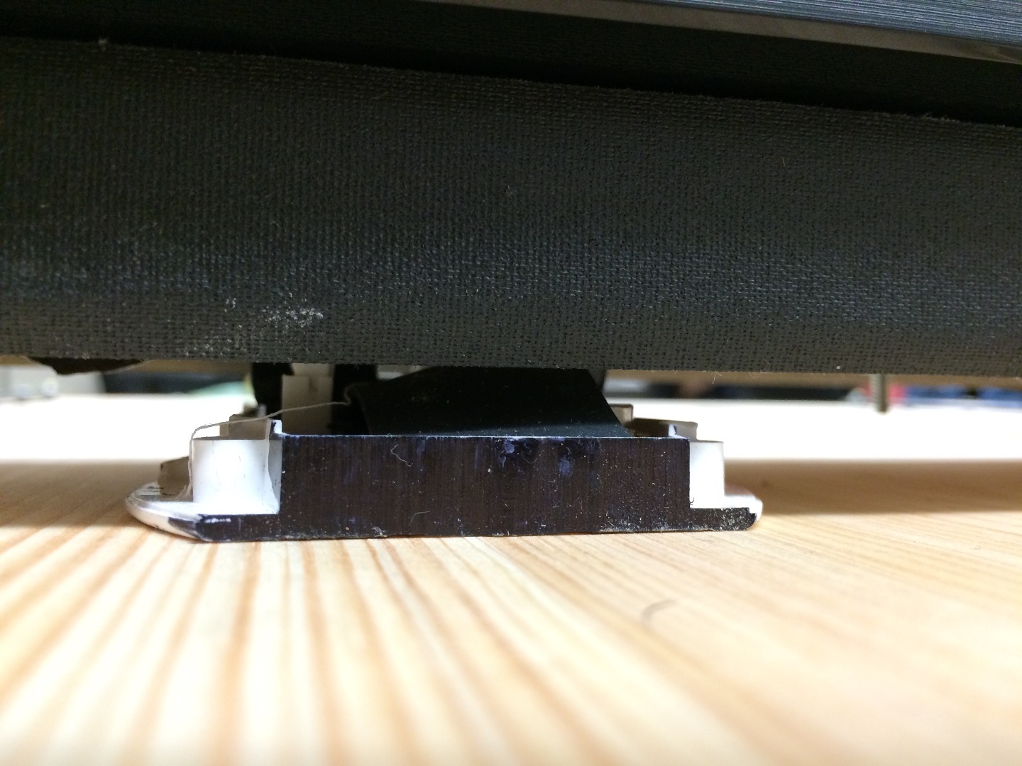
Before embarking on this next step, we should explain a few details:
When we set out to implement the mouse as the position-tracking device for the monitor system, we originally intended to use the scrolling wheel to track motion. As seen in the first picture, we mounted the mouse into the bottom of the monitor platform with the wheel facing outwards, that way once the platform is mounted onto the rail system, the wheel was making solid contact with the surface of the table. However, during a test run we noticed that the scroll wheel of the mouse did not perform well when the monitors were moved at a relatively quick speed across the rails (the images skipped and position did not accurately register). Therefore, we decided to flip the mouse over and use the optical-laser as the position encoder, which was far more accurate and could handle greater speeds.
The directions below describe how to mount the mouse with the intent of using the optical laser as the position encoder.
Disassemble and Minimize Size of Mouse
We disassembled the mouse by using a screw driver to remove screws holding the plastic encasing on the device. The typical mouse has 4 screws on the bottom of the mouse (this is the case for the SteelSeries mouse listed in the materials). Take off the top of the plastic body of the mouse and remove the mouse wheel. Just simply pop it out of its hold. We then trimmed the edges of the plastic base off of the mouse using a bandsaw (DO NOT CUT THE ELECTRONIC BOARD). This allows the mouse to fit nicely within the edges of the platform with no overhang. We also covered the cut surfaces with Sharpie.
Mount the Mouse to Bottom of Platform
As shown in the pictures, the altered mouse was then hot glued into the groove in the bottom of the monitor platform. The trick to this step is making sure that the bottom of the mouse is within 3mm of the table, otherwise the optical-laser will not be in range to accurately record its position. If the mouse is too far away, add either wood or metal spacers to ensure that the mouse is as close to flush with the surface of the table. (This may require placing the platform on the rails to accurately check the fit).
Modify and Mount Monitors
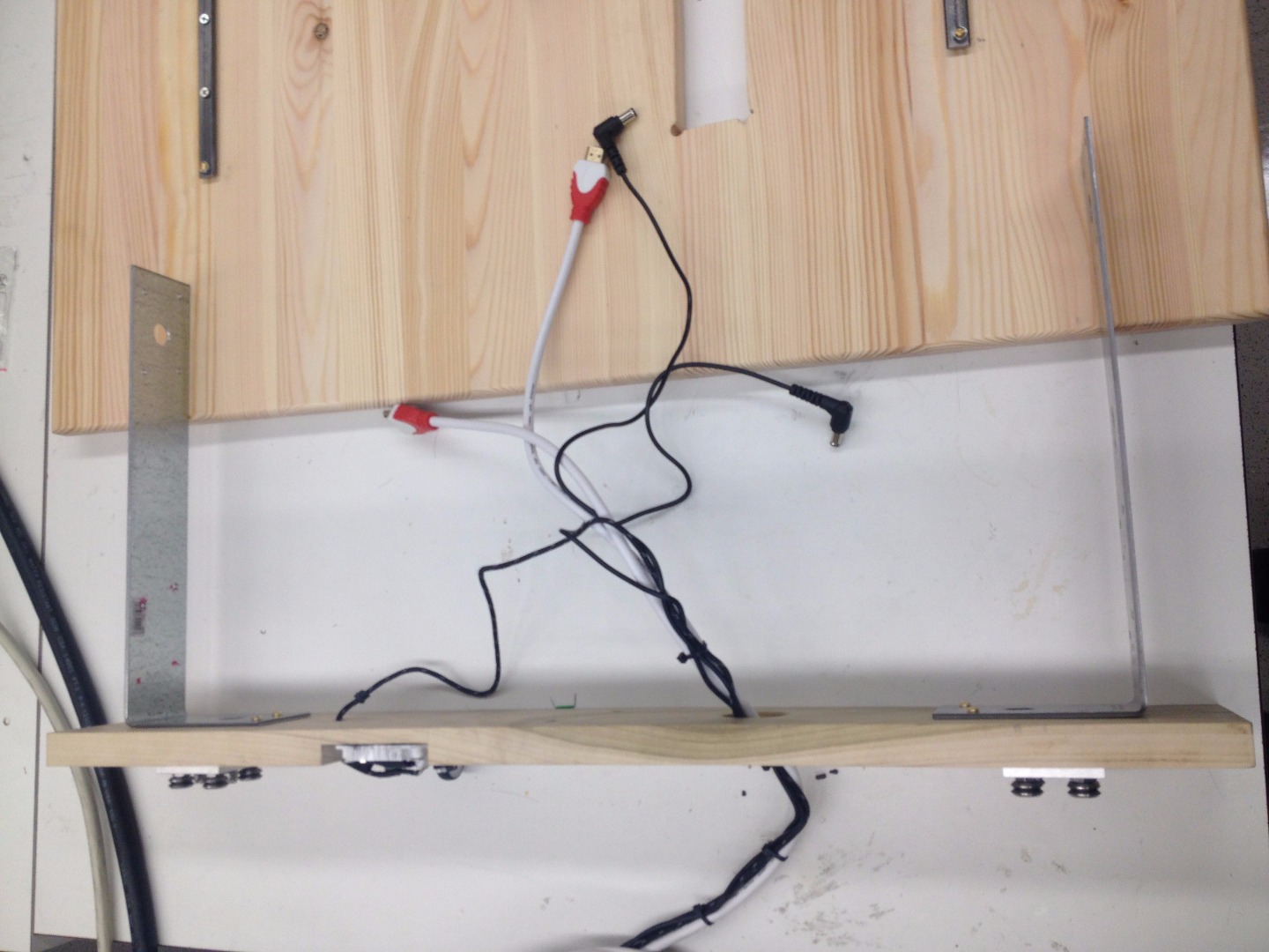
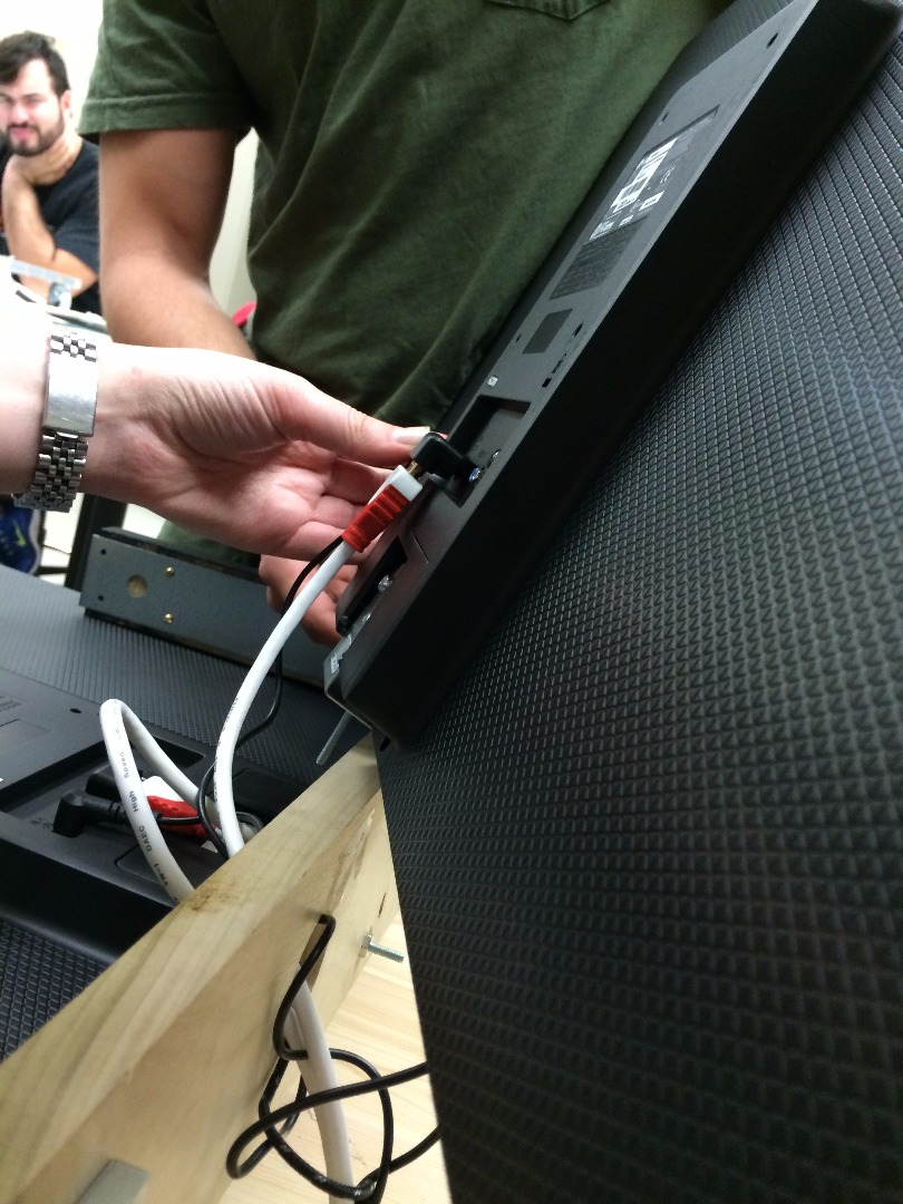
Modify the Brackets
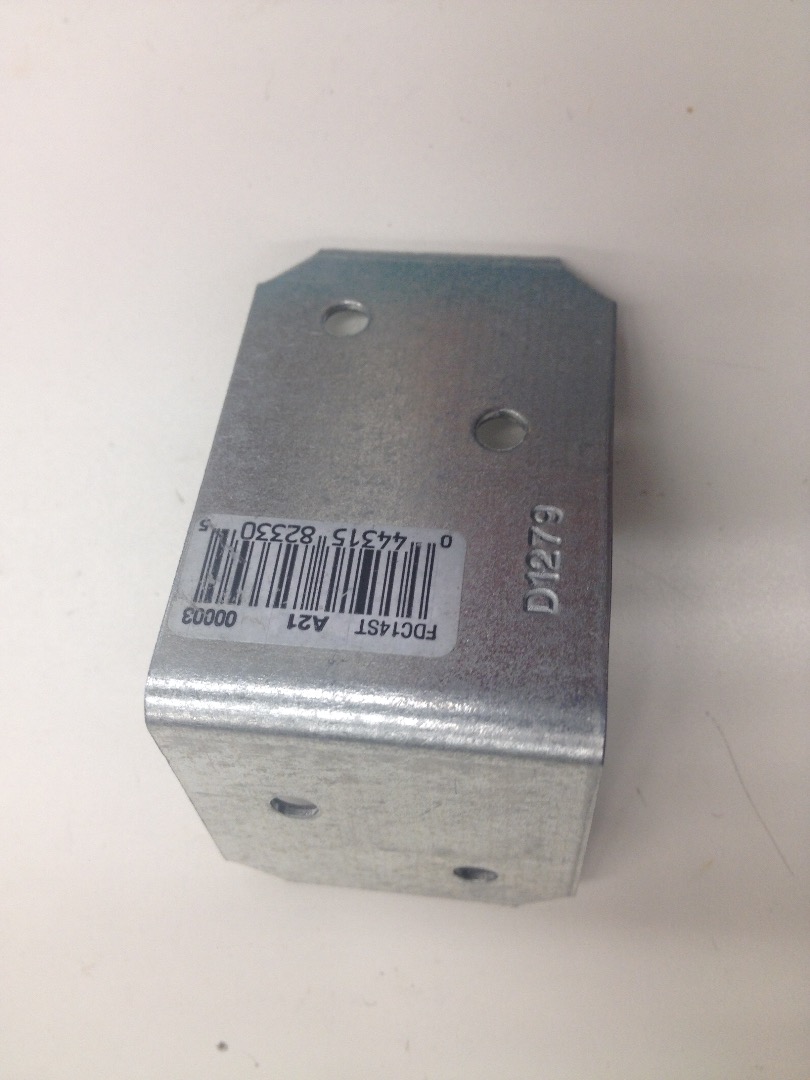
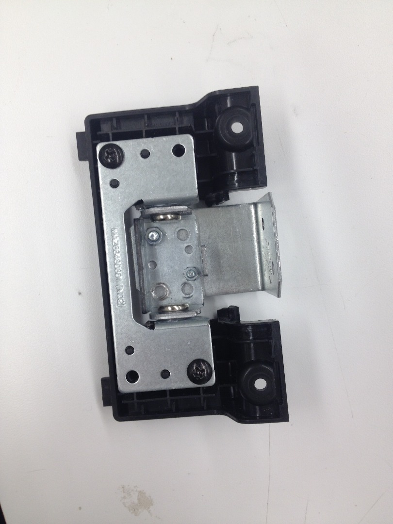
This step is a little tricky. The two monitors come with a mounting bracket on the lower back side of the screens. In order to mount these monitors back to back, you will have to make some adjustments to these brackets.
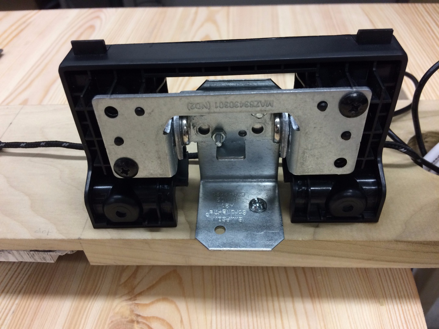
First, remove the metal bracket from its plastic surrounding. You will see that the brackets are capable of rotating, but only within the range determined by the two metal edges. These small edges need to be bent out of place in order to allow the bracket to rotate 180 degrees. We used a hammer to bend the edges out of the way.
Once these edges are no longer obstructing the rotation, you will want to flip the small inner bracket 180 degrees. Then, mount a large L bracket to this piece, with the L facing underneath the mount (where the monitor will be once the mounting piece is reattached).
Mount Monitors
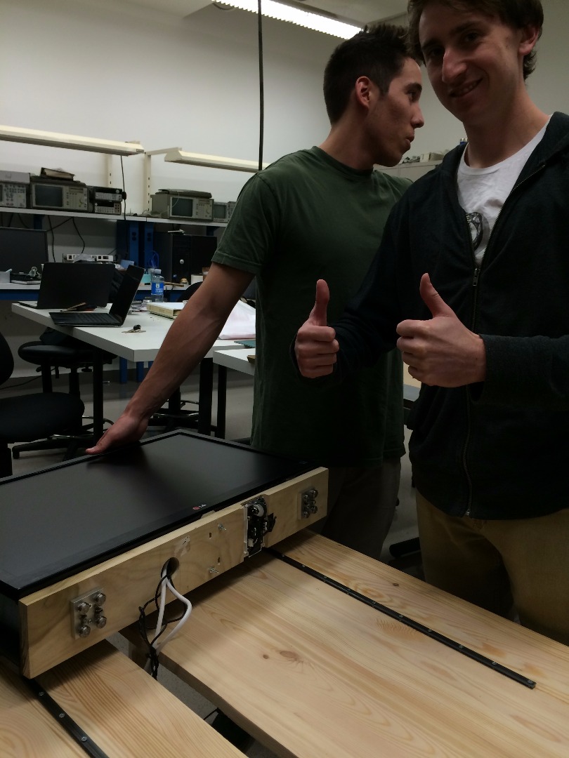
1. Allow room for access to the power button on the bottom of the monitors by offsetting the monitors over the edge of wooden base.
2. Measure where the L-bracket hole will be and drill a hole there on both sides.
3. Attach the monitor brackets with a long screw and washer.
4. Plug in HDMI cables (with 90 degree attachment) and power supply to the monitors, and feed the cords through the holes cut into the base, connecting them to the laptop.
5. Attached the monitors to the monitor brackets.
6. Use zip ties to keep the 4 cables together; approximately one zip tie for every 3 inches of cable
Construct Frame
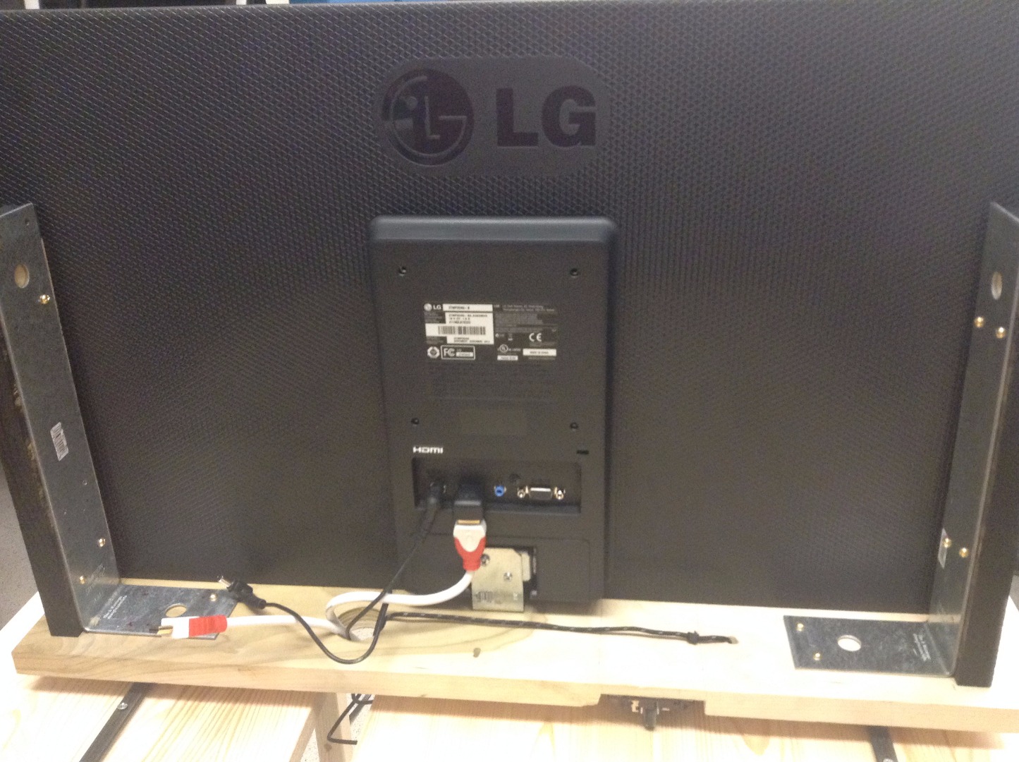
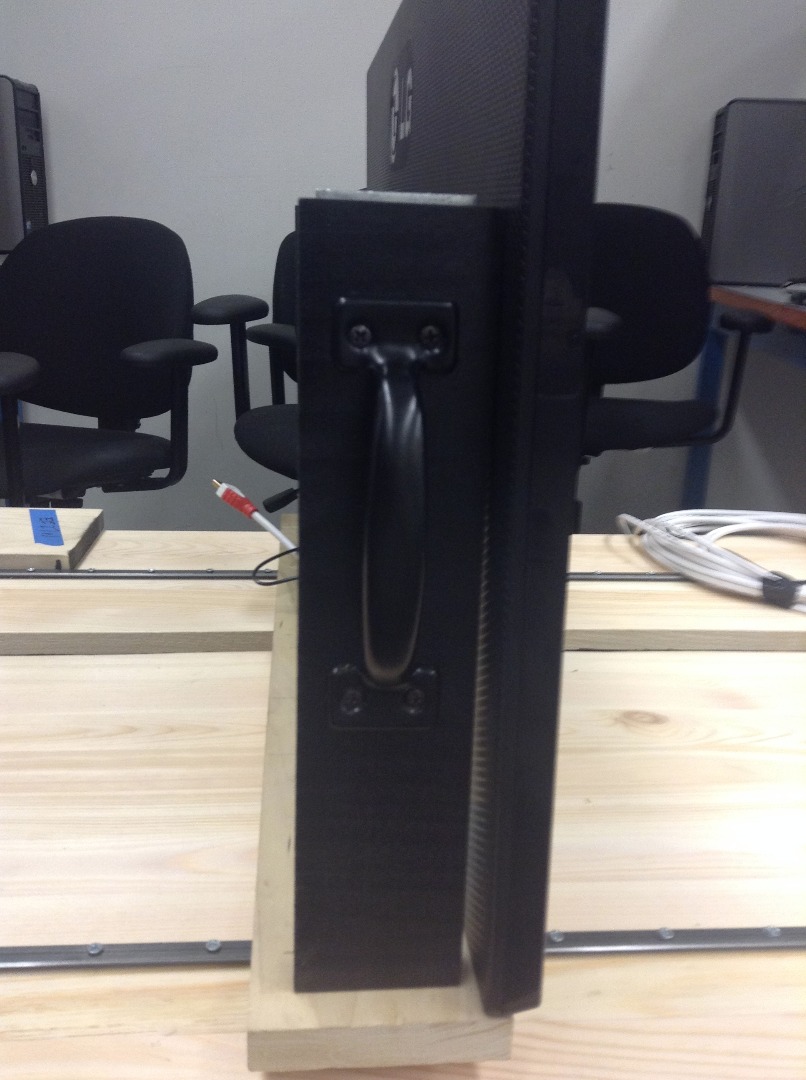
Assemble Frame
We drilled holes in the large L-brackets so that we could attach them with wood screws to our base and to the sides of the frame.
We attached two large L-brackets so that, when wood was attached to them, they were about ½” indented from the monitors. We then attached the wood to the brackets.
For the top of the frame, we attached the three pieces of the frame with L-brackets.
Add Handles
The handles were attached to the inside cover we built. The handles that we used were 5.5" long and 1.5" wide. The handles were attached 4.5" from the top of our wooden cover, 4.25" from the bottom, and ½" from the sides of the monitors (centered).
Uploading Content
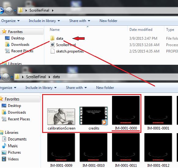
Upload Image Sets
Currently, we have a sample image set loaded in the provided data file (see zipped file in the step "Implement Code"). It is a small amount of images, but will allow the program to run so you can set up the project before you find your own image sets.
For our project, we used a full body cadaver image set from the NIH. This data is available on the NIH Visible Human Project website, but you must send in paperwork in order to retrieve the username and password for the data. The link to this information is below:
http://www.nlm.nih.gov/research/visible/getting_d...
MRI and CT scan data also make great image sequences. Below is a link to free downloadable CT and MRI scans. Sequences with image counts between 500-700 work best without allocating too much RAM. Most MRI and CT scans are in Dicom (.dcm) format. The program OsiriX can be used to convert dcm images to an acceptable format (such as .jpg or .png). The link to this software download is also below. After download and image conversion, images need to be uploaded to the “data” folder and the code needs to be slightly altered depending on the extensions of the images (shown how to below)
https://imaging.nci.nih.gov/ncia/login.jsf
http://www.osirix-viewer.com/Downloads.html
If you have your own image sets (such as a time-lapse or any other array of sequential images) you can use those by uploading all of the images into the “data” folder of the file with names in the form "prefix####.ext" where #### begins at 0000. The code can support around 6 different image sets without the menu screen looking too crowded. (If you want to add more, shrink the menu images.) The Processing language supports images of extensions: .gif, .jpg, .tga, .png. More about how processing handles images can be found at the processing webpage below:
https://processing.org/reference/PImage.html
If you have an image set that is not in this name or file format and you want to convert it, or you need to crop, resize, rename or render in any way, the program ImageJ is great for these tasks. This application was used for our project and is very easy to use. The download for this application is linked below.
http://rsb.info.nih.gov/ij/download.html
After all image rendering, there are a few simple modifications of the code to make sure the sketch will run with the new image set. These modifications are shown in the next steps.
Generate Original Content
Choosing a subject can be difficult; pick one that demonstrates obvious change over time (not just people walking around) and compose your shot to avoid background clutter. You will need to take at least five hundred photos to obtain the best effect. We used a Canon Rebel t5i camera to shoot extremely high quality (1080p HD) photos. We found that shooting photos manually (pressing the shutter button every three seconds or so for human movement) produced an impressive time lapse. However, the process was inefficient and annoying to perform, and we would recommend obtaining an intervalometer, which can set the camera to take pictures automatically and reduces camera shake.
Create Credits Video
The credits video overlayed on each scene after inactivity was created using Windows Movie Maker. To make the most effective use of the transparency overlay, use a black background and white text. Be sure to include credit to any sources for content, such as the NIH.
Software Theory (Code)
This entry is not key to getting the visualizer running, but will help you understand what the code is doing and why. Feel free to skip this step to just get it running. The code uses the java-based programming language Processing and turns the monitors into essentially a slideshow. The screen’s location chooses where we are in the slideshow, and as it moves the images scroll through, similar to stop motion animation.
To contain all of the images we wrote a class ImageSet that encapsulates the data into an easily accessible format. It stores the image’s name, extension, number of images for the set, etc. There’s then a second class Scroller that builds the ImageSet and handles displaying everything. The Scroller class is the important one. Theres a buffer that allows for calibrating on the fly while its running. It works by modifying what position values map to what images. It's important this is here because even without mouse acceleration, fast mouse movements can cause you to drift. Details of its use are in the next step. If you're curious about this check out the code.
Implement Code
First, you will need to download the programming language Processing onto your computer. The link to the download is below.
https://processing.org/download/
To get your own image sets running, find the code:
<p>  //Image set setup<br>  imageSets = new ArrayList<imageset>();
  //*******************************************************************************
  //*******************************************************************************
  //Change these to the prefix, extension, and number of images in your set(s)
  //  remember to place the image files in the data folder
  //Images should be in the form prefix####.ext where #### start at 0000
  //  and ext is one of jpg, gif, png, or tga

  //imageSets.add(new ImageSet("prefix", "ext", #));
  imageSets.add(new ImageSet("Fish", "jpg", 21)); </imageset></p><p>  //*******************************************************************************
  //*******************************************************************************
  credits = new Movie(this, "credits.mp4");</p>
and add your own objects to imageSets following the example. The commented out code shows the form in which these entries should be:
imageSets.add(new ImageSet("prefix", "ext", #)); *prefix is the image name without does not include last set of 4 digits. example: “IM” for the file “IM0694.jpg”
*ext refers to the image extension (jpg, png, gif, or tga)
*The last parameter is the total number of images in the image sequence. This number is important because it is used to load the correct amount of images from the data folder during the loop.
**Make sure the files are inside of the “data” folder in the same directory as the Processing sketch and in the form prefix####.ext where #### begins at 0000. For an example, look at the files of the short time lapse we provided.
**You can also change the credits line to display your own credits
To make sure the image sequence properly fits the screen:
Be sure to change the dimensions of the display variables at the top of the sketch based on monitor pixel dimensions. The code currently reads:
final int SCREEN_WIDTH = 1920;
final int SCREEN_HEIGHT = 1080;
The code has two other major features in addition to the image slider.
1. It requires the user to calibrate the scroll length at the beginning of every use to ensure the user can then scroll through the entirety of the image set.
2. It allows the user to scroll through the image sets available and select the set they wish to view. These functions are included in the code already.
Notes:
Note 1: We ran our device off a MacBook Pro with a 2.3GHz Intel Core i7 processor with 16GB of RAM and NVIDIA GeForce GT 750M 2048MB Graphics.
Note 2: If your processing sketch is running out of memory, go to Preferences and find the Increase Maximum Available Memory field. We found that 10GB was sufficient for 650+ 1080p PNG photos. If you are using smaller screens or smaller photos, less RAM will suffice.
Important: Mouse Acceleration
To accurately move through the slideshow you'll need to disable mouse acceleration. This is a feature most OSs have where mouse speed affects how far you move. You'll need to look up how to disable it on your machine. Here's the link we used (Mac OS X), you may need to search on your own if this doesn't work:
Important: Monitor Setup
This system is designed to be used on a second and third monitor. If you don’t have 3 monitors, change the line
frame.setLocation(displayWidth, 0);
to
frame.setLocation (0,0);
That will place the program's frame on your first window so you can see it.
Downloads
Aesthetic Finishes
Optional: Paint the Upper Frame for the Screens
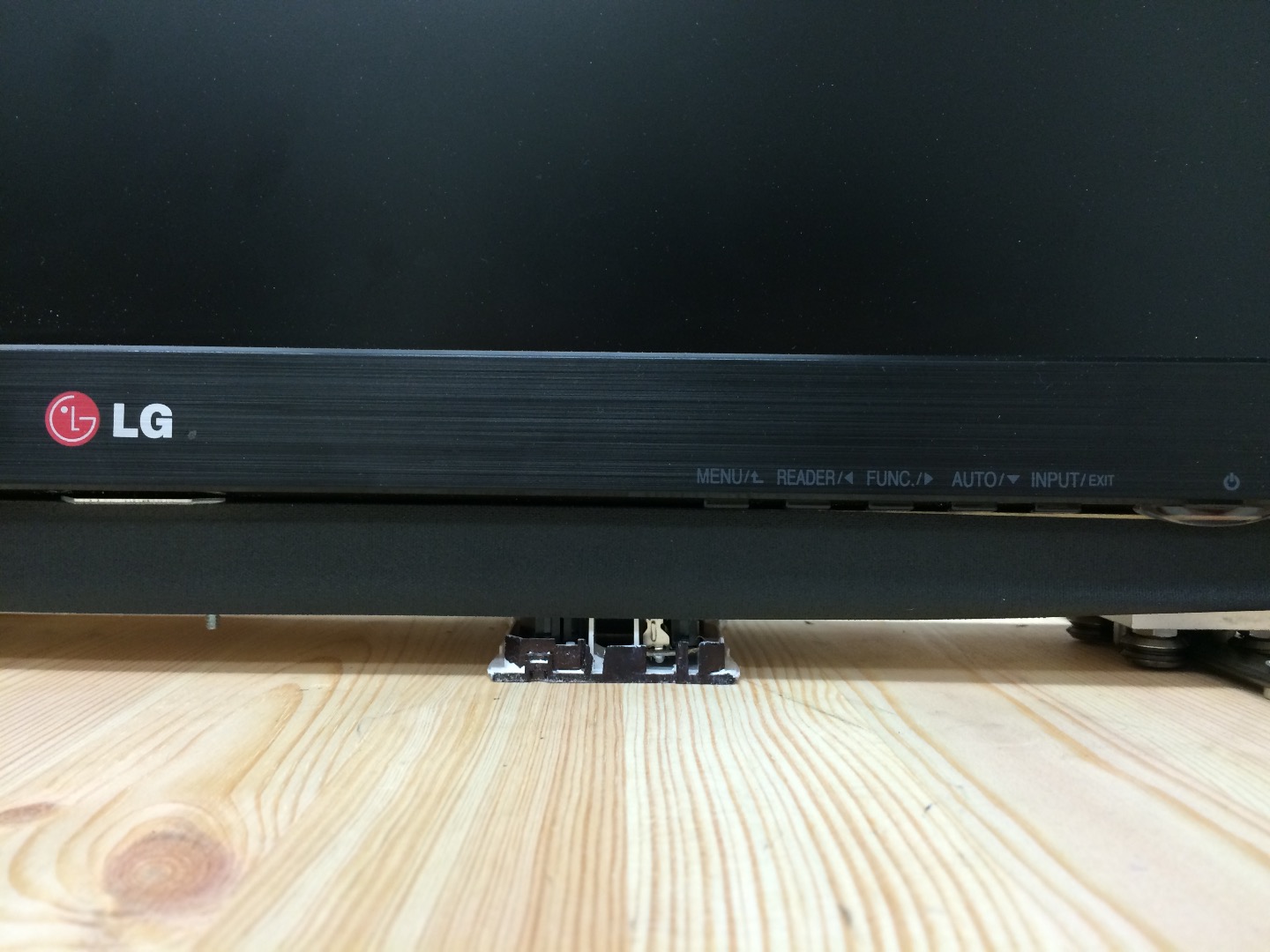
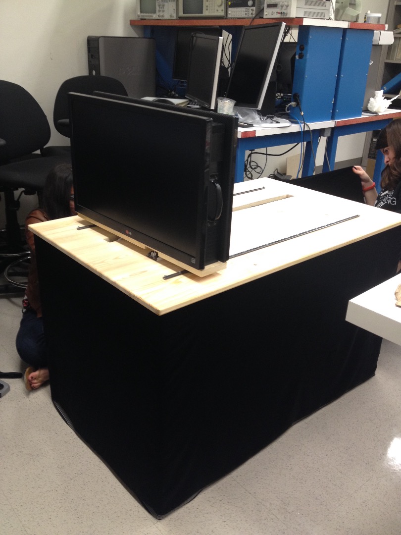
We used a single coat of black spray paint on the upper part of the frame (the three-sided piece that fits on and in between the screens) left to dry overnight (at least twelve hours.) Be sure to put down plenty of paper or a tarp before spray painting the wood frame to prevent accidental spraying of the ground. This is purely an aesthetic design choice (to blend the frame into the screens.)
Sand Down the Wire Slit
We couldn’t make the edges of our slit entirely straight, but we managed to smooth it down considerably to prevent splinters and produce a clean look.
Optional: Staple the Fabric around the Table to Form a Curtain
Since the fabric was longer than the height of the table, we folded it over at the top so it just grazed the ground. Then, using a staple gun, we stapled the doubled fabric up under the lip of the table. (This method allowed us to hide the staples from view.) Starting at one corner, we wrapped the fabric around the legs and lip of the table, with the staples spaced roughly 1.5 feet apart. Once the table was entirely curtained, we cut the fabric, leaving about six inches extra to tuck back under the other end. This will hide the electrical components underneath the table.
Optional: Add Black Tape to Finish the Lower Frame
We found gaffing tape (used for theatre staging) was the perfect width for covering the exposed wood pieces on the bottom edges of the frame, under the screens, and in front of the side pieces of the frame. Be careful to put the tape on slowly and smooth out any bubbles as you stick it on.
Using the Visualizer
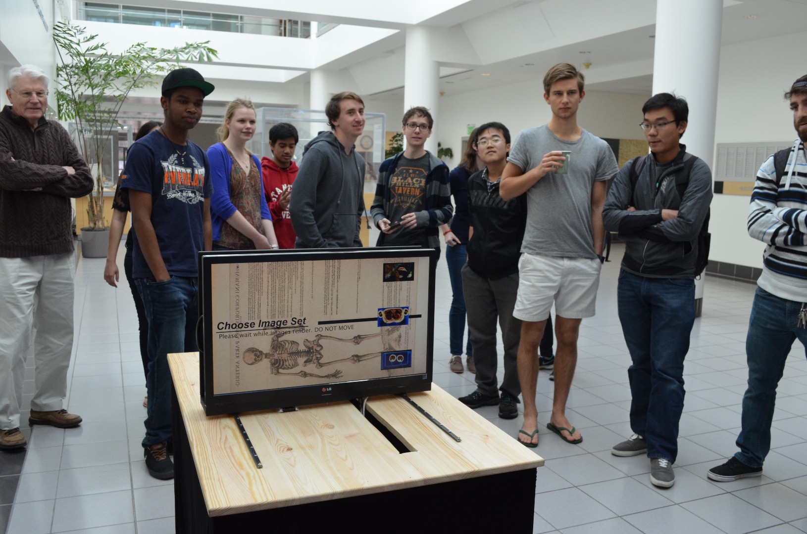
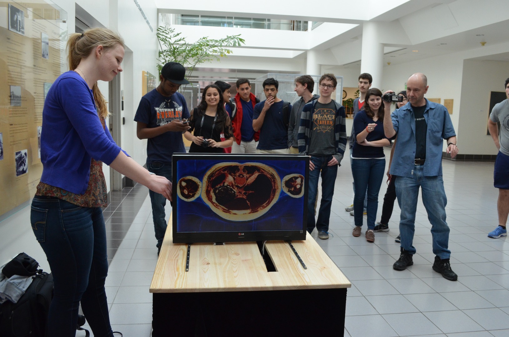
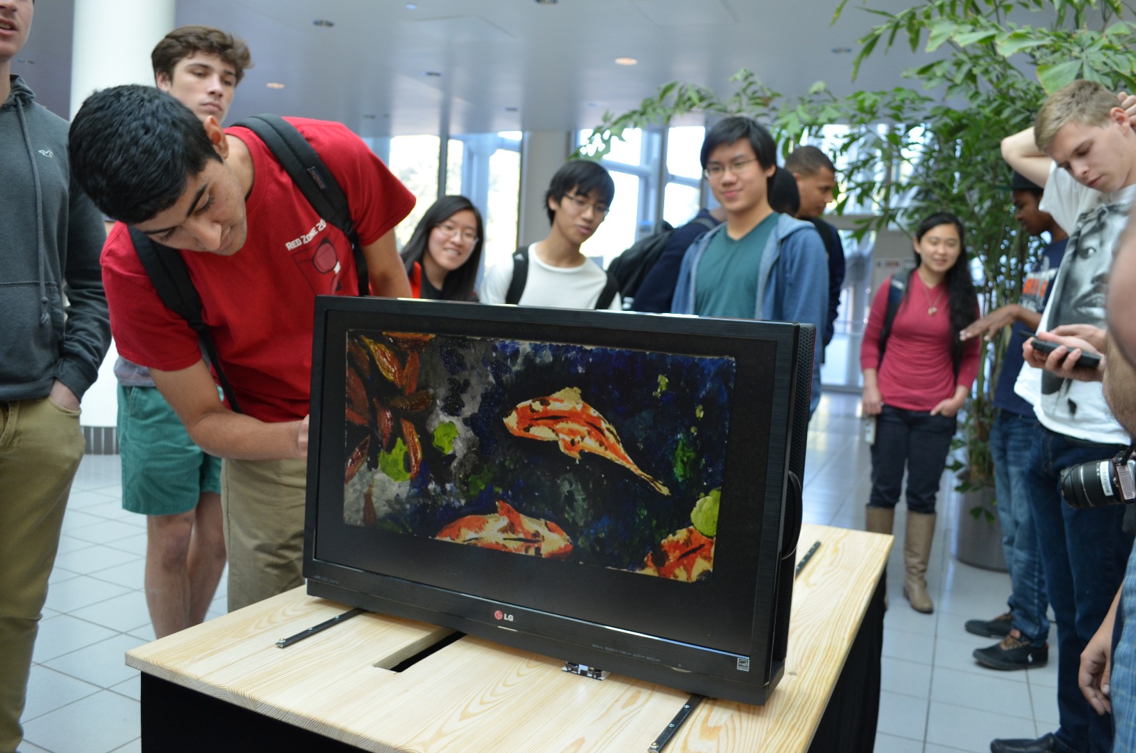
1. Before you execute the program, make sure the scroller is all the way to one end of the track or the other.
2. When you execute the program, a screen will pop up and ask you to calibrate the length of the scroller.
3. Push the Scroller all the way to the other end of the track and hold it in place for 3 seconds in order to calibrate. This gives the program the length of the track, and will distribute the imageset evenly along this length.
4. After calibration, another screen should pop up asking you to select the imageset you wish to view. You can select the image set you wish to view by scrolling the monitors back and forth. You merely need to hover over an imageset to select the one you want to view. A counter will appear and count down the amount of time you need to hover over the image to select it.
5. After selecting the imageset you wish to view, the program will load the image set, which will take a while. Please do not move the slider while the images are loading as it will throw the slider out of sync.
6. After the images load, you will be able to slide back and forth through the imageset. It is possible that the scroller may get out of sync depending on how reliable the mouse sensor is. If this happens, the scroller will stop at the last or first image before reaching the end of the track. If this happens, continue pushing the scroller in the same direction until it reaches the end of the track. This will re-calibrate the Scroller. In order to view a new imageset, you will have to close and reopen the program (and go through the above process from the beginning).
Congratulations! You're ready to display your work to the world.