Arduino + Processing: Interactive Project on LattePanda
by 375668457 in Design > Software
6402 Views, 18 Favorites, 0 Comments
Arduino + Processing: Interactive Project on LattePanda
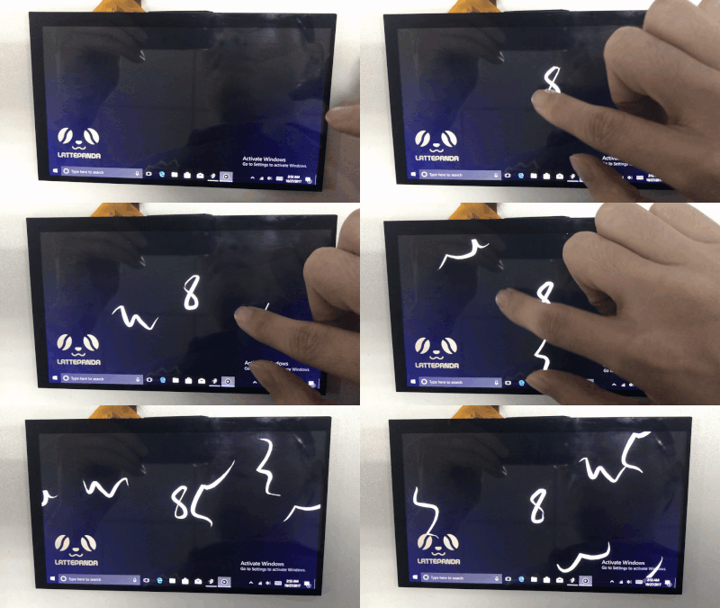
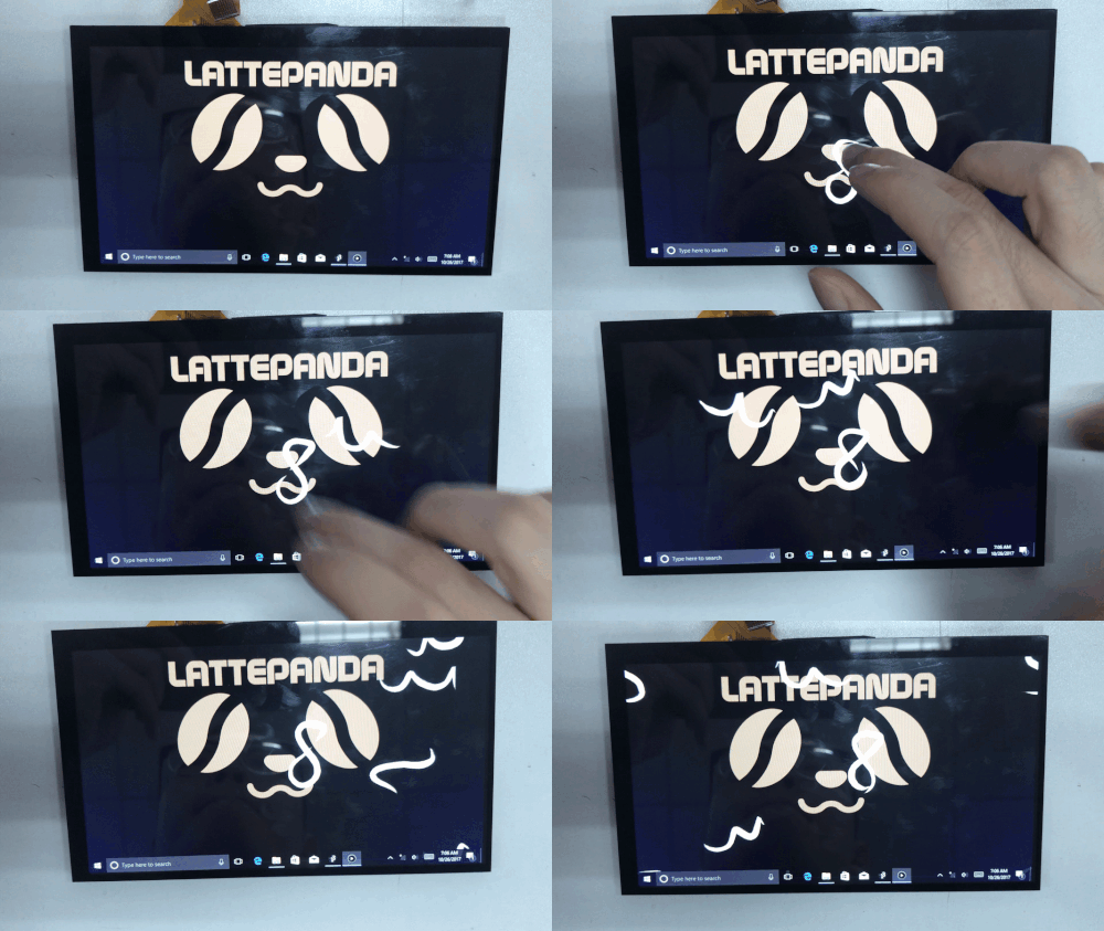
I found a nice Visual Art software called 'Processing'. These days, I'm trying to work on it and run a simple demo on my LattePanda. This $89 single board computer can easily handle this software! More importantly, I can plug in some sensors to make the project much more funny.
This tutorial will tell you how to connect the Arduino to the Processing IDE so they can communicate with one another.
LattePanda is a Win10 single board computer, it also integrated Arduino Compatible Processor, so you can control the physical world easily. If you don't have it, you can connect the Arduino to your PC instead!
Hardware
Software
Hardware Setup
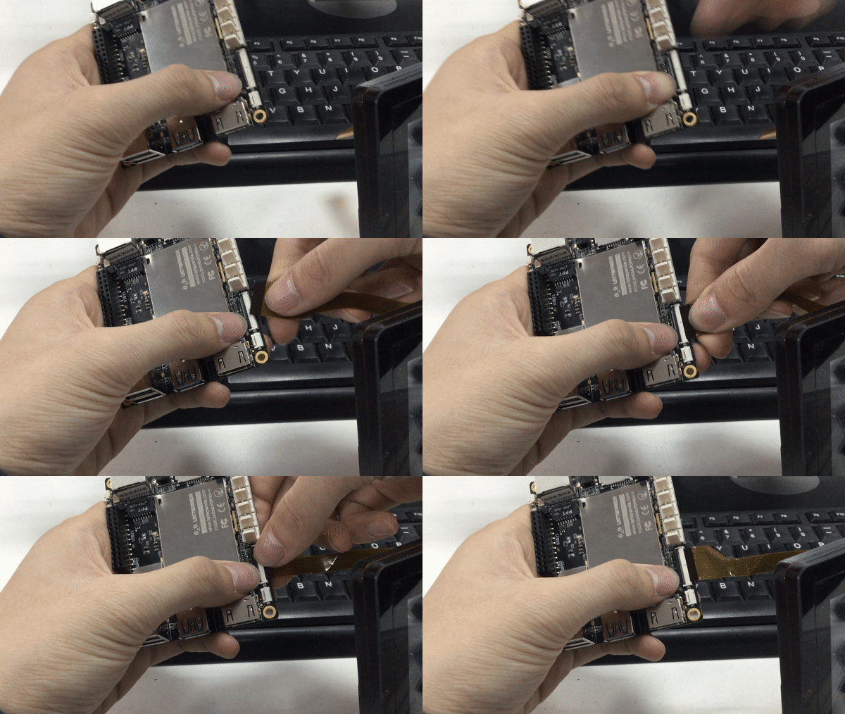
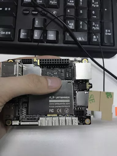
Ensure the board is powered off, and then connect the 7-inch 1024 x 600 IPS Display and LattePanda 7-inch Capacitive Touch Panel Overlay for Display to the LattePanda via the integrated DSI connector.
1. Lift up the actuator
2. Insert the display's FPC cable with the contacts faced downward
3. Secure the actuator
You now have a visual interface for your LattePanda that is powered directly from the board!
Next, connect to Wi-Fi:
1. Connect the Wi-Fi antenna by plugging the round shaped end into the socket labelled “ANT” located next to the 12 x 2 GPIO pins on the board.
2. In Windows select a Wi-Fi connection by clicking the Wi-Fi icon in the system tray at the bottom right of the screen. Follow the wizard to setup a connection. As it's using the Windows interface, you are likely familiar with this process already.
Next, power on your LattePanda
1. When plugged in, you should see the red LED indicator lights up on the underside of the board. Wait patiently for a few seconds until the LED goes out.
2. When the LED turns off, press and hold the power button for one second to turn the LattePanda on.
Now, the computer is running!
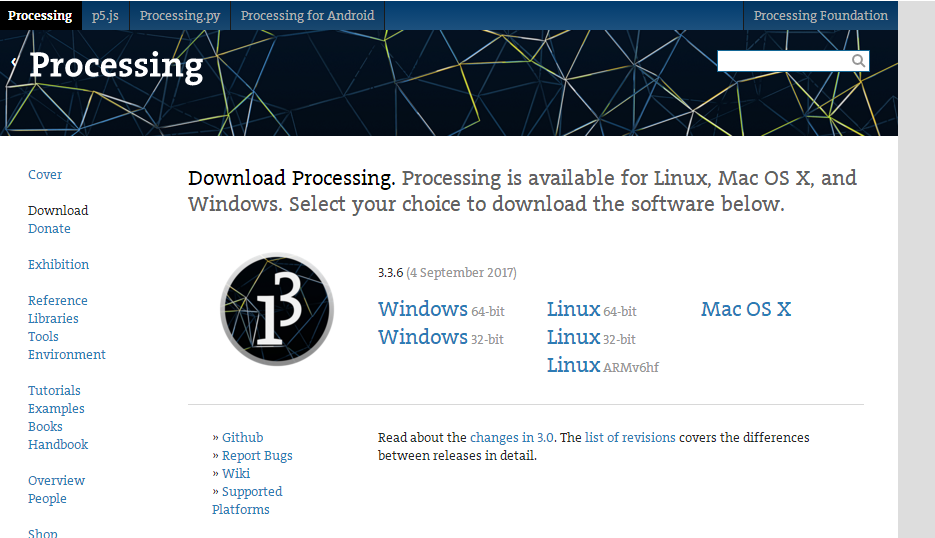
Install Processing
5F.png)
Here's the link.
Inputs and Outputs
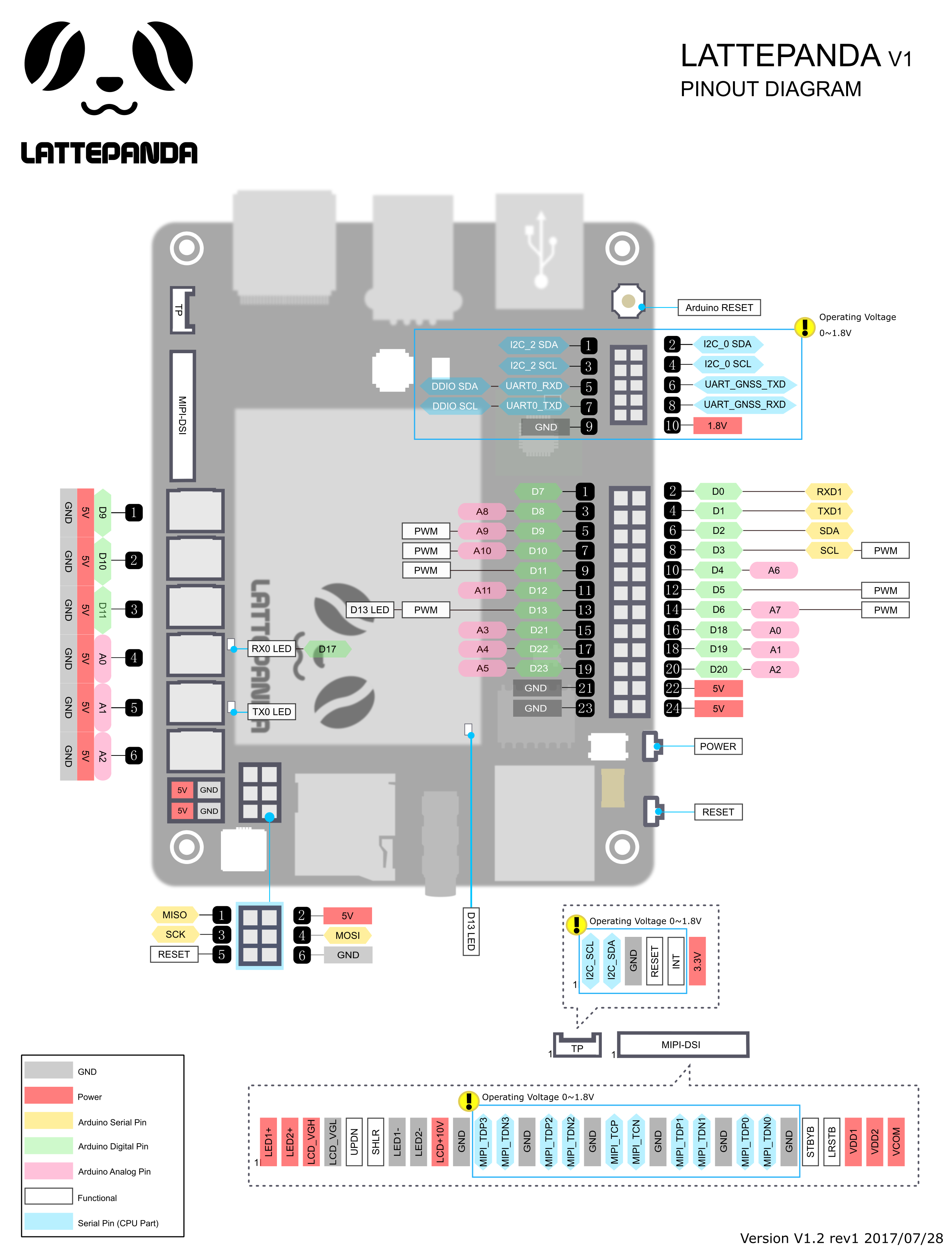
Here is a basic diagram that displays all the pins:
Yellowtail Demo
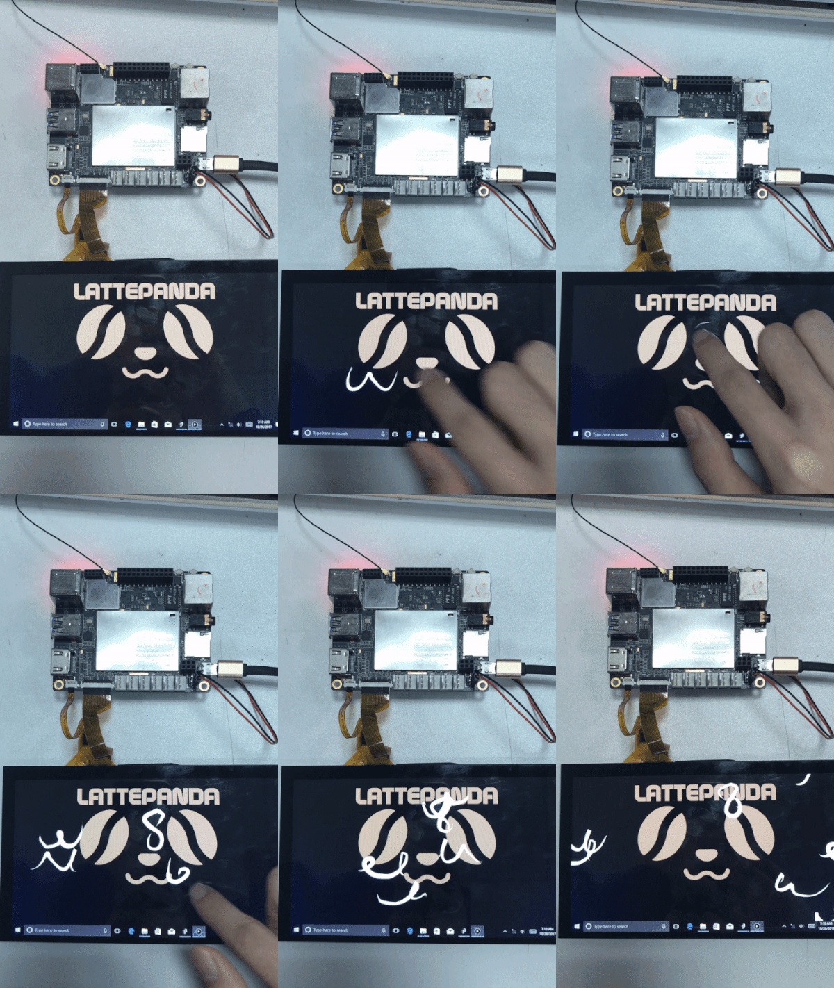
I've upload the source code and you can have a try. It will repeats your strokes end-over-end. Making the best use of the screen and touch panel, It is very cool.
Downloads
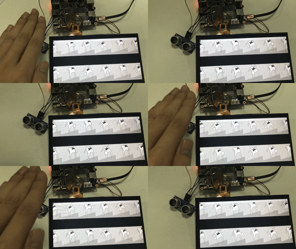
Animation Control Demo(Ultrasonic Sensor)
ayz457n05wm085w_fBanucViR8.png)
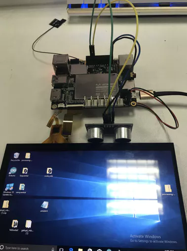
In this demo, you will use a ultrasonic sensor to control the animation. So you need to upload the code to your Arduino and Processing.
The closer you approach to the sensor, the slower the animation will be.
Circuit connection
- Trig —> Digital Pin 2
- Echo —> Digital Pin 3
Arduino sketch:
<p>const int TrigPin = 2;  <br>const int EchoPin = 3;
int cm;
void setup(){
Serial.begin(9600);
pinMode(TrigPin, OUTPUT);
pinMode(EchoPin, INPUT);
}
void loop(){
 digitalWrite(TrigPin, LOW);
delayMicroseconds(2);
digitalWrite(TrigPin, HIGH);
delayMicroseconds(10);
digitalWrite(TrigPin, LOW);
cm = pulseIn(EchoPin, HIGH) / 58.0;
Serial.write(cm);
delay(100);
}</p>
Processing code:
<p>import processing.serial.*;
Serial serial;
int sensorValue;
int numFrames = 12;  // The number of frames in the animation
int currentFrame = 0;
PImage[] images = new PImage[numFrames];
void setup() {
 serial=new Serial(this,"COM5",9600);
 size(1080, 600);
 frameRate(24);
 images[0]  = loadImage("PT_anim0000.gif");
 images[1]  = loadImage("PT_anim0001.gif");
 images[2]  = loadImage("PT_anim0002.gif");
 images[3]  = loadImage("PT_anim0003.gif");
 images[4]  = loadImage("PT_anim0004.gif");
 images[5]  = loadImage("PT_anim0005.gif");
 images[6]  = loadImage("PT_anim0006.gif");
 images[7]  = loadImage("PT_anim0007.gif");
 images[8]  = loadImage("PT_anim0008.gif");
 images[9]  = loadImage("PT_anim0009.gif");
 images[10] = loadImage("PT_anim0010.gif");
 images[11] = loadImage("PT_anim0011.gif");
 // If you don't want to load each image separately
 // and you know how many frames you have, you
 // can create the filenames as the program runs.
 // The nf() command does number formatting, which will
 // ensure that the number is (in this case) 4 digits.
 //for (int i = 0; i < numFrames; i++) {
 //  String imageName = "PT_anim" + nf(i, 4) + ".gif";
 //  images[i] = loadImage(imageName);
 //}
}
void draw() {
 background(0);
 if(serial.available()>0)
 {
   sensorValue=serial.read();
 }
 frameRate(sensorValue+1);
 currentFrame = (currentFrame+1) % numFrames;  // Use % to cycle through frames
 int offset = 0;
 for (int x = -100; x < width; x += images[0].width) {
   image(images[(currentFrame+offset) % numFrames], x, -20);
   offset+=2;
   image(images[(currentFrame+offset) % numFrames], x, height/2);
   offset+=2;
 }
}</p>
Downloads
Animation Control Demo( Analog Rotation Potentiometer Sensor )
`XZL}Y3M$E9A7.png)
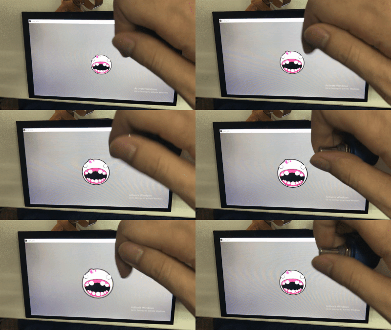
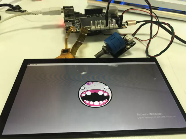
In this demo, you will use an Analog Rotation Potentiometer Sensor to control the Animation. So you need to upload the code to your Arduino and Processing. Rotate the sensor, the size of the baby face will change.
Circuit connection
Rotation Potentiometer Sensor Signal pin —> Analog pin 0
Arduino sketch:
int potPin = 0;
void setup() {
 Serial.begin(9600);
}
void loop() {
 int sensorValue = analogRead(potPin);
 Serial.write(sensorValue/4);
 delay(100);
}
Processing code:
import processing.serial.*;
Serial serial;
int sensorValue;
PShape bot;
void setup() {
 size(640, 360);
   serial=new Serial(this,"COM5",9600);
 // The file "bot1.svg" must be in the data folder
 // of the current sketch to load successfully
 bot = loadShape("bot1.svg");
}
void draw() {
 if(serial.available()>0)
 {
   sensorValue=serial.read();
 }
 background(102);
 translate(width/2, height/2);
 float zoom = map(sensorValue, 0, width, 0.1, 3);
 scale(zoom);
 shape(bot, -140, -140);
}
Downloads
Summary
You can also plug in sensors to make it more funny!
Arduino + Processing is very suitable for the interactive projects!
Enjoy!:->