Interactive Light Art Installation
by edarth21 in Circuits > Arduino
2028 Views, 9 Favorites, 0 Comments
Interactive Light Art Installation
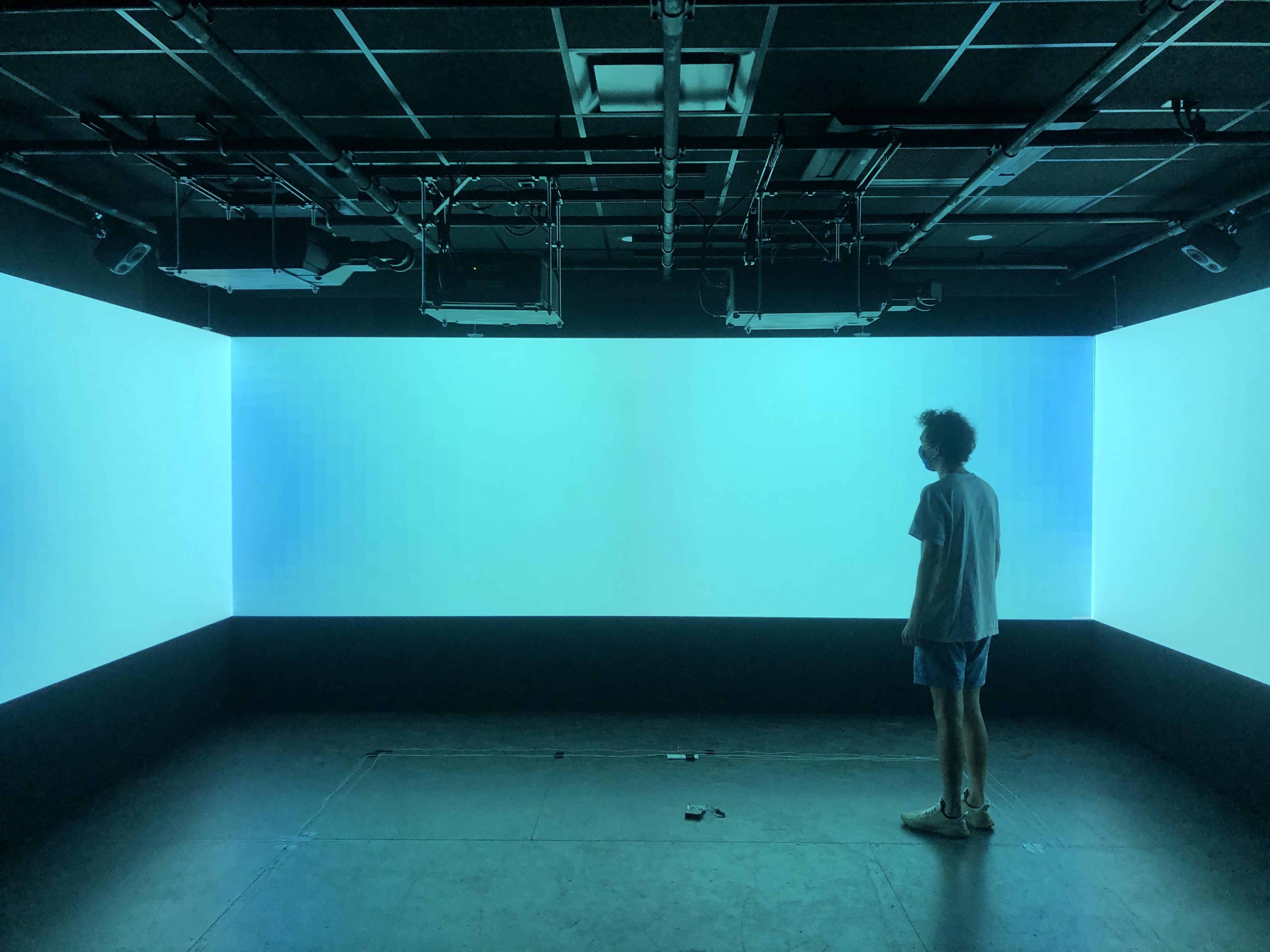
This instructable teaches you how to make an interactive light art installation using Arduino and Unity. Originally designed to be used in an immersive space with a projector array, the system can be built using a normal computer, but the end effect will be rather diluted.
Software Requirements:
- Unity 2021.1.2 https://unity3d.com/get-unity/update
-
Arduino IDE 1.8.13 https://www.arduino.cc/en/software
Supplies
- Arduino Metro Mini https://www.adafruit.com/product/2590
- Adafruit Super-bright 5mm IR LEDs - 940nm https://www.adafruit.com/product/387?gclid=Cj0KCQ...
- IR detectors https://www.sparkfun.com/products/241
- Adafruit Electret Microphone Amplifier - MAX4466 with Adjustable Gain https://www.adafruit.com/product/1063?gclid=Cj0KC...
Circuit Design
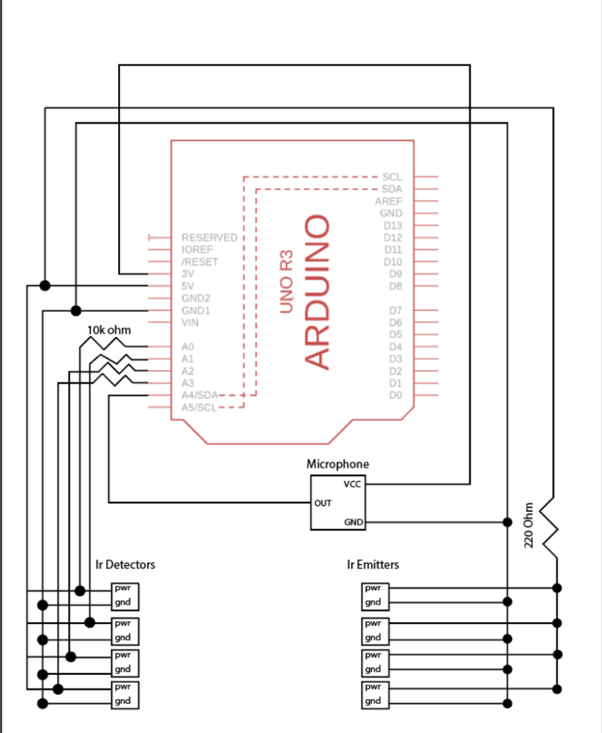
The circuit has two primary components: the IR receivers/microphones and the IR emitters. The IR emitters are connected to their own power supply and placed in their 3d printed housing. The IR receivers and microphone are connected to the computer. Each receiver is connected to an analog input on the metro mini, the 5v power through a resistor, and ground. The microphone is connected to the 5v power, ground, and an analog input. The emitters are connected to the power supply through a resistor and ground. To test that each component is working, simply print the the value received from the analog input of the given component using analogRead() in the loop function. The values printed should changed based off the amount of IR light received by the detectors and amount of noise received by the microphone.
3D Printing
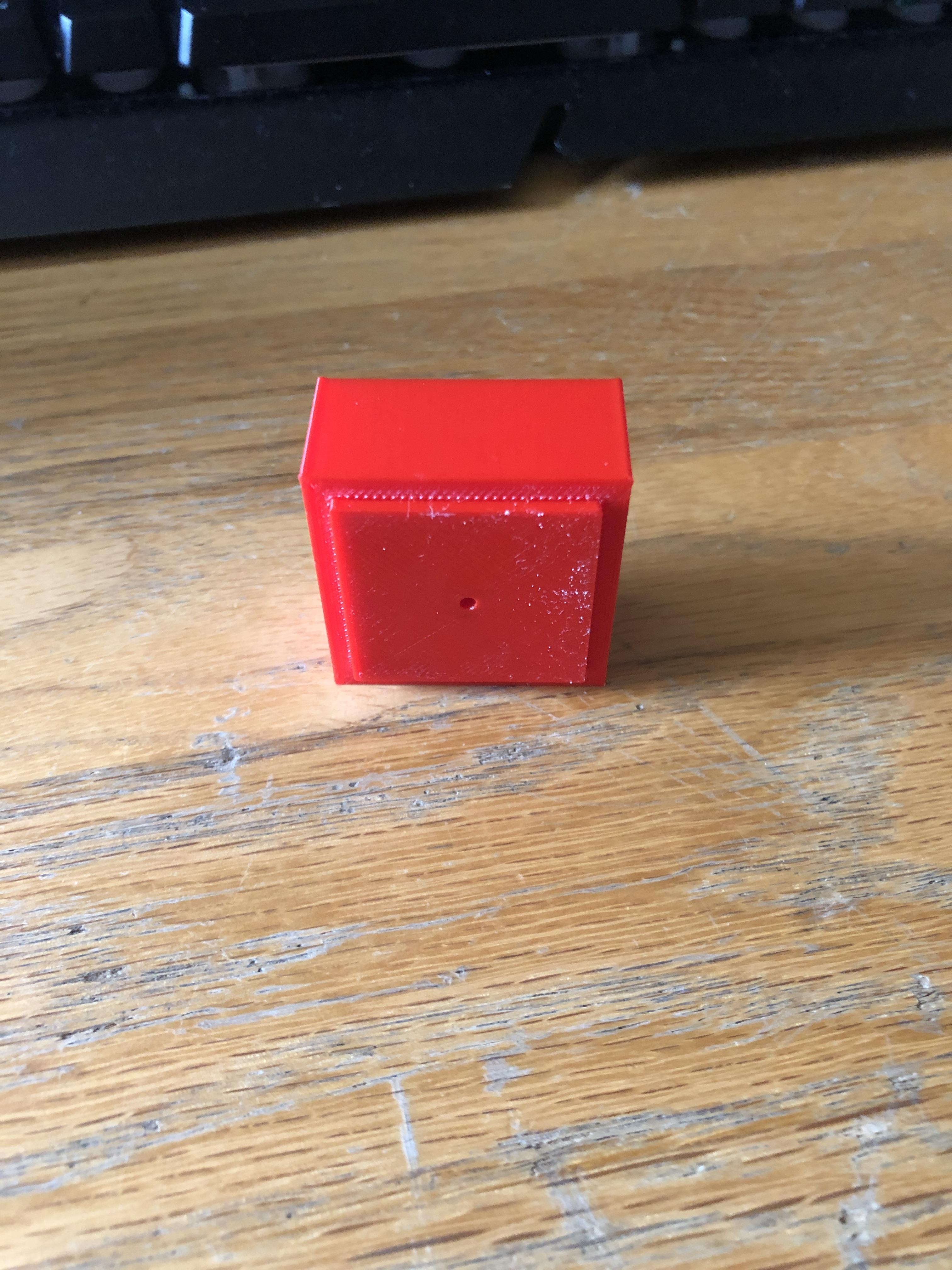
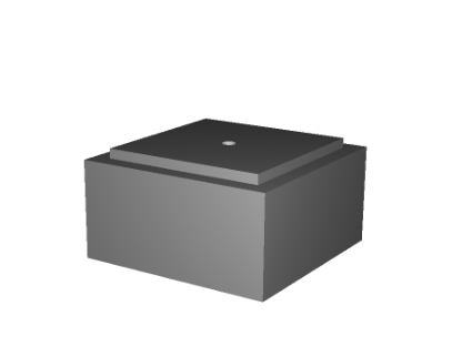
To hold the IR receivers and detectors, I made this simple 3d printed holder. Attached is the stl file so that you can print the holder as well. This was printed using Cura software and an Ultimaker 3d printer.
Downloads
Soldering
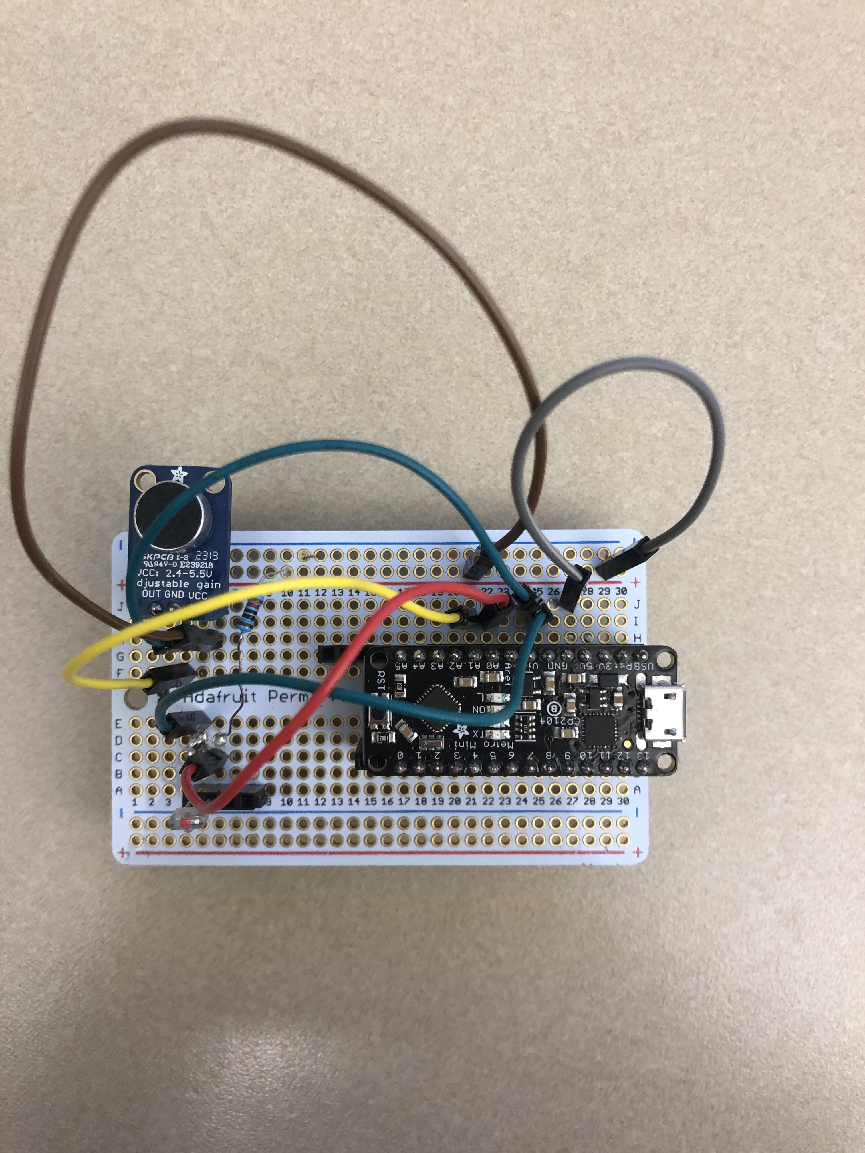
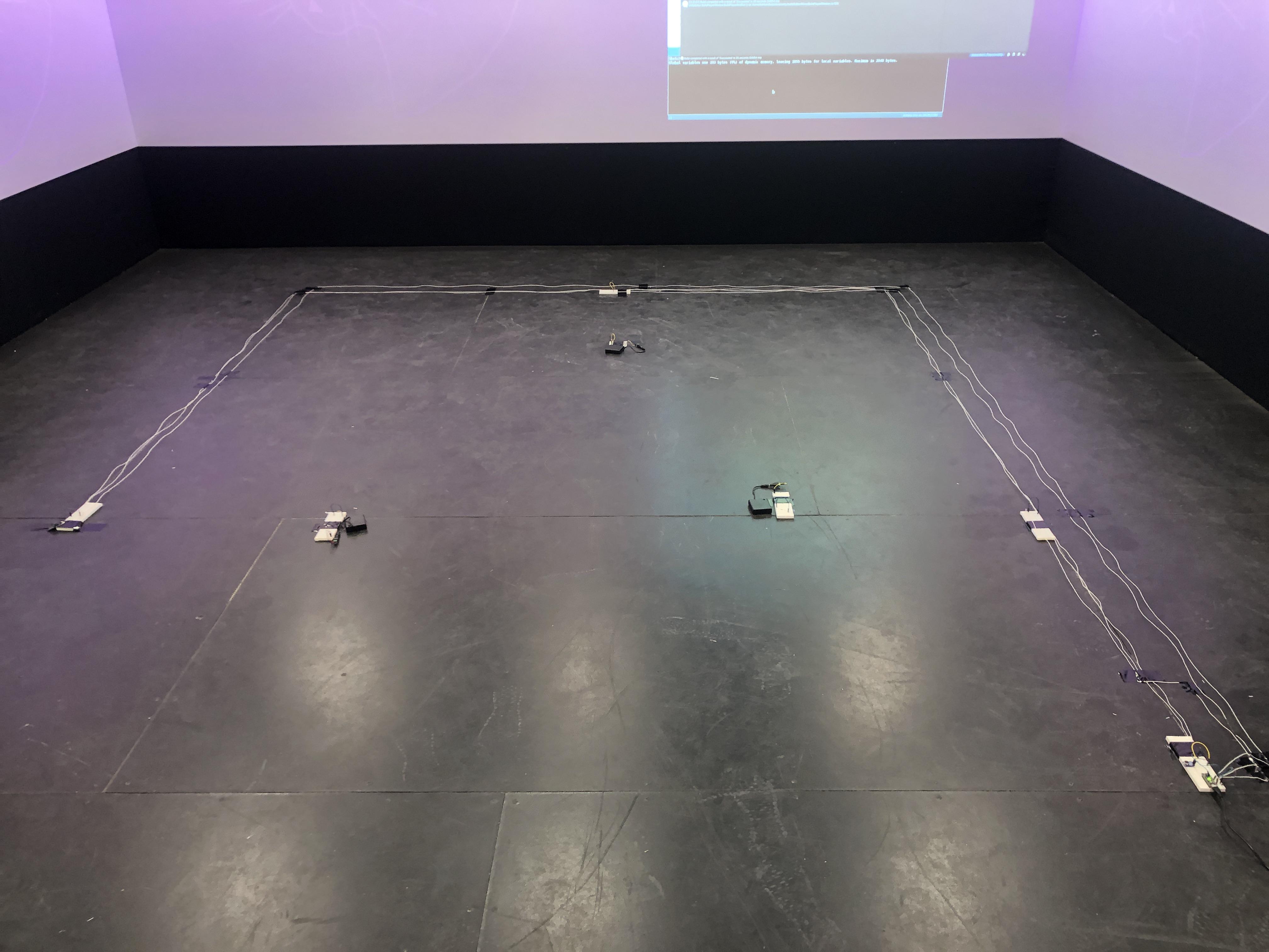
To move from breakout board to prototyping board, solder the metro mini, microphone, and IR receiver to the prototype board. For the emitters, solder the led to a transformer and long wires that can connect to the external battery. To install in the room, place the IR receivers/emitters in parallel and wire to the main Arduino.
Assembly
The bulk of the installation involves creating visualizations in Unity. Using a generic 3d scene in Unity, create an empty object that has a script attached to it. This script controls everything that happens at runtime. The general flow of the script is, when initialized, create an array of cubes that are each assigned their own material. This creates what appears to be a wall in front of the game camera. When the update function is called each frame, the color of each cube is changed based off of its proximity to the origin. The cubes transition between 5 set shades of blue, creating a wave effect. Without any input from the user, the wall will smoothly transition between the colors. Furthermore, when bloom effect is activated on the game camera and the material given to each cube is emissive, the wall has a glow effect with blurs the lines between each cube. Within the same script, a connection to a serial port is opened, allowing for communication between the Arduino and the Unity script. Within in the update function, the script checks if any new communication has been received and uses it to determine what to display. When a user goes through one of the IR pairs, a boolean will be sent from the Arduino code to Unity, flipping a boolean within the script that adjusts the size of the cubes. The end effect is that as the user walks around, the wall appears to dilate and contract. When the user emits a noise above a certain threshold, the speed of the transitions between colors changes, creating a more rushed experience.
Operating Instructions
- connect Arduino to base computer and line up IR emitters and detectors.
- Send Arduino code to microcontroller and turn on IR emitters.
- Run unity code by clicking play button.
- Test walking across IR pairs and making noise.
Potential Improvements
- More color combinations
- Make system react to exact position of users