Interactive Dinosaur Skull
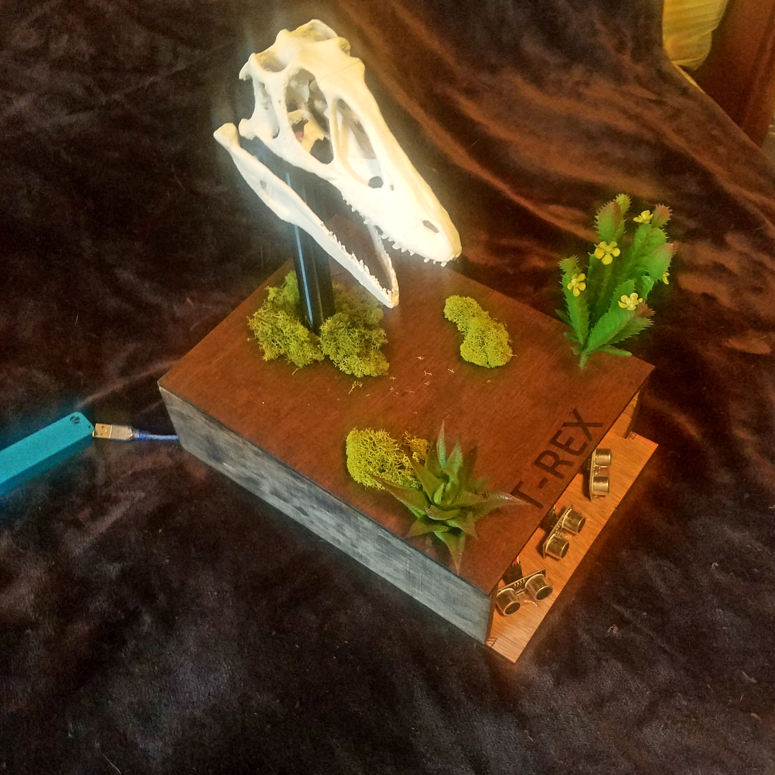
This instructable was created in fulfillment of the project requirement of the Makecourse at the University of South Florida (www.makecourse.com)
3D Printing the Parts
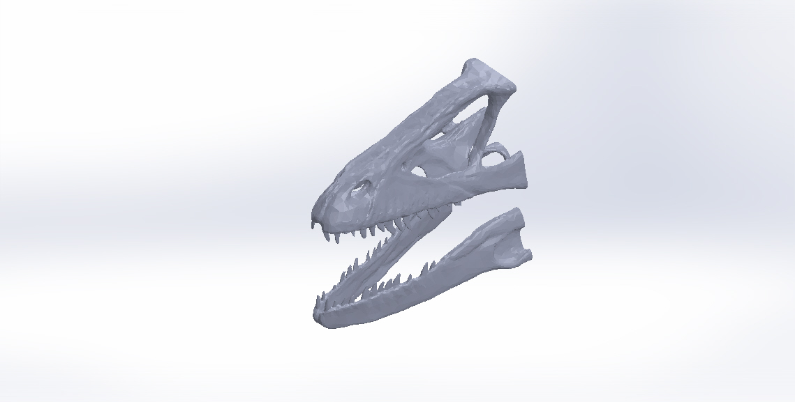
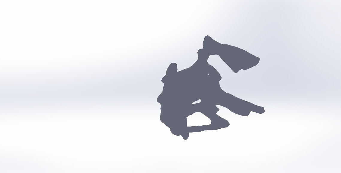
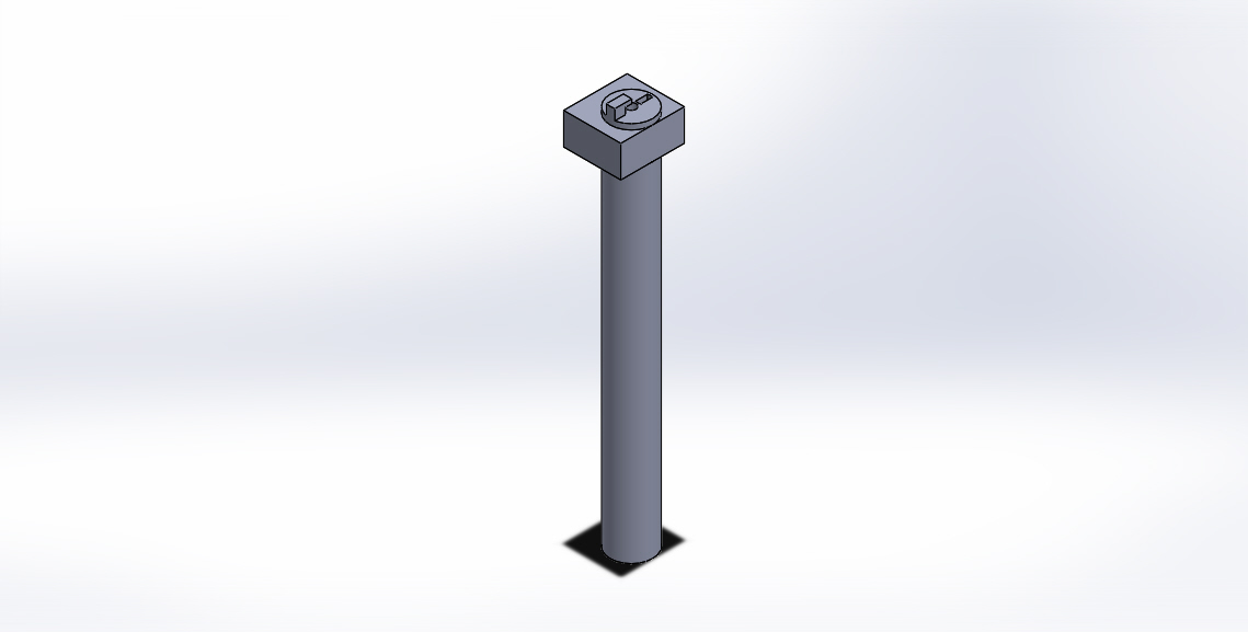
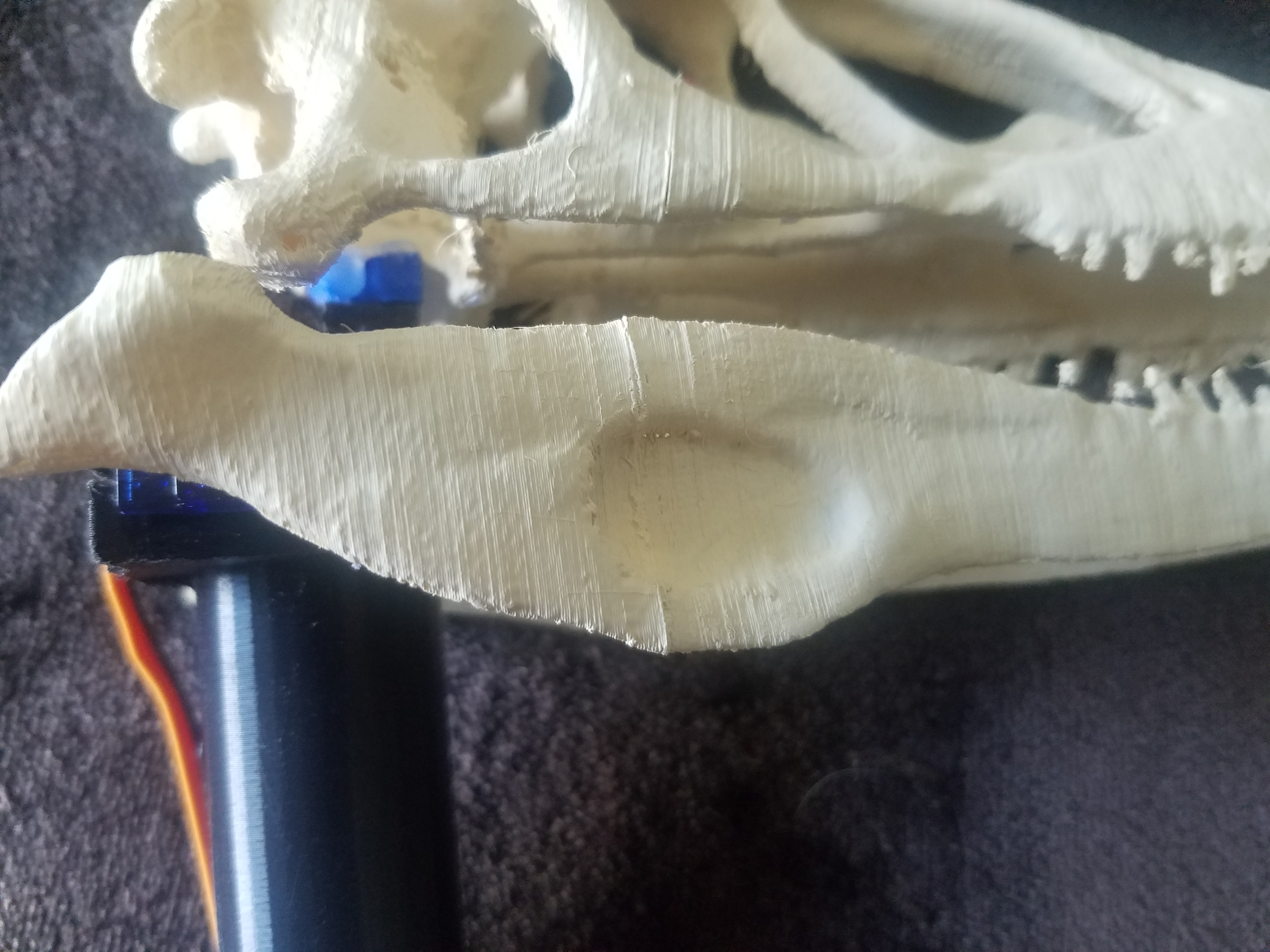
The first step is 3D printing the dinosaur skull and the shaft. I used a pre-designed skull from Thingiverse (located here: https://www.thingiverse.com/thing:14248/files) and designed the shaft myself using Solidworks.
You will need to glue the rear section of the skull (Figure 2 above) to the upper and lower sections (Figure 1 above). The glued sections can be seen in Figure 4.
Creating the Base
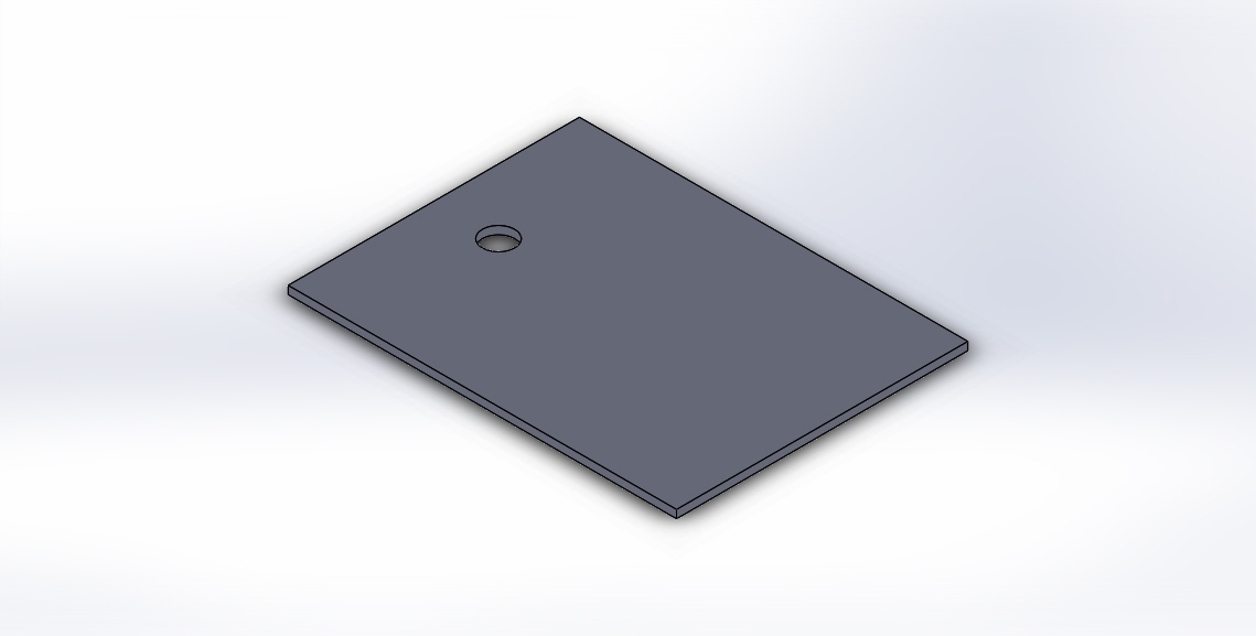
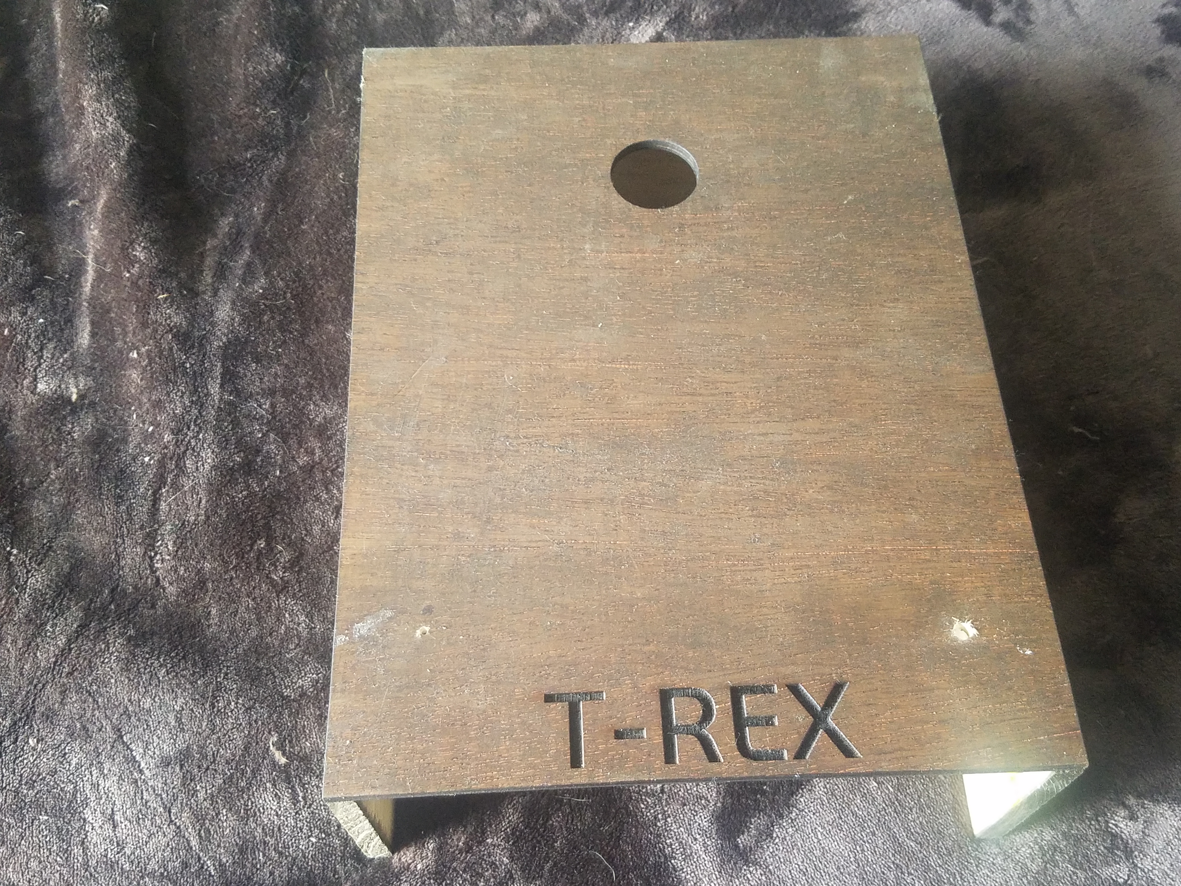
To create the base, I used a Full Spectrum laser cutter to cut out a design I made on Solidworks. Once it was all cut out, I stained the wood and then used wood glue to connect the sides and back pieces as well as rastering the word "T-REX" using the laser cutter (Figure 2 above).
Tip: Do not glue the bottom section until you are ready to place the blackbox to hide the Arduino and breadboard
Connecting the Servo to the Jaw
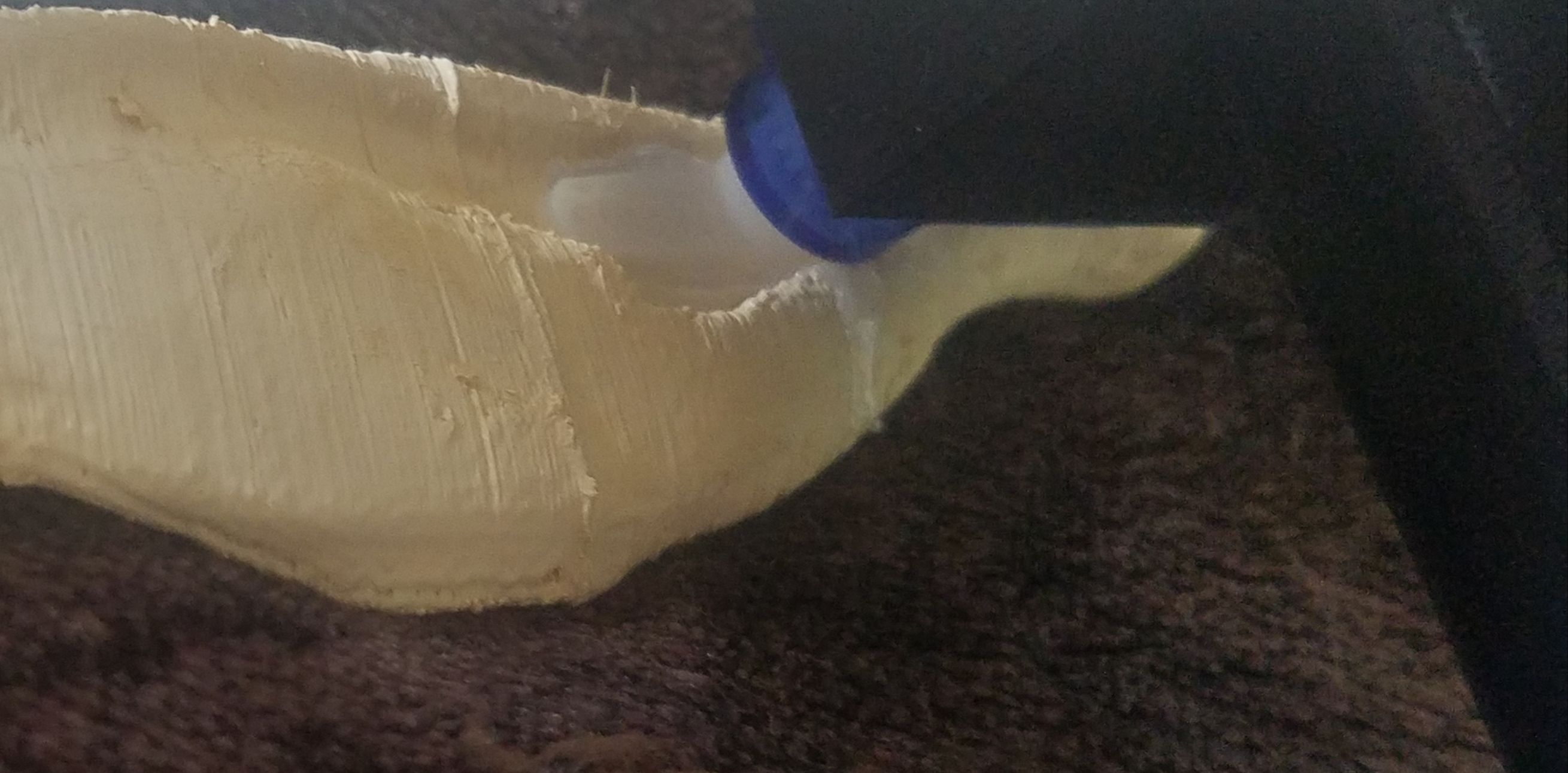
You will need to disconnect (cut) the lower jaw from the upper jaw in this step if you are using the same Thingiverse files, this is necessary for the mouth to be able to open. This is also the time to paint the skull if you wish to do that.
Once this is all done you will need to connect the servo motor to the lower jaw. In the picture listed above, the best way to connect the servo is used the single arm lever and using hot glue to securely attach it to the inside of the jaw (on one side).
NOTE: Ensure the servo is at its 90 degree position prior to gluing it to the jaw or else it will not line up properly.
Attach the Skull to the Shaft
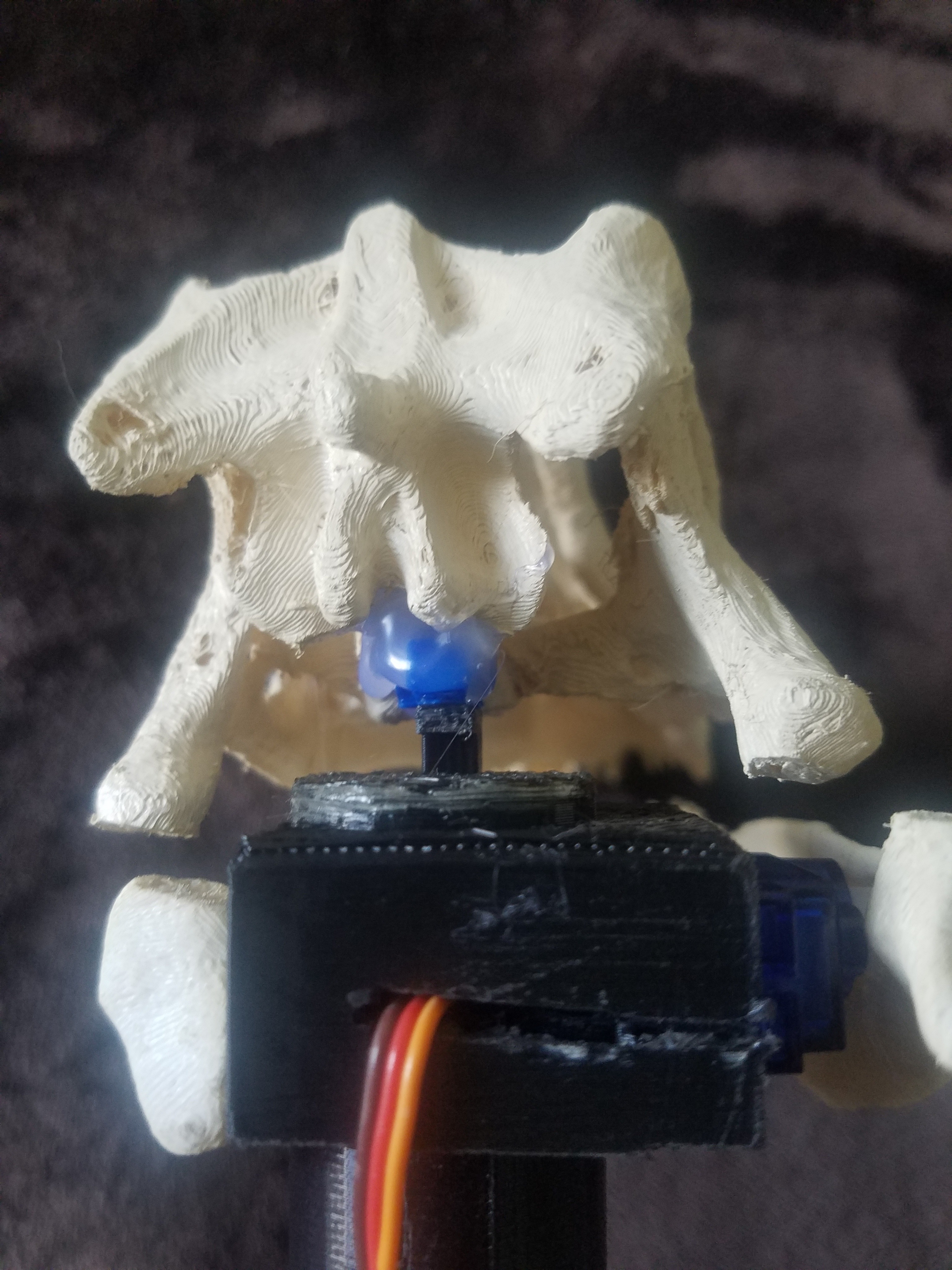
Now is the important step of connecting the top section of the skull tp the shaft. In order to do this, you will have to have the lower jaw (servo included) placed into the shaft. Once the lower jaw is securely in place, you can begin the process of attaching the upper skull.
Since this piece does not ever move it should be secured with a lot of glue. Begin with a dry run of lining up the skull so it is even and level with the lower section and take a mental note of where the skull is resting on the shaft. Then use a hot glue gun and place a liberal amount of hot glue in the skull where the shaft will be attached. Then firmly press the skull onto the shaft and ensure it is lined up with the lower jaw until the glue cools and is set. See the picture above for an example of where I placed the top skull.
Connect the LED Eyes
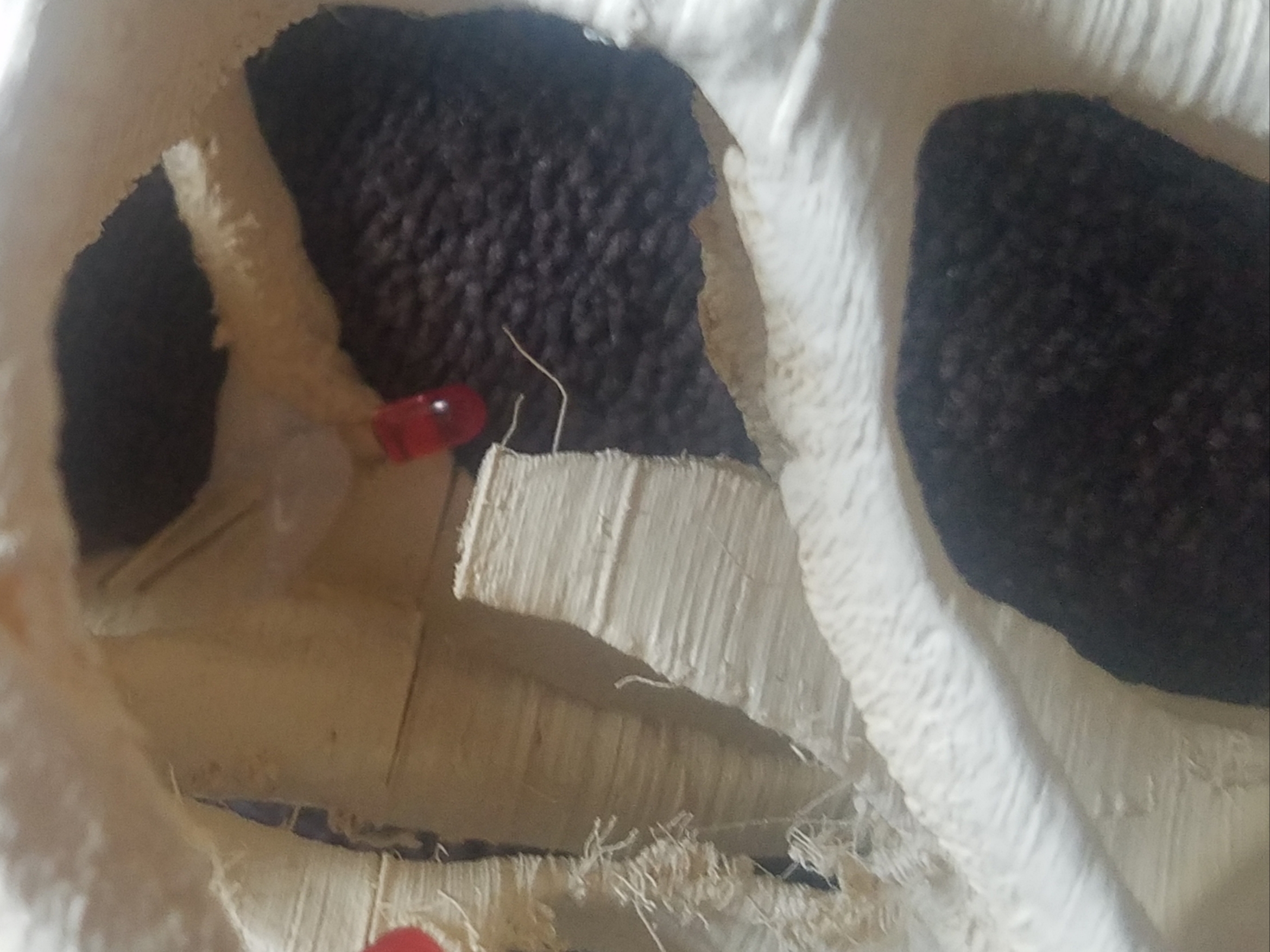
This next step will take precision gluing. Place the LED in the space where it can represent the eye of the dinosaur and apply a small bead of hot glue to the inside of the skull near the middle of the LED wires so you can still connect them to the wiring.
This will be tricky because there is not much room inside the skull for some hot glue guns, take your time and be as precise as possible.
Connect the Shaft to the Servo
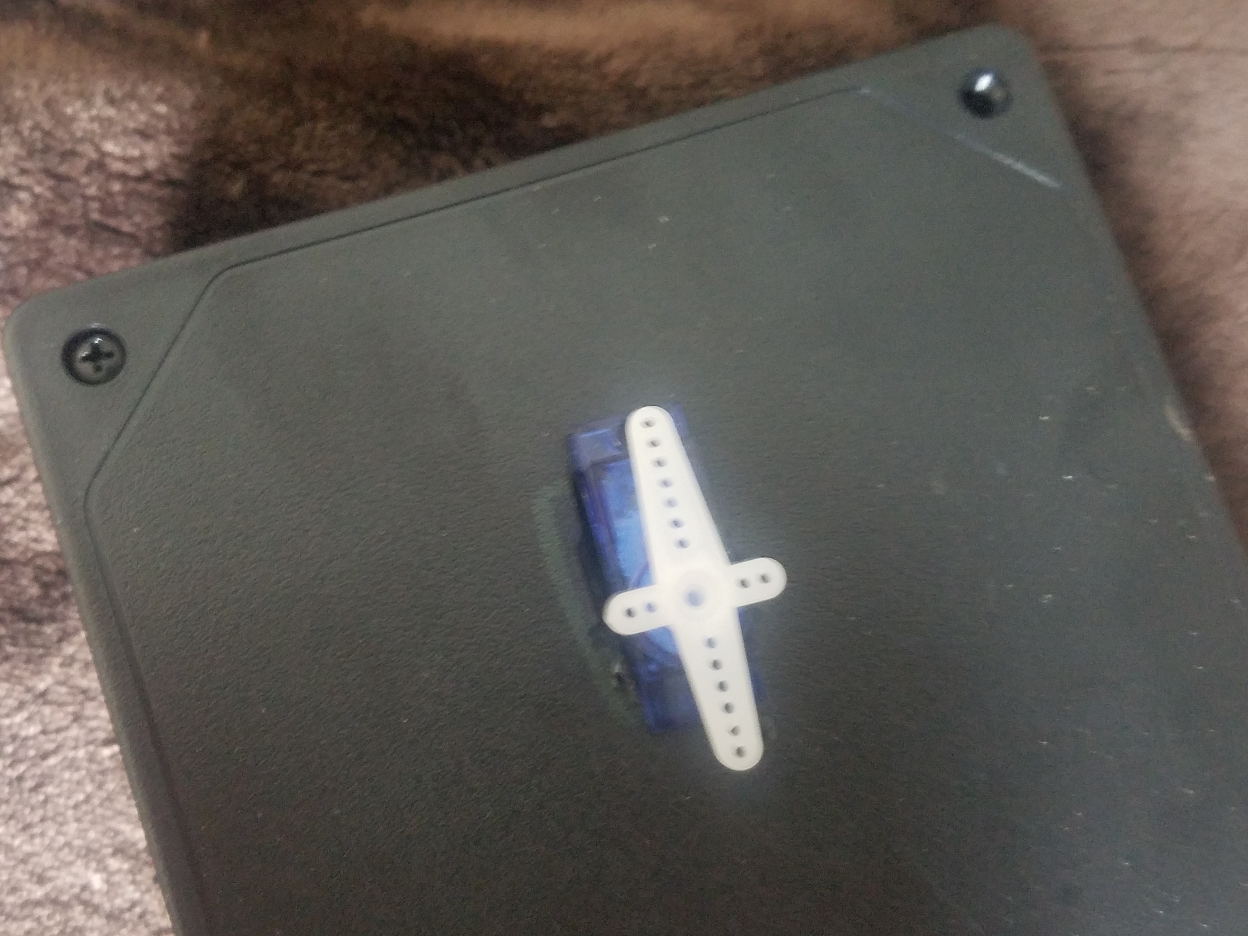
This is one of the last major steps, you're almost there! For this, it is easiest to use the four arm attachment on the servo motor (see above Figure 1) and use a liberal amount of hot glue to connect the four arm servo attachment to the bottom face of the shaft (see above Figure 2).
NOTE: Ensure the motor is at it's 90 degree angle so you can position the shaft with the head aiming forward.
Wire the Circuitry to the Arduino
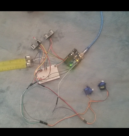
Now that the major construction has been completed, it is time to wire all of the components to the Arduino. You may want to use extra wire attachments to span the distance if the wires provided were not long enough. These can be found for a reasonable price on Amazon.
The LED eyes can be connected to a single digital pin (I used pin 2) but remember to use a 220 resistor to step down the 5V input.
Both of the servo motors can be connected to digital pins as well (I used pins 9 and 10).
The three proximity sensors will need to be attached to the analog pins, these will take up all of them (A0-A5).
Create the Code
Now that everything is wired up and ready to go, the last step is creating the code to bring this ancient king back to life! The following is the code that I used, feel free to make adjustments to your own if you'd like.
Code:
#include //include the I2C library, this one is a standard Arduino package library
#include //this is the Arduino library for the servo motor
#define ledEyes 2 // defining the pin for the led eyes
#define echoPin1 A0 // defines the pin for the echo port of prox sensor
#define triggerPin1 A1 // defines the pin for the trigger port of prox sensor
#define echoPin2 A2
#define triggerPin2 A3
#define echoPin3 A4
#define triggerPin3 A5
#define servoPin1 9 // defines the pin for the servo motor for the base
#define servoPin2 10 // defines the pin for the servo motor in the jaw
Servo myservojaw; //this defines the servo controlling the jaw
Servo myservoshaft; //this defines the servo controlling the shaft
int duration1; // defining integers to be used in later calculations
int duration2;
int duration3;
int a;
int b;
int c;
float distance1; // These will be used by the proximity sensor to determine distance
float distance2;
float distance3;
int pos1; //these will be used to define the position for the servos
int pos2;
void setup() {
Serial.begin (9600); //9600 is the speed in which the arduino is transfering data or information bites per second // serialbegin is to tell the computer you are going to start communicating
myservojaw.attach(servoPin1); //this attaches the servo in the jaw to pin 9
myservoshaft.attach(servoPin2); //this attaches the servo in the shaft to the pin 10
pos1 = 90; // this defines the position of the servo to 90 degrees
pos2 = 90;
myservojaw.write(pos1); //these two lines tell both servo motors to start at 90 degrees
myservoshaft.write(pos2);
pinMode(ledEyes, OUTPUT); // these define what is an output and what is an input
pinMode(echoPin1, INPUT);
pinMode(triggerPin1, OUTPUT);
pinMode(echoPin2, INPUT);
pinMode(triggerPin2, OUTPUT);
pinMode(echoPin3, INPUT);
pinMode(triggerPin3, OUTPUT);
}
void loop() {
digitalWrite(triggerPin1, LOW); //this ensures the speaker is off
delayMicroseconds(10); //this will delay the code to allow for all noise to dissipate before we send out the signal
digitalWrite (triggerPin1, HIGH); //this turns on the speaker in the prox sensor to send the signal to determine distance
delayMicroseconds (10); //1000 Microseconds is a Millisecond
digitalWrite (triggerPin1, LOW); //to make it pulse
duration1 = pulseIn(echoPin1, HIGH); //wait for high, timer on, timer ends on low
distance1 = (duration1 / 2) / 29.1; //29.1 is the conversion factor to convert to centimeters
a = distance1 / 2.54; //2.54 is the conversion factor to turn this into inches
delay(100);
digitalWrite(triggerPin2, LOW); // this is duplicating the above code for the next proximity sensor
delayMicroseconds(10);
digitalWrite (triggerPin2, HIGH); //this turns on the speaker in the prox sensor to send the signal to determine distance
delayMicroseconds (10); //1000 Microseconds is a Millisecond
digitalWrite (triggerPin2, LOW); //to make it pulse
duration2 = pulseIn(echoPin2, HIGH); //wait for high, timer on, timer ends on low
distance2 = (duration2 / 2) / 29.1; //29.1 is the conversion factor to convert to centimeters
b = distance2 / 2.54; //2.54 is the conversion factor to turn this into inches
delay(100);
digitalWrite(triggerPin3, LOW); //finally we will calculate the distance for the last proximity sensor, this information will be used to determine where the servo's need to go
delayMicroseconds(10);
digitalWrite (triggerPin3, HIGH); //this turns on the speaker in the prox sensor to send the signal to determine distance
delayMicroseconds (10); //1000 Microseconds is a Millisecond
digitalWrite (triggerPin3, LOW); //to make it pulse
duration3 = pulseIn(echoPin3, HIGH); //wait for high, timer on, timer ends on low
distance3 = (duration3 / 2) / 29.1; //29.1 is the conversion factor to convert to centimeters
c = distance3 / 2.54; //2.54 is the conversion factor to turn this into inches
delay(100); //now that the distances are being measured by the three proximity sensors, it is time to determine what happens when one is set off, for this we will use if statements
if (a <= 15 && b >= 15 && c>=15) { //this is defining the limit for the dinosaur to be activated, 15in. digitalWrite(ledEyes, HIGH); //this turns the eyes on
pos1 = 45; //these define the angle both servos need to get to, head turns to the left
pos2 = 60; // mouth opens
myservojaw.write(pos2); //these tell the servos to move to the previously defined angle myservoshaft.write(pos1);
delay(2000); //this is how long the dinosaur will stay aimed at the position
pos1 = 90; //these again define the new angle the servos will take to return to its stationary position
pos2 = 90;
myservoshaft.write(pos1); //these tell the servos to return to the stationary angles
myservojaw.write(pos2);
digitalWrite(ledEyes, LOW); // this turns the lights off
}
if (b <= 15 && a >= 15 && c>=15) { //this is defining the limit for the dinosaur to be activated, 15in. digitalWrite(ledEyes, HIGH); //this turns the eyes on
pos1 = 90; //these define the angle both servos need to get to, head stays stationary for the middle sensor
pos2 = 60; //mouth opens
myservojaw.write(pos2); //these tell the servos to move to the previously defined angle myservoshaft.write(pos1);
delay(2000); //this is how long the dinosaur will stay aimed at the position
pos1 = 90; //these again define the new angle the servos will take to return
pos2 = 90;
myservoshaft.write(pos1); //these tell the servos to return to the stationary angles
myservojaw.write(pos2);
digitalWrite(ledEyes, LOW); // this turns the lights off
}
if (c <= 15 && b >= 15 && a>=15) { //this is defining the limit for the dinosaur to be activated, 15in. digitalWrite(ledEyes, HIGH); //this turns the eyes on
pos1 = 135; //these define the angle both servos need to get to, head turns to the right
pos2 = 60; //mouth opens
myservojaw.write(pos2); //these tell the servos to move to the previously defined angle myservoshaft.write(pos1);
delay(2000); //this is how long the dinosaur will stay aimed at the position
pos1 = 90; //these again define the new angle the servos will take to return
pos2 = 90;
myservoshaft.write(pos1); //these tell the servos to return to the stationary angles
myservojaw.write(pos2);
digitalWrite(ledEyes, LOW); // this turns the lights off
}
delay(500);
}
(Optional)
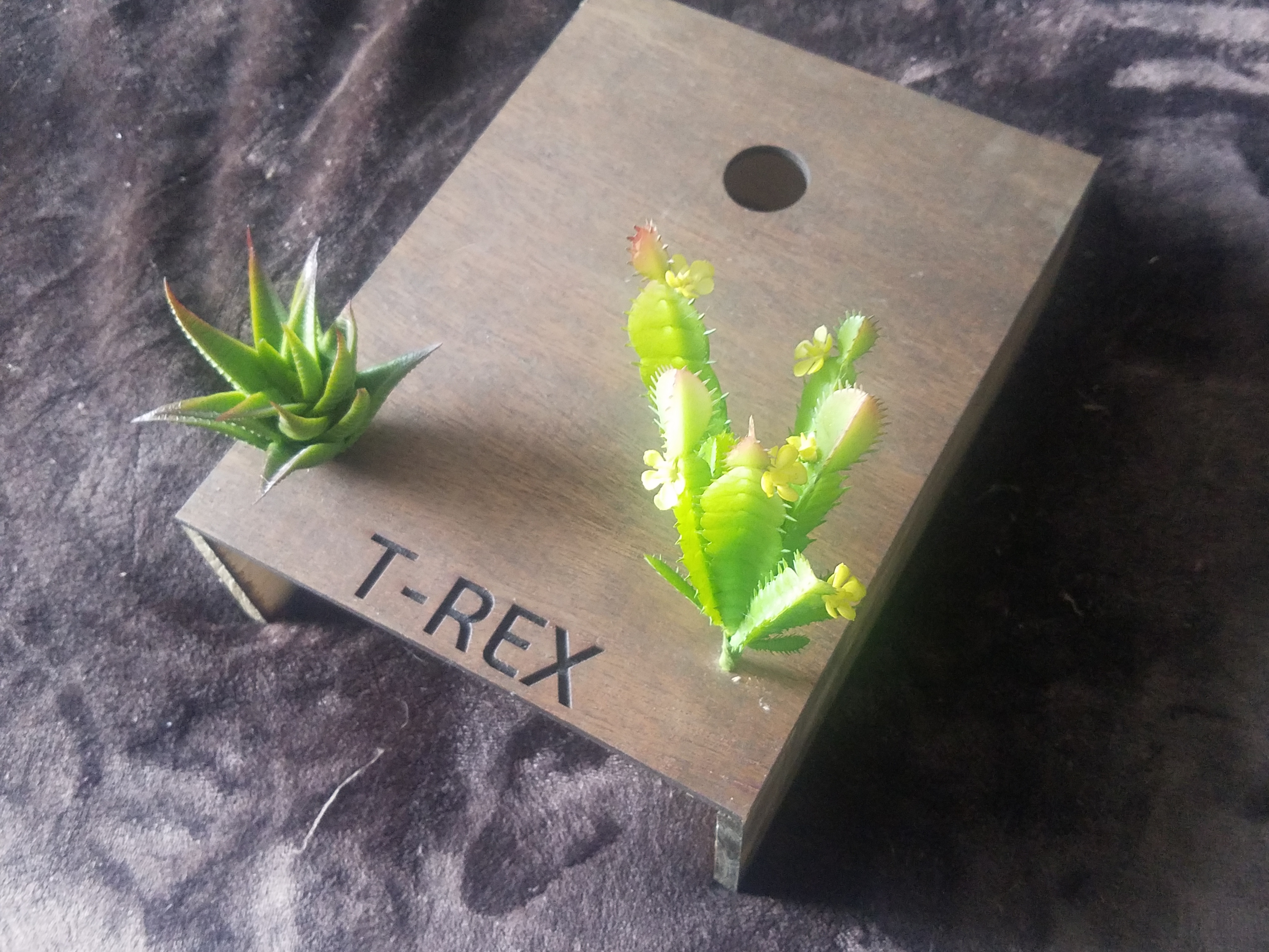
Dress up the setup. I added some decorative small plants and moss to make it look even more awesome, some extra paint can make it look even more realistic as well.
If you want to take it a step further and improve on what I did, design and 3D print a set of eyes for the dinosaur to go over the LEDs.