Intel Edison - Robot
by ThisIsSteve in Circuits > Microcontrollers
9310 Views, 99 Favorites, 0 Comments
Intel Edison - Robot


Quite some time ago I built an Arduino Robot and then upgraded that to a better version which was much faster, after experimenting with the Intel Edison I decided to give the Arduino robot an upgrade and replace the Arduino with the Intel Edison. I made a lot of upgrades added in a better chassis and two more motors and a webcam and made it controlled over the internet. So in this instructable I'm going to show you how to build a robot powered with the Intel Edison board.
This robot can be controlled through WiFi or Bluetooth, can record video and stream it to the internet, it had a higher torque (it can carry heave loads) and has an all terrain chassis.
So lets start building...
Tools and Components


Here is a list of all the tools components required,
Components
- Intel Edison
- L298 Motor Driver
- USB WebCam
- 4 x 300RPM Motors
- Servo
- Li-ion Battery pack
- Micro USB Cable
- Wood
- Wires
- Connectors
- Screws
Tools
- Soldering Iron
- Soldering Wire
- Multimeter
- Pliers
Getting Started


To get started with we need to upgrade the Intel Edison board and Install necessary driver and install the Arduino plugin. I'm running the latest version of Linux on the Intel Edison, I highly recommend you too do so.
The driver requirements are just for windows so if you are using a mac or a Linux OS you can skip this step.
- Download the FTDI drivers.
- Install the drivers make sure you have administrative privileges.
- Download the Intel Edison drivers.
- Also install it.
And now you should have the drivers installed.
Motor Drivers


After you have got your Intel Edison set up ad upgraded to the latest version of the Linux. Next we need a motor controller, as the Intel Edison is capable of handling a 12V motor on its own. For the motor driver we are using a L298 IC, the L298 is a dual motor controller IC and is capable of handling currents up to 5A. The L298 works great with the Intel Edison and if you are looking for a lower powered device you could go for the L293 IC which is similar to the L298 but lower powered.
You can find the circuit board like I have on eBay, or at a local electronics shop.
Wood


To design a robot to be all terrain you need thick and tough wood or you could also go for metal which you may have the risk of short circuiting the board. You need to cut out a rectangular piece of wood make sure the wood is bigger than or just the size of the Intel Edison. You may have noticed that I'm not so good with wood works.
Then you need to screw in the motor clamps at the edges of the wood and make sure they are aligned with each other. If you do this wrong the robot would move in a different direction.
Servo


After you have to wood ready, you need to decide which side of the wood is the front as we need to attach a servo. Leave about 5cm free space from the front of the wood and drill 2 holes both holes just about apart as the with of the servo motor. You may need a low power servo motor as we are running this project from a Li-ion battery, but if you need a higher power source you may need a driver for that too, as the Intel Edison can support a maximum voltage of 5V with the Arduino breakout board.
After you drill the holes you need some hot glue or some double sided tape to hold the servo in place while you can tie the servo on to the wood with the help of some wire ties.
Motors


After you got the servo in place now it is time for the motors, for the motors I used 4 x 300 RPM motors. The L298 is a dual motor controller and you may require 2 of these to drive four motors, but I had to use only one as I connected both the motors of each side in parallel to each other. and then I had only two parallel lines to control. Next we need to mount the motors to the clamp we installed in the previous step. The motors which I used came with a big nut which would help the motors to clamp on to the motor clamps.
Battery


For the battery you could go with a 12V Li-ion battery pack from eBay. I had a few Li-ion Cells from a previous project which I soldered in series to give me about 12V. I used around 2200mAh battery cells in series, anything above 2000mAh would be good as we need to power four motors and a large circuit. Also make sure you gett the battery charger as these batteries are sensitive to how you charge them.
You can also go ahead and add in a solar panel to get in some more power, I did not do it because I did not have a solar panel of the right size.
Mounting the Circuits


Its time to mount the circuit on to the board you can do it using hot glue or use some screws to hold them in place. I sued some screws and some double sided tape mount the circuits. Here is how the connections go from the Intel Edison to the L298 motor driver.
- Motor Driver 12v - Battery positive terminal and Intel Edison Vin
- Motor Driver GND - Battery negative terminal and Intel Edison Gnd
- Motor Driver +5v - Intel Edison +5V
- Motor Driver Enable 1 - Intel Edison D3
- Motor Driver Enable 1 - Intel Edison D9
- Motor Driver Int 1 - Intel Edison D4
- Motor Driver Int 1 - Intel Edison D5
- Motor Driver Int 1 - Intel Edison D6
- Motor Driver Int 1 - Intel Edison D7
And the connections to the servo goes as follows -
- Servo Yellow wire to Intel Edison D10
- Servo Black wire to Intel Edison Gnd
- Servo Red wire to Intel Edison +5V
You should mount the components to where you feel is the best place to do so on the board.
Camera


You need to mount the USB camera on top of the servo so that as the servo turns you would get a wider angle video footage. You could use hot glue to glue the servo Gear and the bottom of the USB Web Cam together. The camera plugs right into the USB connector of the Intel Edison also you may want to cut short the cable of the USB Camera if it is too long. You can also use an IP camera if you do not have a web camera, In the last robot I used a mobile phone to transmit video feed to a web browser as the Arduino is not powerful enough to handle a video stream.
Code

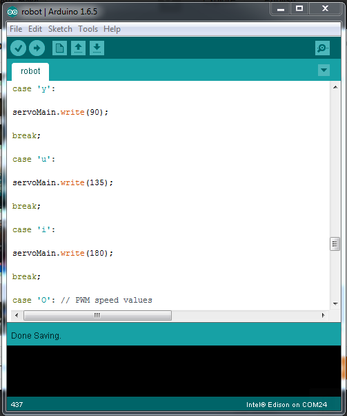
To upload the code you need the Arduino IDE with the Intel Edison plug in, the code to be uploaded can be found below. The Intel Edison Plugin can be installed from the Arduino IDE board manager by installing the Intel x86 package. Make sure you have the chose the right port while uploading the code to the board.
#include
Servo servoMain;
float temp;
int tempPin = 0;
int r_motor_n = 4; //PWM control Right Motor -
int r_motor_p = 5; //PWM control Right Motor +
int l_motor_p = 6; //PWM control Left Motor +
int l_motor_n = 7; //PWM control Left Motor -
int enable = 3;
int light = 9;
int enable2 = 6; //PWM CONTROL SPEED
int speed1 = 0; // PWM controll speed
int incomingByte = 0; // for incoming serial data
#include
#define TRIGGER_PIN 12 // Arduino pin tied to trigger pin on the ultrasonic sensor.
#define ECHO_PIN 11 // Arduino pin tied to echo pin on the ultrasonic sensor.
#define MAX_DISTANCE 200 // Maximum distance we want to ping for (in centimeters). Maximum sensor distance is rated at 400-500cm.
NewPing sonar(TRIGGER_PIN, ECHO_PIN, MAX_DISTANCE); // NewPing setup of pins and maximum distance.
void setup()
{
servoMain.attach(10);
pinMode(r_motor_n, OUTPUT); //Set control pins to be outputs
pinMode(r_motor_p, OUTPUT);
pinMode(l_motor_p, OUTPUT);
pinMode(l_motor_n, OUTPUT);
pinMode(enable, OUTPUT);
pinMode(enable2, OUTPUT);
pinMode(light, OUTPUT);
digitalWrite(r_motor_n, LOW); //set both motors off for start-up
digitalWrite(r_motor_p, LOW);
digitalWrite(l_motor_p, LOW);
digitalWrite(l_motor_n, LOW);
digitalWrite(enable, LOW);
digitalWrite(enable2, LOW);
digitalWrite(light, HIGH);
Serial.begin(9600);
Serial.print("Whats up im ATOM, geared up!!!! \n");
Serial.print("w = Forward \n");
Serial.print("s = Backward \n");
Serial.print("d = Right \n");
Serial.print("a = Left \n");
Serial.print("f = Stop \n");
Serial.print("lame freaks robotics");
}
void loop()
{
if (Serial.available() > 0) {
// read the incoming byte:
incomingByte = Serial.read();
}
switch(incomingByte)
{
case 'S': // control to stop the robot
digitalWrite(r_motor_n, LOW); //Set motor direction, 1 low, 2 low
digitalWrite(r_motor_p, LOW);
digitalWrite(l_motor_p, LOW);
digitalWrite(l_motor_n, LOW);
analogWrite(enable, 0);
analogWrite(enable2, 0);
Serial.println("Stop\n");
incomingByte='*';
break;
case 'R': //control for right
digitalWrite(r_motor_n, HIGH); //Set motor direction, 1 high, 2 low
digitalWrite(r_motor_p, LOW);
digitalWrite(l_motor_p, HIGH);
digitalWrite(l_motor_n, LOW);
analogWrite(enable, speed1);
analogWrite(enable2, speed1);
Serial.println("right\n");
incomingByte='*';
break;
case 'L': //control for left
digitalWrite(r_motor_n, LOW); //Set motor direction, 1 low, 2 high
digitalWrite(r_motor_p, HIGH);
digitalWrite(l_motor_p, LOW);
digitalWrite(l_motor_n, HIGH);
analogWrite(enable, speed1);
analogWrite(enable2, speed1);
Serial.println("left\n");
incomingByte='*';
break;
case 'F': //control for forward
digitalWrite(r_motor_n, HIGH); //Set motor direction, 1 high, 2 high
digitalWrite(r_motor_p, LOW);
digitalWrite(l_motor_p, LOW);
digitalWrite(l_motor_n, HIGH);
analogWrite(enable, speed1);
analogWrite(enable2, speed1);
Serial.println("forward\n");
incomingByte='*';
break;
case 'B': //control for backward
digitalWrite(r_motor_n, LOW); //Set motor direction, 1 low, 2 low
digitalWrite(r_motor_p, HIGH);
digitalWrite(l_motor_p, HIGH);
digitalWrite(l_motor_n, LOW);
analogWrite(enable, speed1);
analogWrite(enable2, speed1);
Serial.println("backwards\n");
incomingByte='*';
break;
case 'f':
digitalWrite(r_motor_n, LOW); //Set motor direction, 1 low, 2 low
digitalWrite(r_motor_p, LOW);
digitalWrite(l_motor_p, LOW);
digitalWrite(l_motor_n, LOW);
analogWrite(enable, 0);
analogWrite(enable2, 0);
Serial.println("Stop\n");
incomingByte='*';
break;
case 'd':
digitalWrite(r_motor_n, HIGH); //Set motor direction, 1 high, 2 low
digitalWrite(r_motor_p, LOW);
digitalWrite(l_motor_p, HIGH);
digitalWrite(l_motor_n, LOW);
analogWrite(enable, speed1);
analogWrite(enable2, speed1);
Serial.println("right\n");
incomingByte='*';
break;
case 'a':
digitalWrite(r_motor_n, LOW); //Set motor direction, 1 low, 2 high
digitalWrite(r_motor_p, HIGH);
digitalWrite(l_motor_p, LOW);
digitalWrite(l_motor_n, HIGH);
analogWrite(enable, speed1);
analogWrite(enable2, speed1);
Serial.println("left\n");
incomingByte='*';
break;
case 'w':
digitalWrite(r_motor_n, HIGH); //Set motor direction, 1 high, 2 high
digitalWrite(r_motor_p, LOW);
digitalWrite(l_motor_p, LOW);
digitalWrite(l_motor_n, HIGH);
analogWrite(enable, speed1);
analogWrite(enable2, speed1);
Serial.println("forward\n");
incomingByte='*';
break;
case 's':
digitalWrite(r_motor_n, LOW); //Set motor direction, 1 low, 2 low
digitalWrite(r_motor_p, HIGH);
digitalWrite(l_motor_p, HIGH);
digitalWrite(l_motor_n, LOW);
analogWrite(enable, speed1);
analogWrite(enable2, speed1);
Serial.println("backwards\n");
incomingByte='*';
break;
case 'r': // servo angles
servoMain.write(0);
break;
case 't':
servoMain.write(45);
break;
case 'y':
servoMain.write(90);
break;
case 'u':
servoMain.write(135);
break;
case 'i':
servoMain.write(180);
break;
case 'O': // PWM speed values
speed1 = 0 ;
break;
case '1':
speed1 = 155;
break;
case '2':
speed1 = 165;
break;
case '3':
speed1 = 175;
break;
case '4':
speed1 = 185;
break;
case '5':
speed1 = 195;
break;
case '6':
speed1 = 205;
break;
case '7':
speed1 = 215;
break;
case '8':
speed1 = 225;
break;
case '9':
speed1 = 235;
break;
case 'q':
speed1 = 255;
break;
case 'm':
temp = analogRead(tempPin); // Read the temperature
temp = temp * 0.48828125;
Serial.print("TEMPRATURE = ");
Serial.print(temp);
Serial.print("*C");
Serial.println();
delay(1000);
break;
case 'p': // time to ping thr ultasonic sensor
delay(50); // Wait 50ms between pings (about 20 pings/sec). 29ms should be the shortest delay between pings.
unsigned int uS = sonar.ping(); // Send ping, get ping time in microseconds (uS).
Serial.print("Ping: ");
Serial.print(uS / US_ROUNDTRIP_CM); // Convert ping time to distance in cm and print result (0 = outside set distance range)
Serial.println("cm");
break;
delay(5000);
}
}
Downloads
Test


After uploading the code it is time to take it on a test ride, you can control the robot via an android phone and an android app or a terminal emulator (like putty) on a PC. The apk file to be installed can be found below, make sure you have set your phone to install apks from unknown sources. The controls are listed on the app and on the terminal applications as well.
Stream Videos

This step is if your are using a web cam along with the Intel Edison, if you are using a IP camera or a mobile phone you can skip this step.
Now it is time to get the Intel Edison to stream videos, to web browser. We need to install a package called mjpg streamer. To do that we need to open the debug port of the Intel Edison on a terminal emulator and enter the following commands into it.
opkg install mjpg-streamer<br>
And to view the video output type in
mjpg_streamer -i "input_uvc.so -y -n -f 30 -r 640x480" -o "output_http.so -p 8080 -n -w /www”
Then open up a web browser and enter the IP address of the Intel Edison board.