Ilustrated CAD Process for Creating a 3D Printed Assistive Device in ABS Plastic
by siderits in Workshop > 3D Printing
5345 Views, 8 Favorites, 0 Comments
Ilustrated CAD Process for Creating a 3D Printed Assistive Device in ABS Plastic
Experimental Pathology and Parabiotics Research team:
Team: R. Siderits, M. Riad
Abstract: This project illustrates the basic CAD techniques and steps needed to design and prototype an assistive device (right angles Spoon) using a 3D printer in ABS plastic.
Team: R. Siderits, M. Riad
Abstract: This project illustrates the basic CAD techniques and steps needed to design and prototype an assistive device (right angles Spoon) using a 3D printer in ABS plastic.
Designing a Right Angle Spoon for 3D Printing
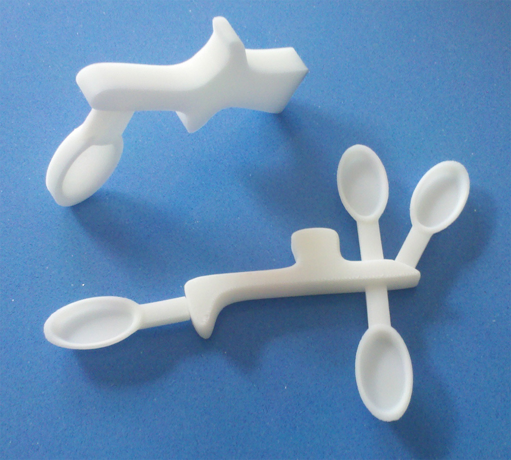
Abstract:
This Instructable will demonstrate some basic design steps used in 3D prototyping of a right angle spoon for 3D printing.
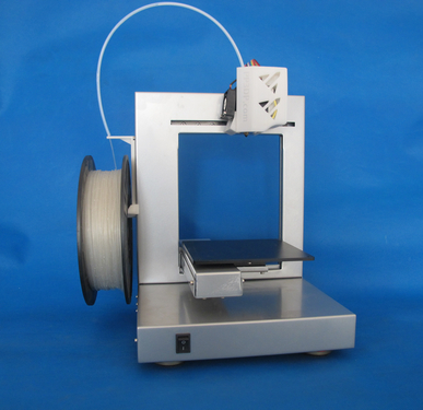
The 3D printer that we used was an UP!3D and the material is ABS plastic.
The take home point of this Instructable is that even with only basic knowledge of 3D design and some free CAD software, anyone can design and prototype a broad range of simple assistive devices for people with disabilities, essentially in real time and at a cost of next to nothing.
There are tens of thousands of "Parametric" files available online for download and printing on 3D printers (parametric files just save the information needed to 3D print the object, STL format example, in the real world). Places like Thingiverse.com or TED TV 3D printing are good resources to learn about how 3D printing is redefining manufacturing and distribution on a global scale.
The design process took about 90 seconds, the printing about 20 minutes and the cost was under 3 cents.
Don't worry about speed in designing with a CAD program or the particular program that you use, that comes with familiarity with your 3D CAD program. You don't have to spend as much time looking for the right buttons and you have the basic experience to know how to construct the object that you want to make. This is a fun example of those basic concepts.
Team:
Experimental Pathology Team in conjunction with the Parabiotics Research team:
Rendering of Final Design
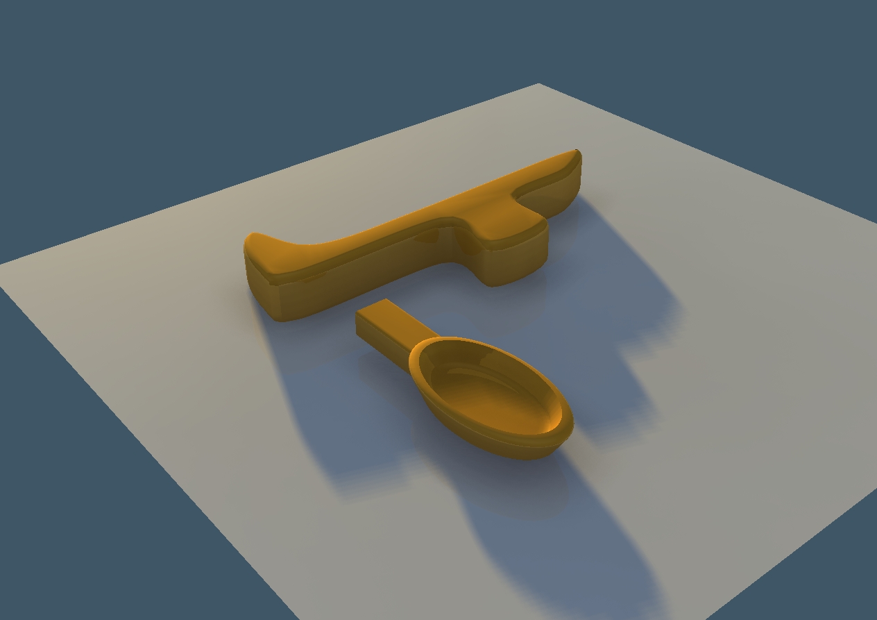
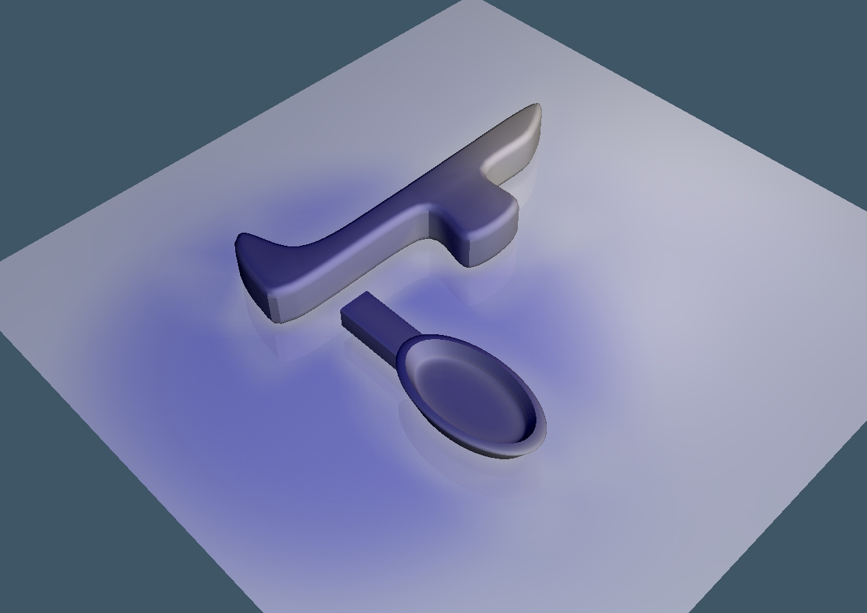
Here is a rendered scene from the CAD (computer assisted design) program.
We'll walk through the design steps, one by one.
There are lots of free CAD programs including Google Sketchup.
The one we used is trueSpace. Don't worry about it being different than the one you use.
They all have the same principles: take simple objects called "primatives" like cubes, rods, toroids (donuts), and spheres; then fuse or subtract them to make more complex structures.
Step 1: Open the CAD Program
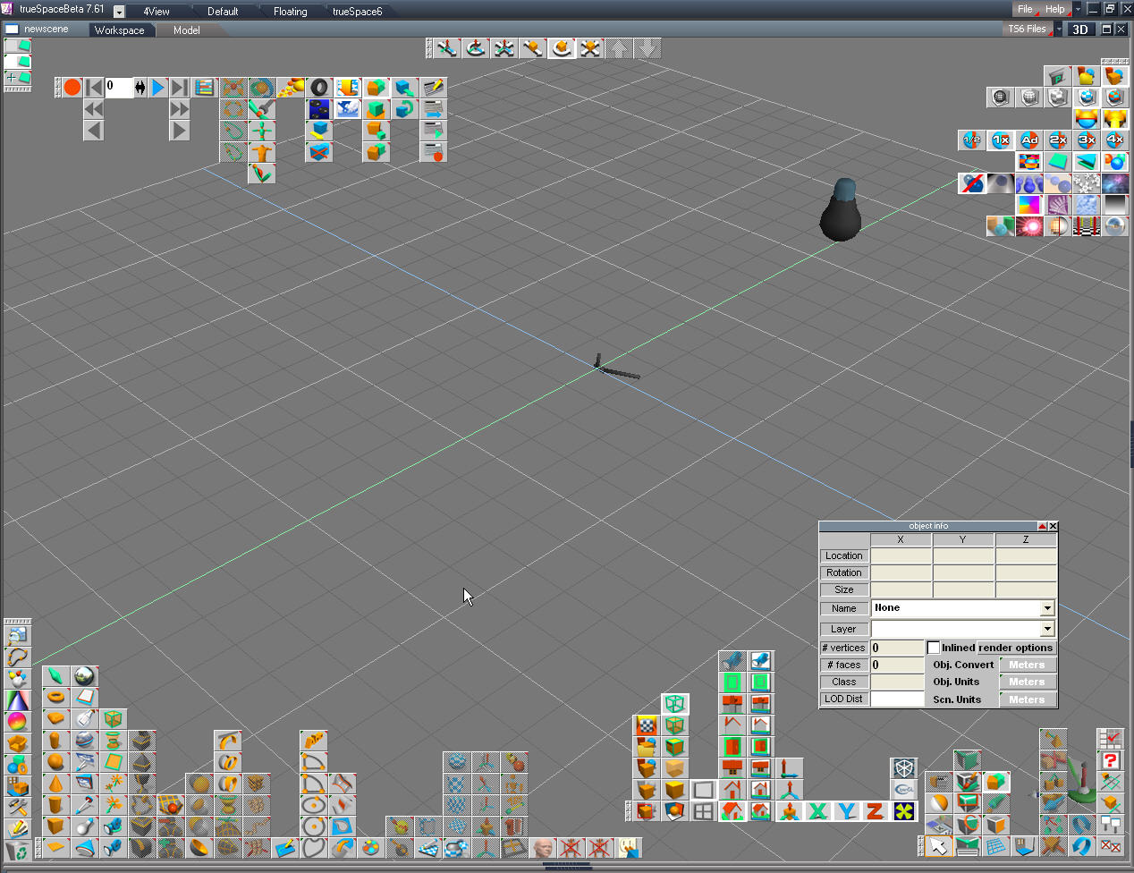
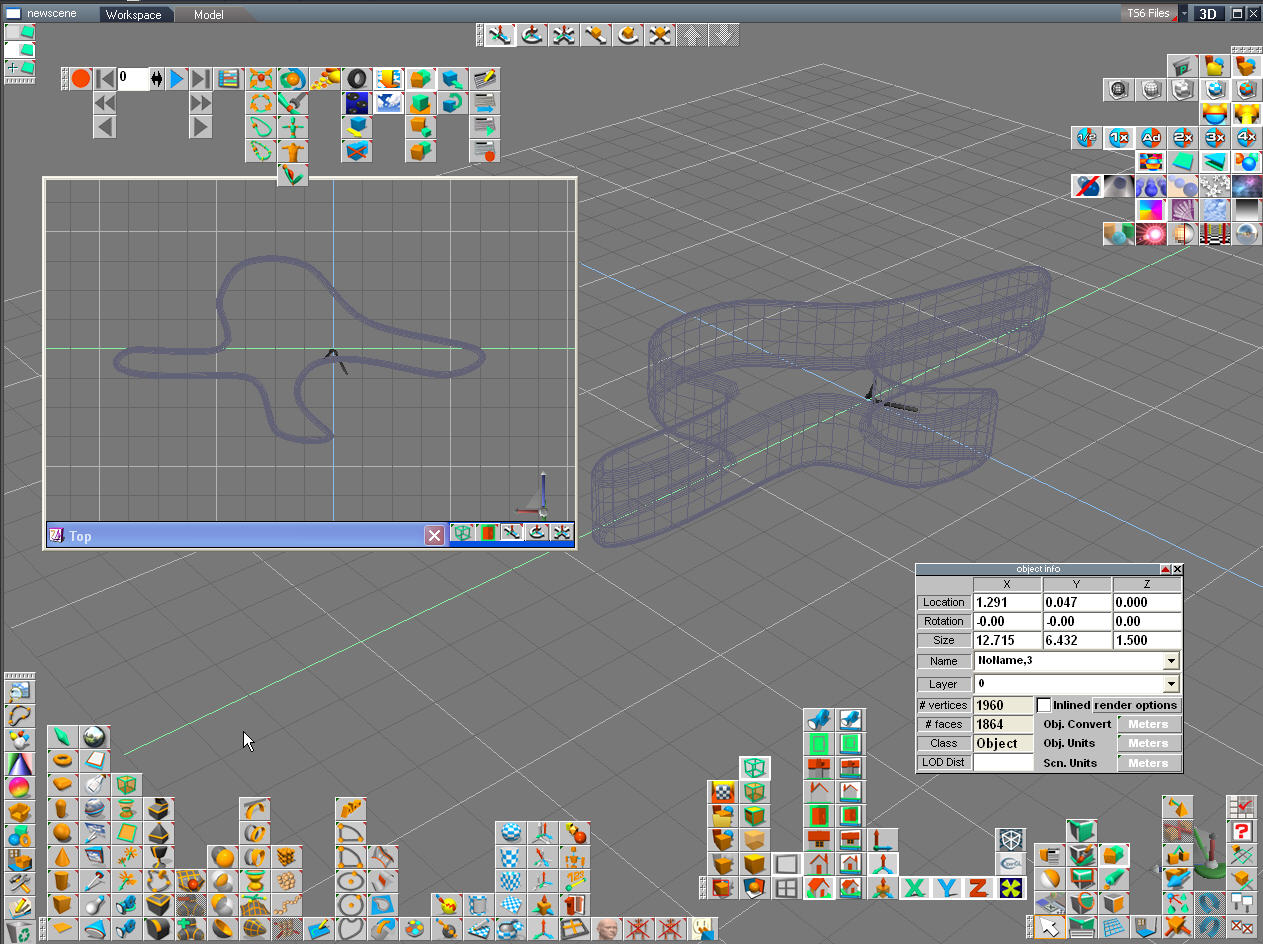
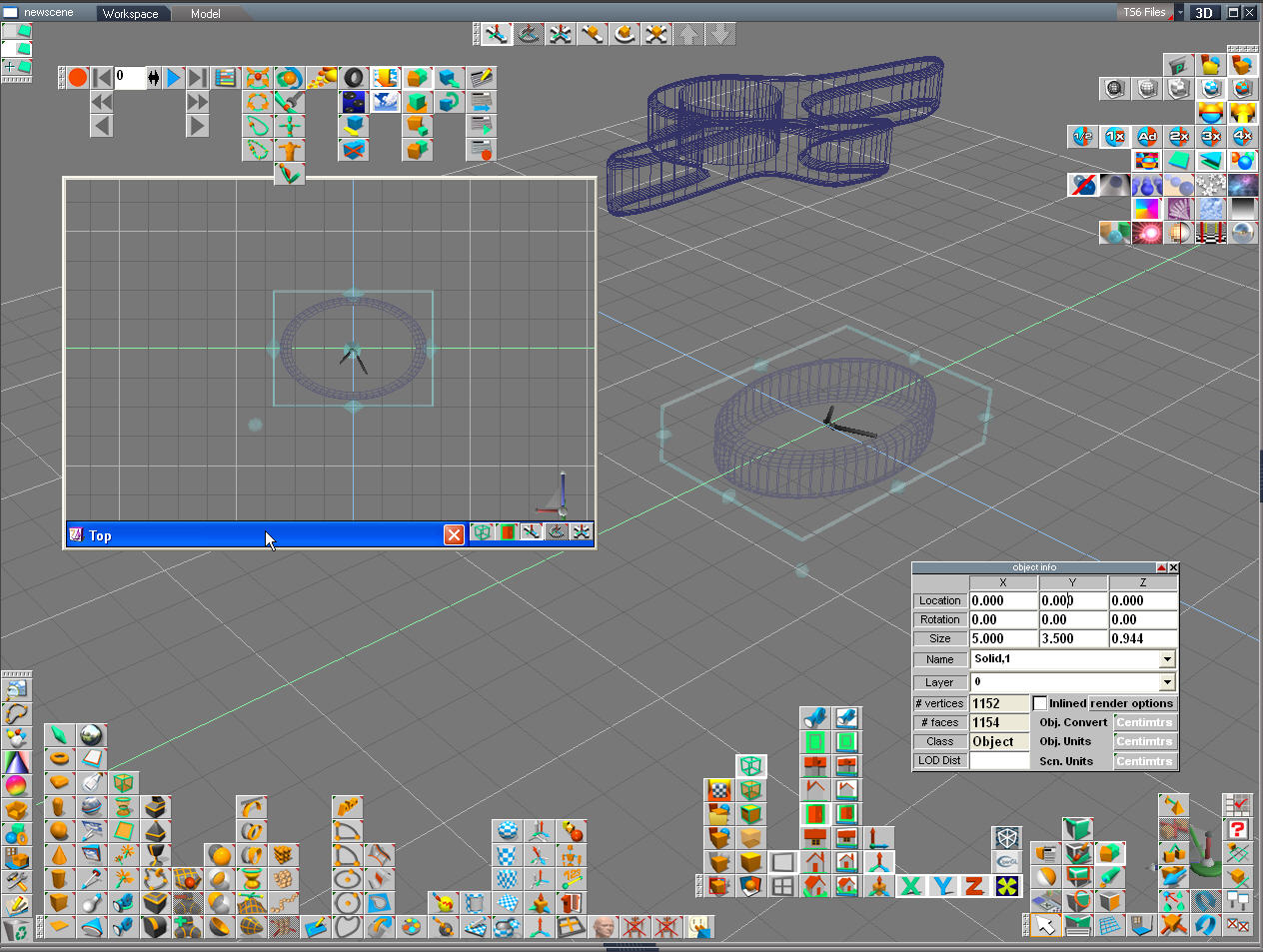
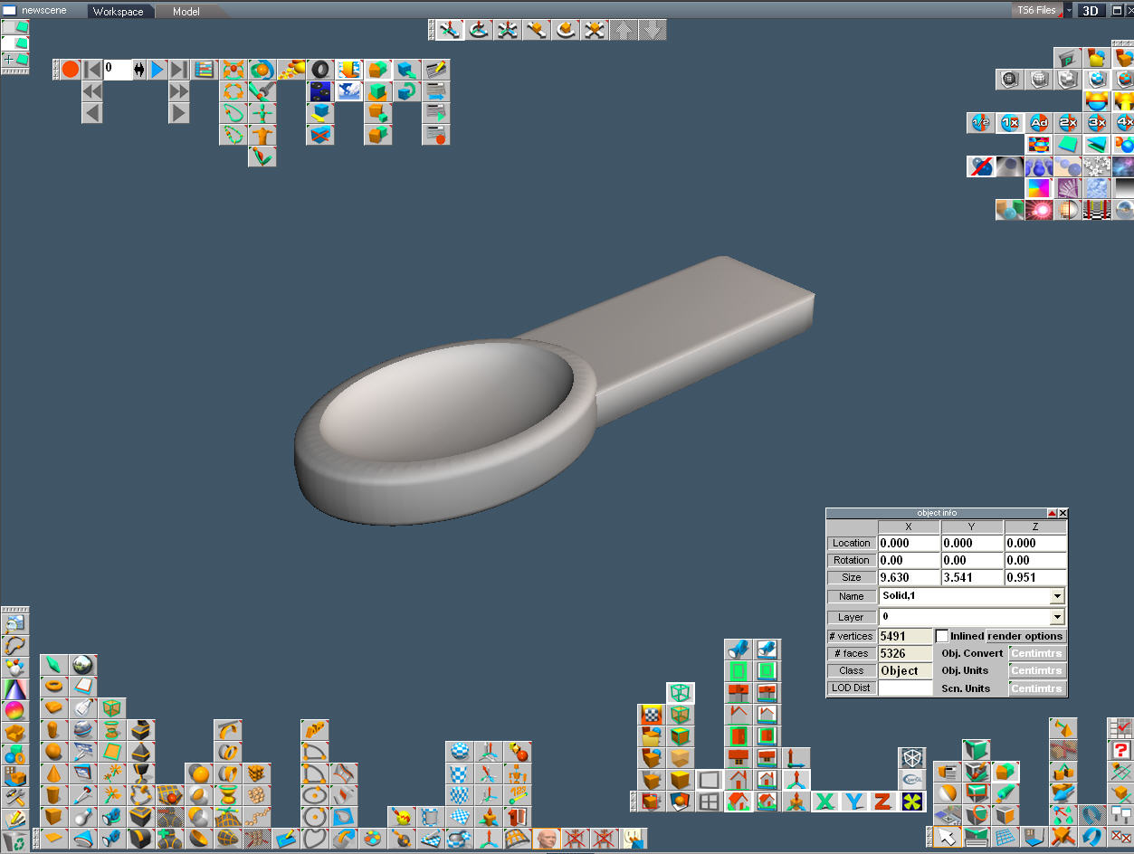
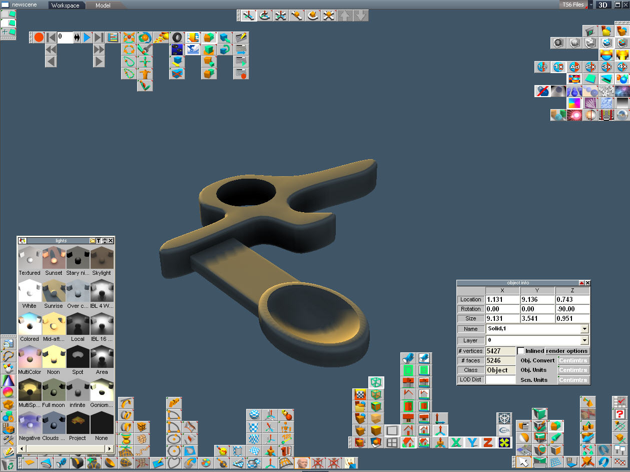


Here we have an empty plane and a digital Universe waiting for us to populate it with new things.
All of the buttons represent different ways of interacting with the objects that you create.
Every program has different controls. Don't get hung up on the details. Keep the basic idea that
they're all the same, they just look different.
This is the main screen for trueSpace. The tow arrow shaped thing in the center represent light sources in the virtual environment.
This is the stage that we'll build on.
Step 2: Open a Draw Panel

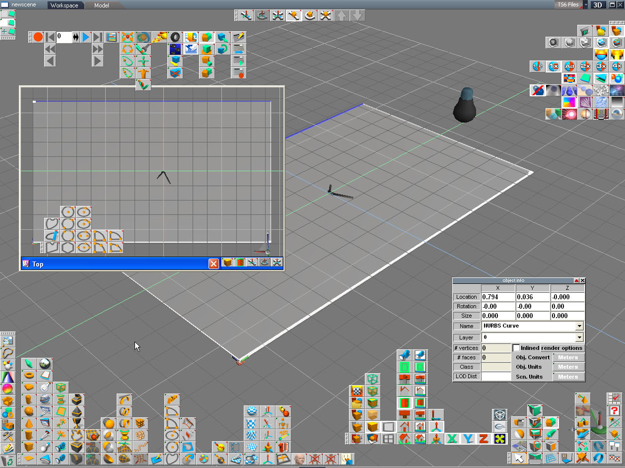
A draw panel lets us draw shapes and pull and push the points that outline the shape until its just right.
The littler window on the left is just another view of the same space but from the top. Most CAD programs let you look at
what you are doing form multiple angles.
The littler window on the left is just another view of the same space but from the top. Most CAD programs let you look at
what you are doing form multiple angles.
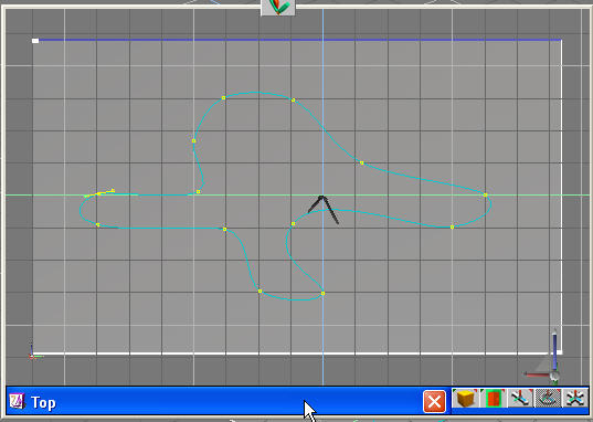
Step 3: Put Down Some Points That Will Outline Our Shape.

For example here is a free style spoon handle. When you have a basic shape hit the "close curve" button to close the outline of your shape. Now if you select any of the points on the curve you can drag them into new positions or change how to represent the curve. Like a Bezier function (see Wikipedia). Remember that this outline is as thin as a plane. We haven't given it any thickness yet.
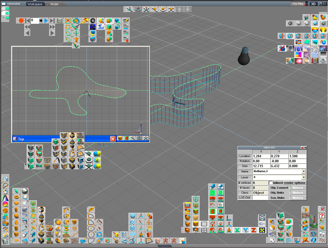
Step 4: Give the Outline Thickness

Next we will choose the "Sweep" function button to extrude the surface and give the outline some thickness.
Step 5: Subracting a Volume

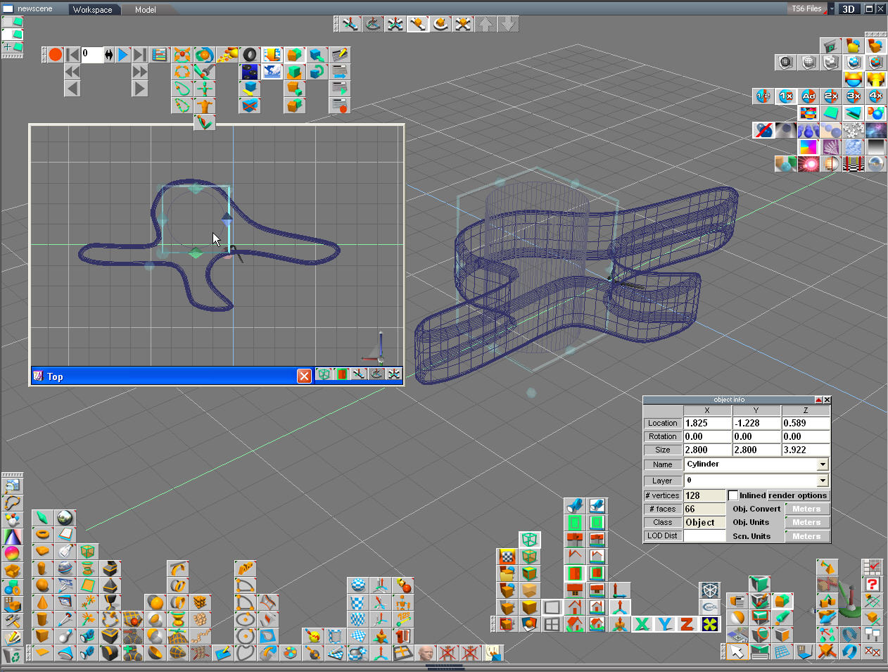
Next we'd like to bevel or round the top and bottom surface. Click the right mouse button on the object to slect the surface that you want to bevel then use the "filet tool". Change the amount of curve to fit your need in the tool's parameters.
Next, if we want a hole in the object we need to subtract something from it, see next step.
Next, if we want a hole in the object we need to subtract something from it, see next step.
Step 6: Making a Hole

To make a hole we need to subtract a cylinder (one of our "primitives").
I created a new cylinder object and positioned it over our handle. I looked at the space from the side to make sure that the cylinder was positioned across the outline of the handle. Then I selected the handle as the active object by clicking on it and hit the "Subtract volume" button then selected the cylinder. The cylinder was then subtracted from the handle, leaving a hole behind.
I created a new cylinder object and positioned it over our handle. I looked at the space from the side to make sure that the cylinder was positioned across the outline of the handle. Then I selected the handle as the active object by clicking on it and hit the "Subtract volume" button then selected the cylinder. The cylinder was then subtracted from the handle, leaving a hole behind.
Step 7: Render the Scene

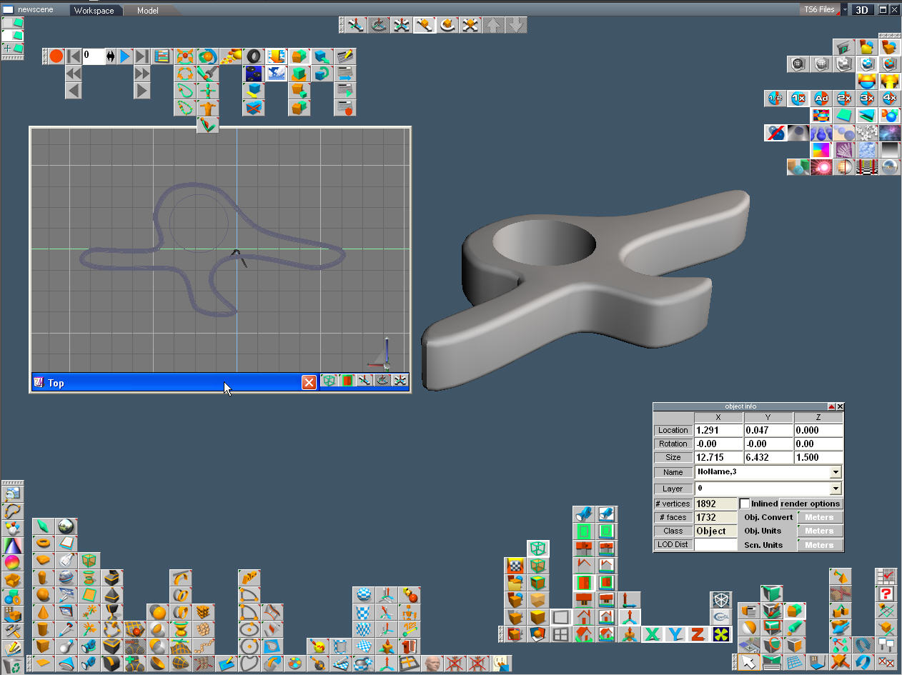
Its a good idea to render the scene every once in a while, while you work to make sure that everything is the way you think it looks in the wire frame representation.
Step 8: Use the Same Principles to Make the Spoon

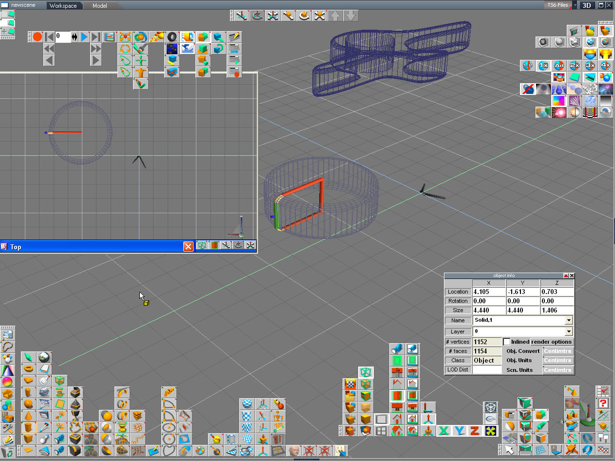
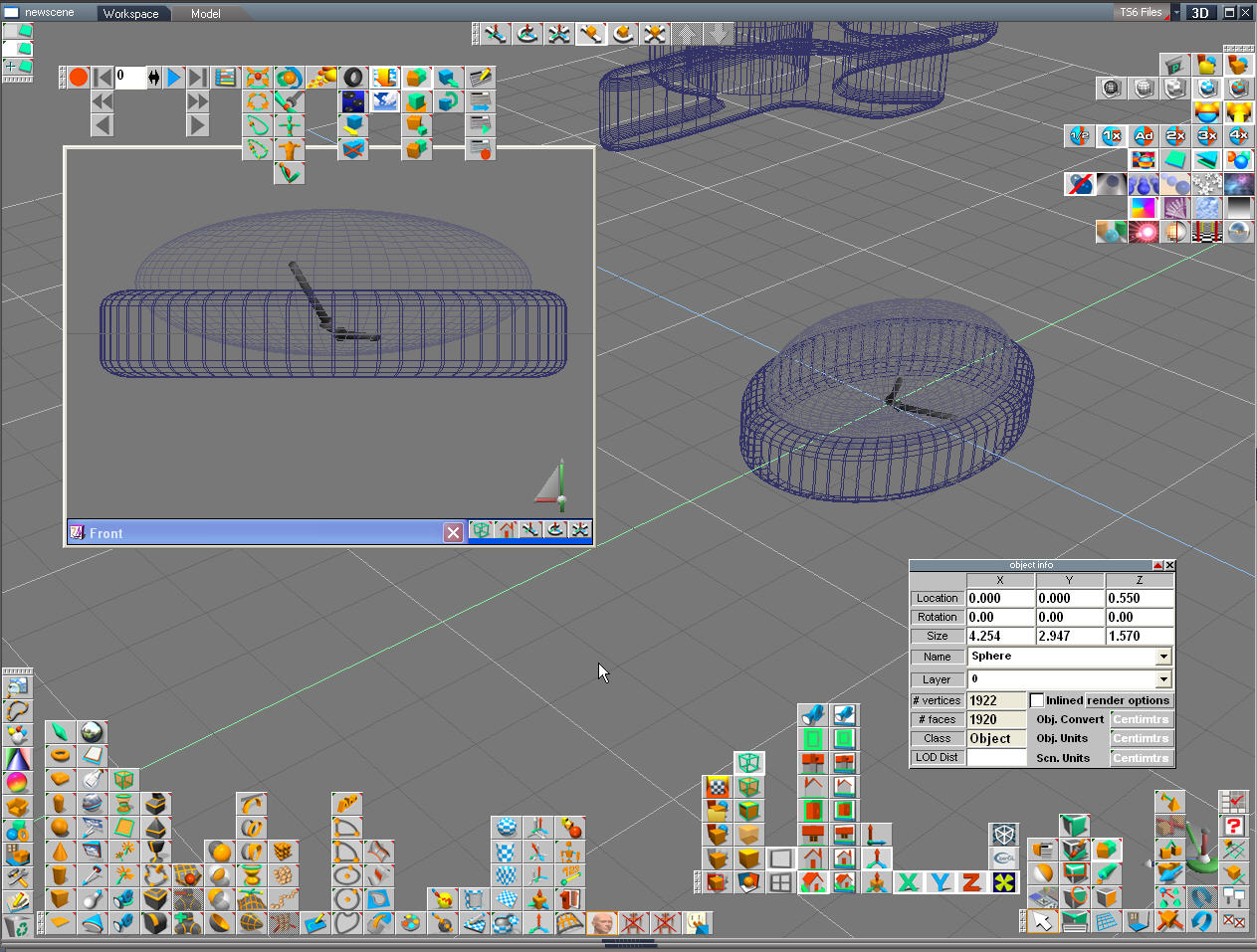
We'll use the same principles to design the spoon. Start with a cylinder. We'll skew or distort the cylinder so that its more oval or spoon shaped. Most CAD programs will let you drag a control to distort but I tend to do things the old fashioned way with the dimensioning panel open so I can put in values.
Here is the cylinder that we'll use. When you create a new primitive of the cylinder it will let you round the edges, tip the sides, resize the object and lots of other useful things.
Here is the cylinder that we'll use. When you create a new primitive of the cylinder it will let you round the edges, tip the sides, resize the object and lots of other useful things.
Step 9: Make the Cylinder Look More Like a Spoon

Here is where we stretch the cylinder to look more like the end of a spoon.
Step 10: Make a Hoolo Space for the Spoon

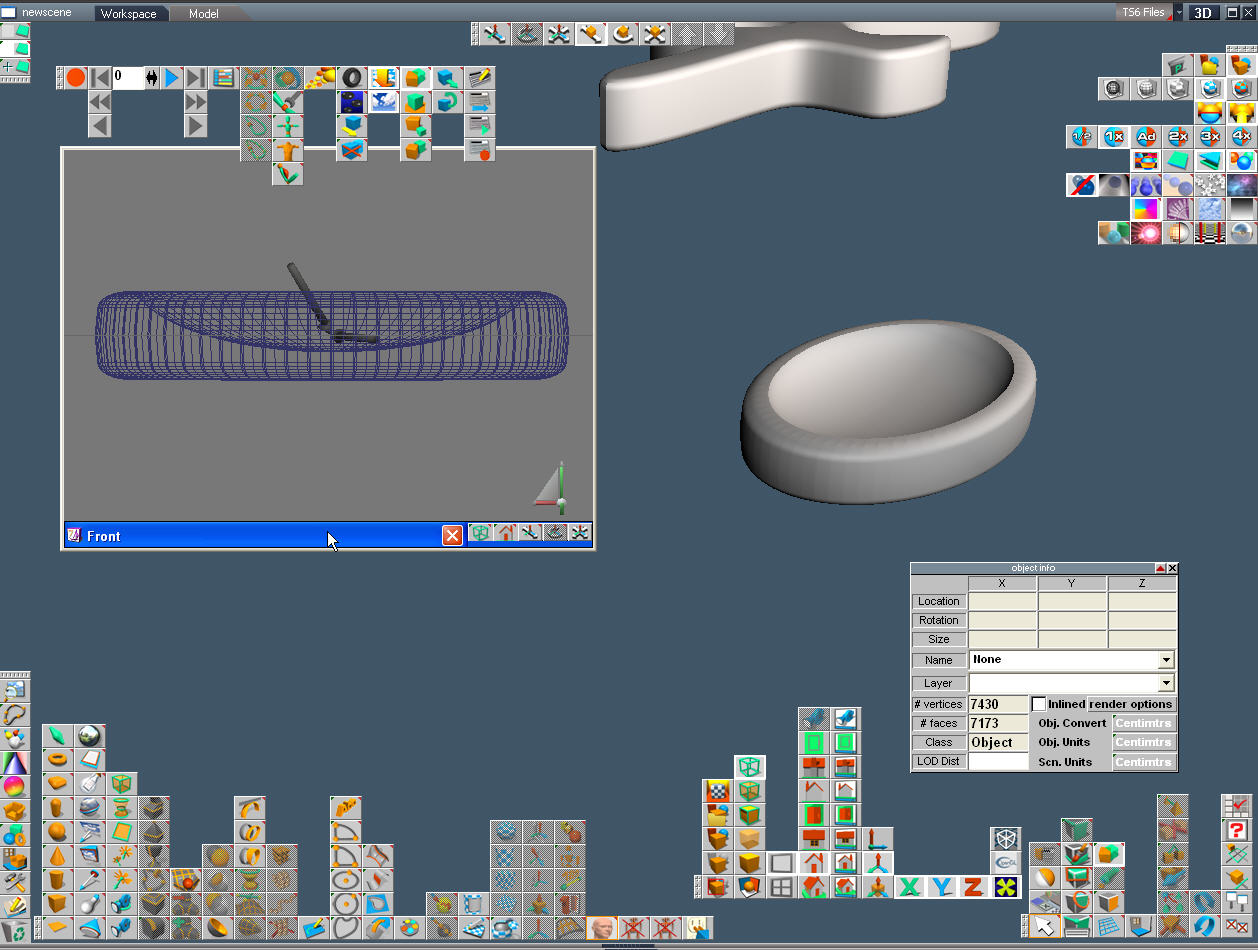
Now we create a sphere and distort it to be more ovoid.
Use the same technique as before to subtract the ovoid from the stretched cylinder.
Use the same technique as before to subtract the ovoid from the stretched cylinder.
Step 11: Render the Scene

Looks good, now instead of subtracting something, lets add a short handle for the spoon.
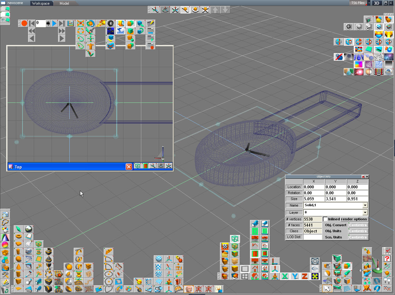
Step 12: Create a Short Handle

This time we create a new box or cube primitive but we drag it in different directions to get it to be a rectangular shape with beveled surfaces and thinner than the spoon head. Next select the "Fuse"or Object Union button and merge the two objects by clicking on one, the fuse button then the other.
Step 13: Render the Object

Good, looks more or less like a spoon. We might consider rounding the inner lip and tilting the sides but this will do for an example.
Step 14: Render the Scene for Publication.

Choose "sunset" lighting from the lighting panel and a nice surface "texture" or appearance from the material library. Alter the appearence of the surface by changing colors, shininess, reflectivity, bump mapping etc.
Using cyanomethachrolate glue, you can now stick the handle to the spoon at any level to fit your purpose.


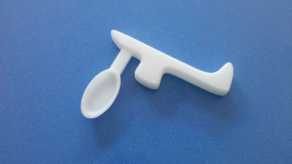
This is the Final version (until someone wants some new feature or modification) for the Right Angle Spoon that we designed.
The bump on the front rests at the base of the thumb and provides support and the tail rests against the pinky to give lateral stability.
The design process took about 90 seconds. Don't worry about speed, that comes with familiarity with your 3D CAD program. You don't have to spend as much time looking for the right buttons and you have the basic experience to know how to construct the object that you want to make.
First we saved the scene in trueSpace so that we could go back and make changes to these objects any time in the future.
Next we saved our individual objects out of the 3D CAD program (trueSpace) as STL or Stereo lithography files.
Next we opened the individual files in the UP!3D Printer software and hit "Print".
That's about it. 20 minutes later there was a solid plastic object sitting on the platform of the 3D printer.
From design to holding the prototype was 22 minutes and we had time to ask for suggestions about how to alter the objects in the CAD program for the next print.
At about 0.2 cents per gram (35$ for a 1kg spool of 1.75 mm ABS plastic) the prototype weighed 14.4 grams and cost about 3 cents to make.
You can print multiple copies of both parts at a time to make different attachments.
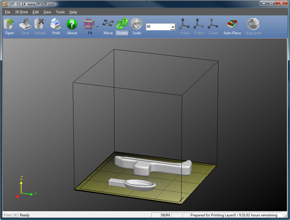
Here are our spoon STL files that we designed earlier.
They are now in the software for the Up!3D printer and are ready to go.
The second image is of the Up!3D printer. This is one of several low cost printers available for home hobby use.
They vary in price from 500-3,000 $ and are all essentially comparable, with minor feature variations and
extent of DIY-edness.
The End...
Thanks!