IR Wand Automated Lumos Lamp

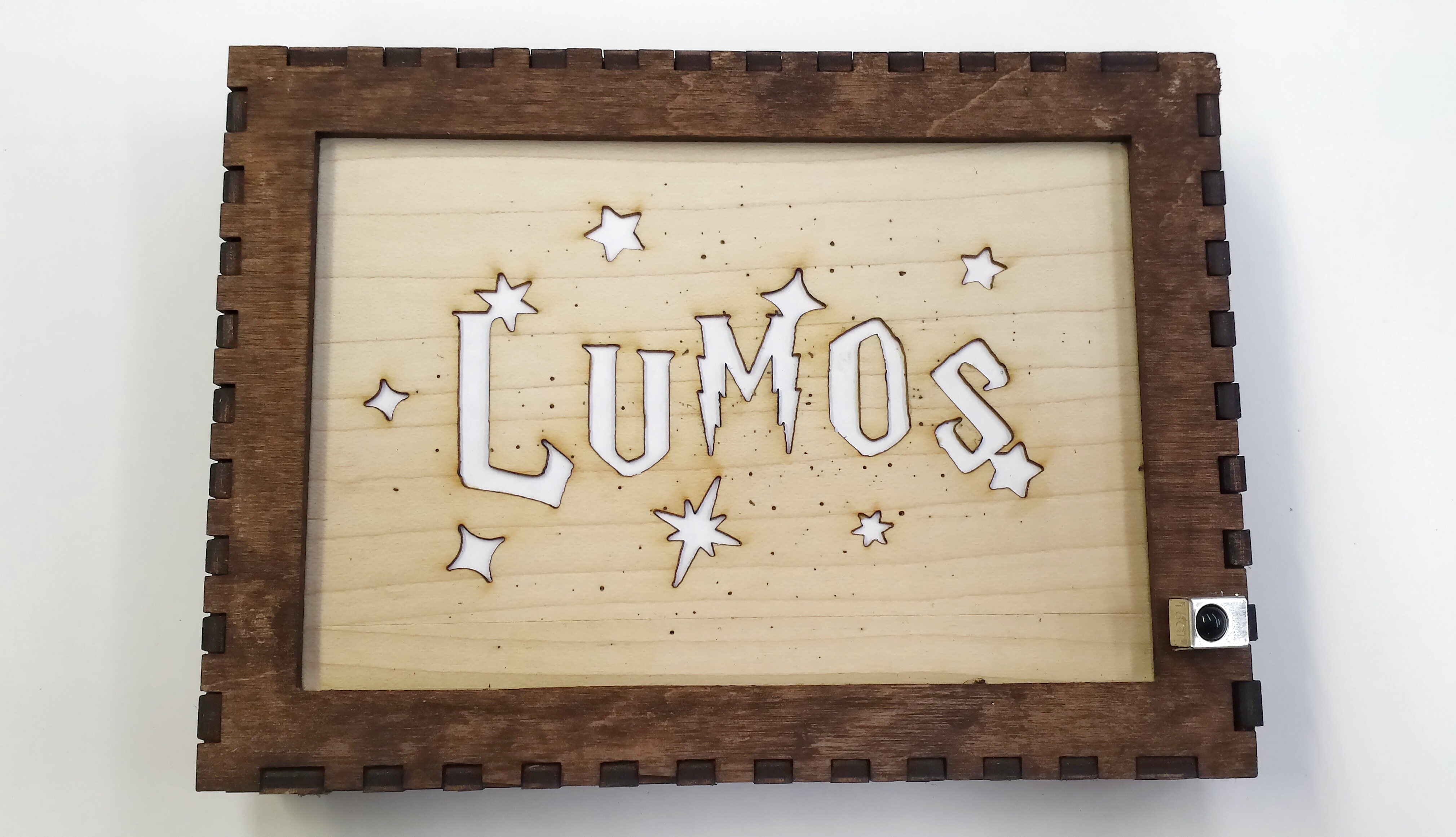
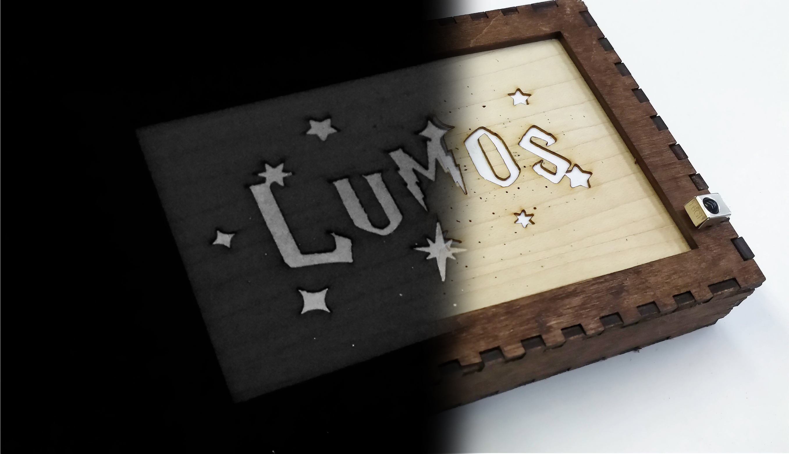
Why walk over to the light switch when you can cast Lumos with the flick of a wand?
This Lumos light houses an infrared (IR) sensor that powers the LED strip when the sensor picks up on waves emitted from an IR bulb inside a wand. This project was inspired by a desire to learn more about electronic components: I wanted to try out IR sensors and design a circuit implementing them. Another interesting feature of this project is homemade LED sequins: I wanted to test the efficacy of soldering surface mount LEDs to solder wick loops before sewing them onto leather to create LED strips (hint: success). See below for an attached video on the pulsing lights.
Because this was a quick prototype of concepts (just proving concepts for now, but fully robust circuit to be done possibly in the future), I used minimal electronic equipment and just what I had on hand so as to avoid breaking the bank. That being said, noise is a bit of a problem for this circuit (in fact, there are lots of little electronic hand-wavy parts), but I'll discuss ways to optimize the electronics in the last step of the tutorial.
Downloads
What Is an IR Sensor?
Infrared is a type of emitted light with wavelengths ranging from ~800nm-1mm. This light is not part of the visible light spectrum (no, it's not ROYGBIV: Red Orange Yellow Green Blue Infrared Violet.. I is for Indigo) so you can't see it with the naked eye, but what you can do is hold a TV remote (remotes generally use IR to communicate with their corresponding devices) under your phone's camera and you should see the LED blinking.
Why is the TV remote's LED blinking? That's because the LED is modulated to a certain pulse frequency. The concept is called pulse width modulation: PWM. It's a way to get analog results from digital ones (getting gray from black and white). Digital signals are either on or off -- for an LED, the LED is bright or it's not. To get an analog signal, you pulse between on and off -- for an LED, changing the ratio of time that it is on vs. off makes the LED seem brighter or darker.
The IR sensor that I used (and most others) is tuned to detect 38kHz frequency emissions, though it has a range of close PWM frequencies that it detects as well (varies sensor to sensor). This leads to noise that your sensor may pick up, and thus if you connect an LED to the sensor it might flash on and off randomly since it picks up random IR signals in the environment.
The sensor usually has three pins: one supply voltage pin (battery positive terminal), one supply ground pin (battery negative terminal), and one output pin (outputs the voltage to power another circuit, in this case LEDs). I have more on how to hook up the circuit in step 8.
For more info, this is a really helpful tutorial from Adafruit with an overview of IR sensors.
Materials
- 5050 surface mount LEDS (I made my own LED sequins since adafruit sells 5 for $4 and I can buy 100 surface mount LEDs for $5)
- leather (as a flexible backing of my LED strip
- solder wick (to make flexible loops attached to the surface mounts to turn them into sequins)
- soldering iron (+ optional helping hands)
- IR sensor
- IR LED
- breadboard for testing circuit
- plastic-coated wire
- laser cutter (I used UMaker's Full Spectrum, hobby 20x12in 40W laser in Claremont, CA)
- 1/8" birch (or just wood for the light's frame)
- veneer (I liked it for cutting my design out, but up to you)
- paper (to put behind your design cutouts so that it diffuses the light inside)
Design
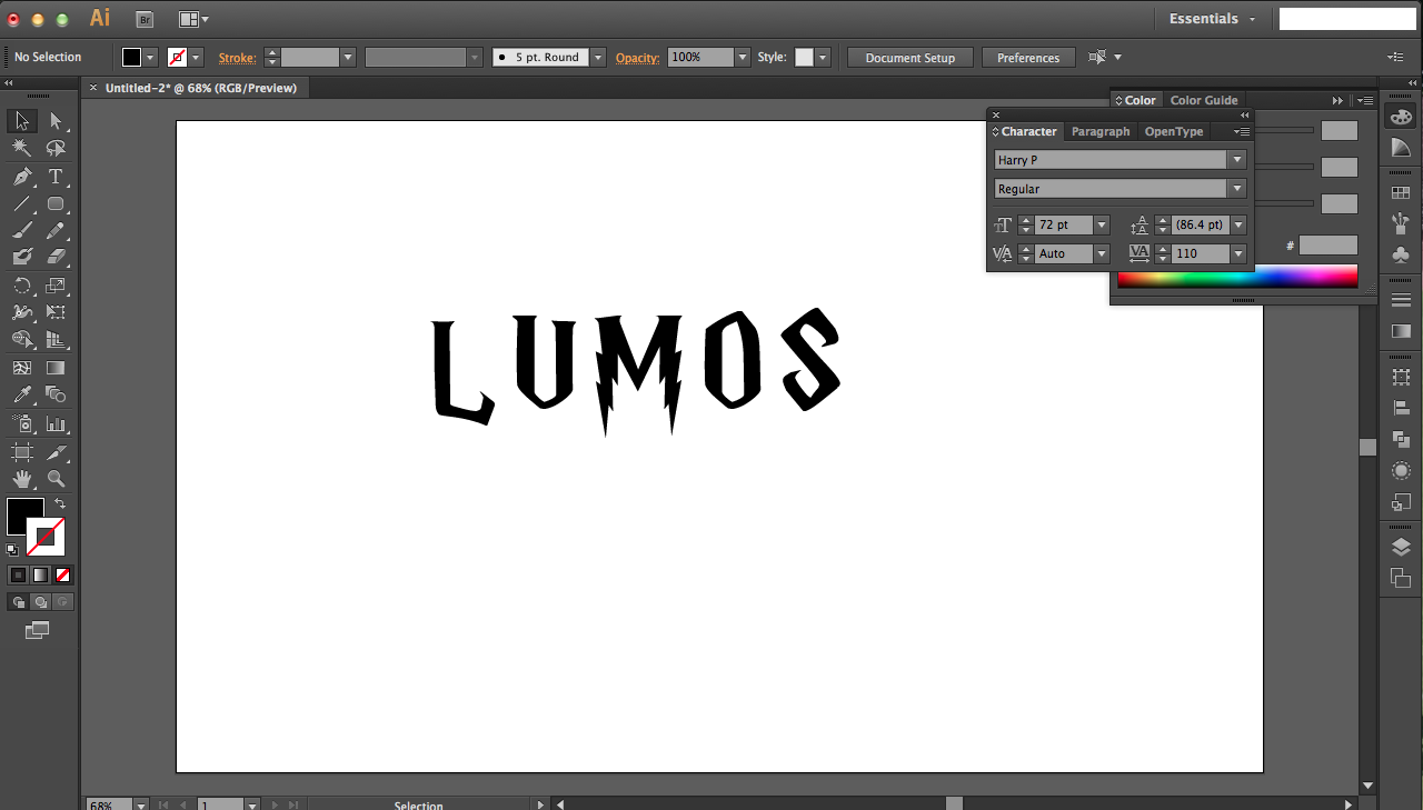
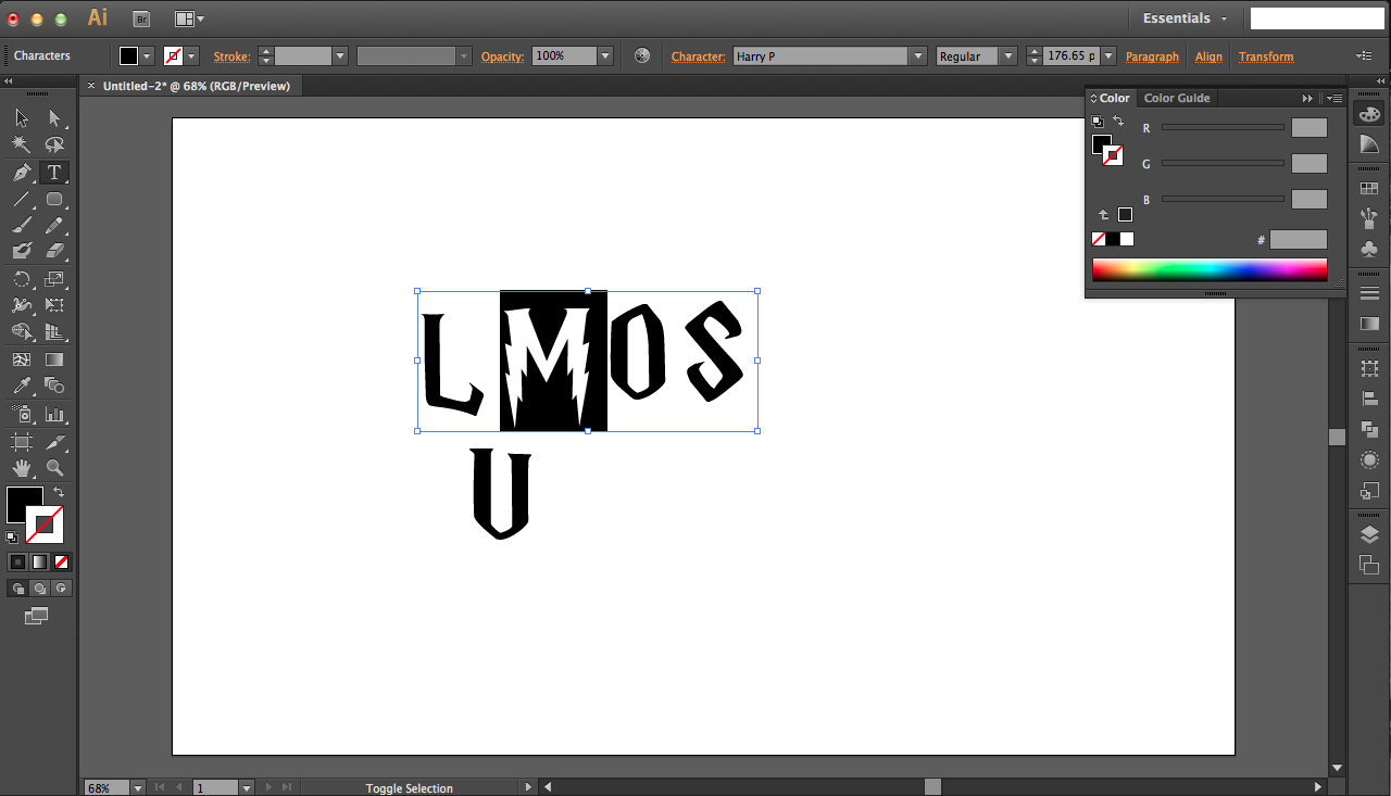
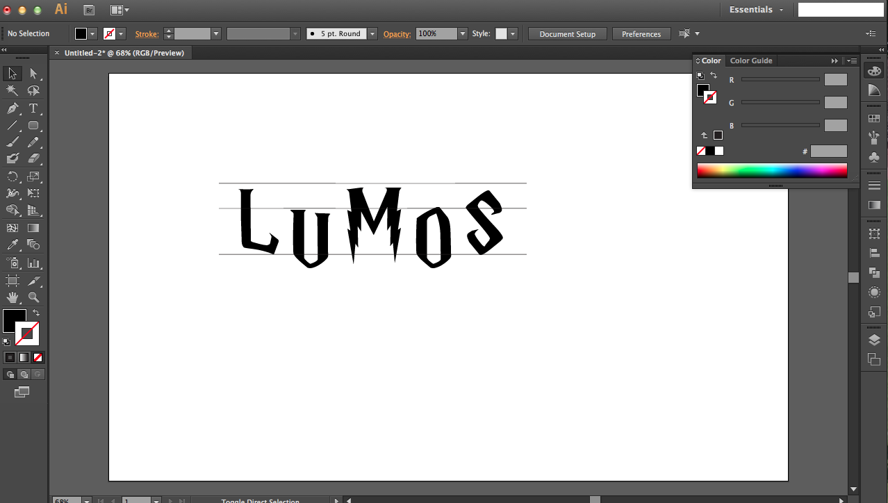
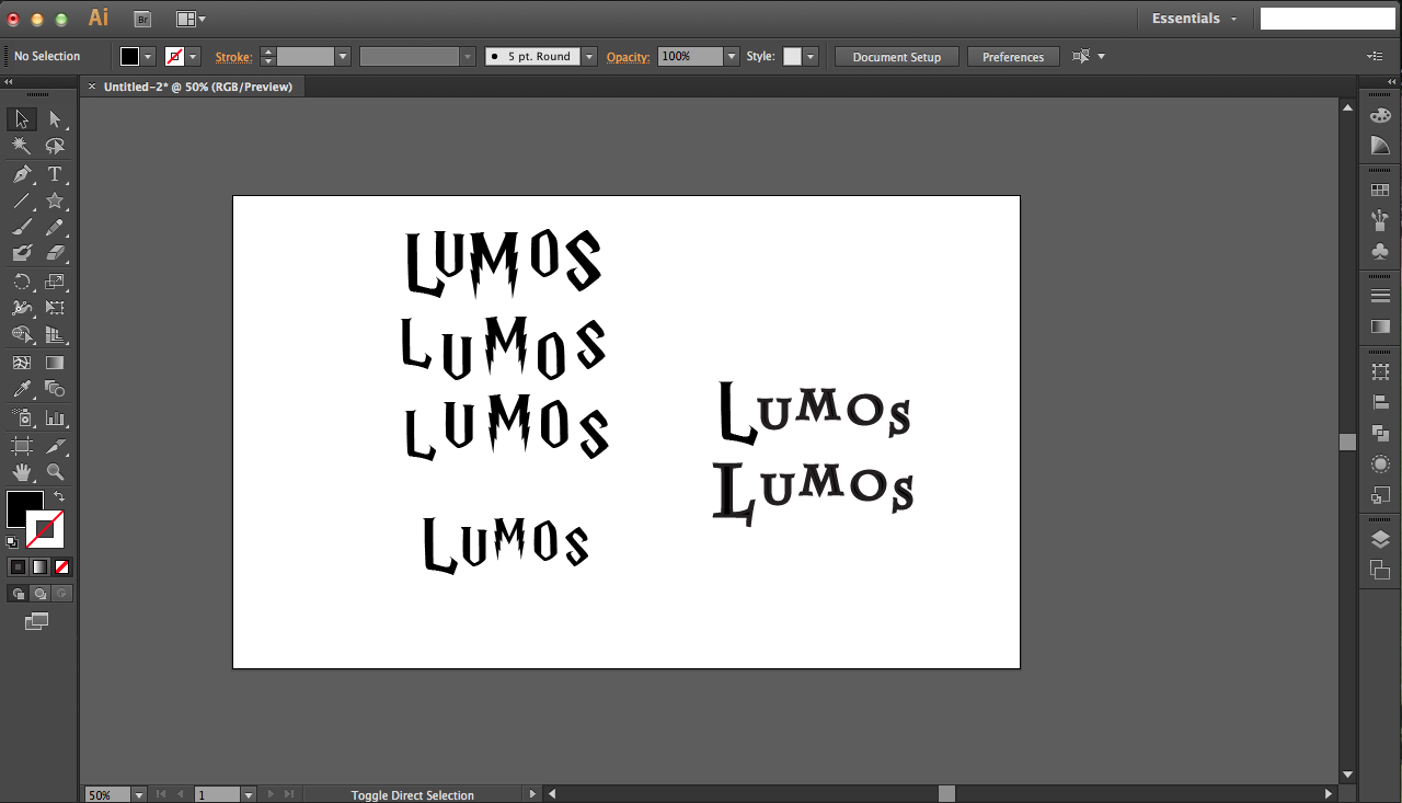
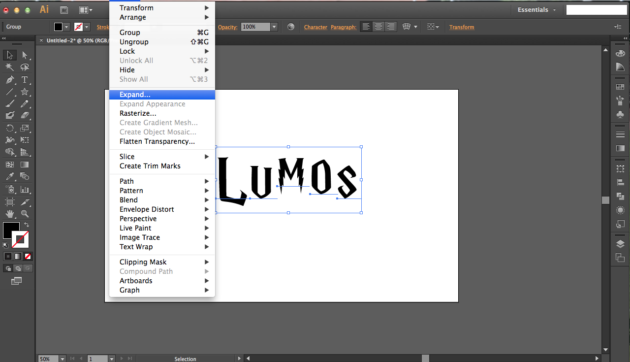
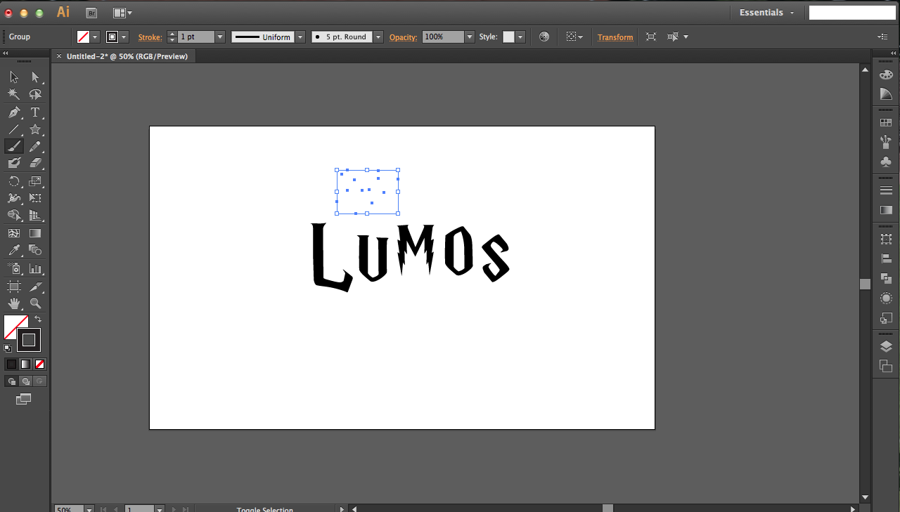
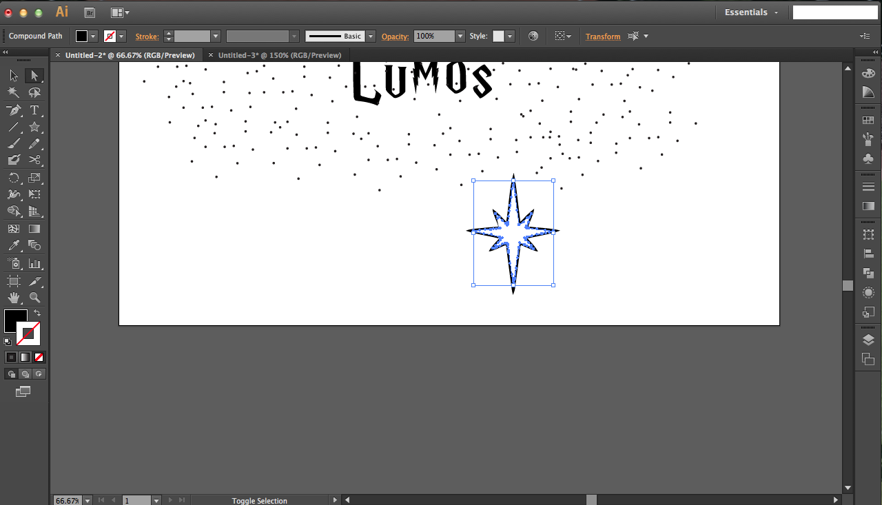
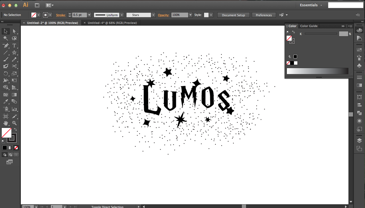
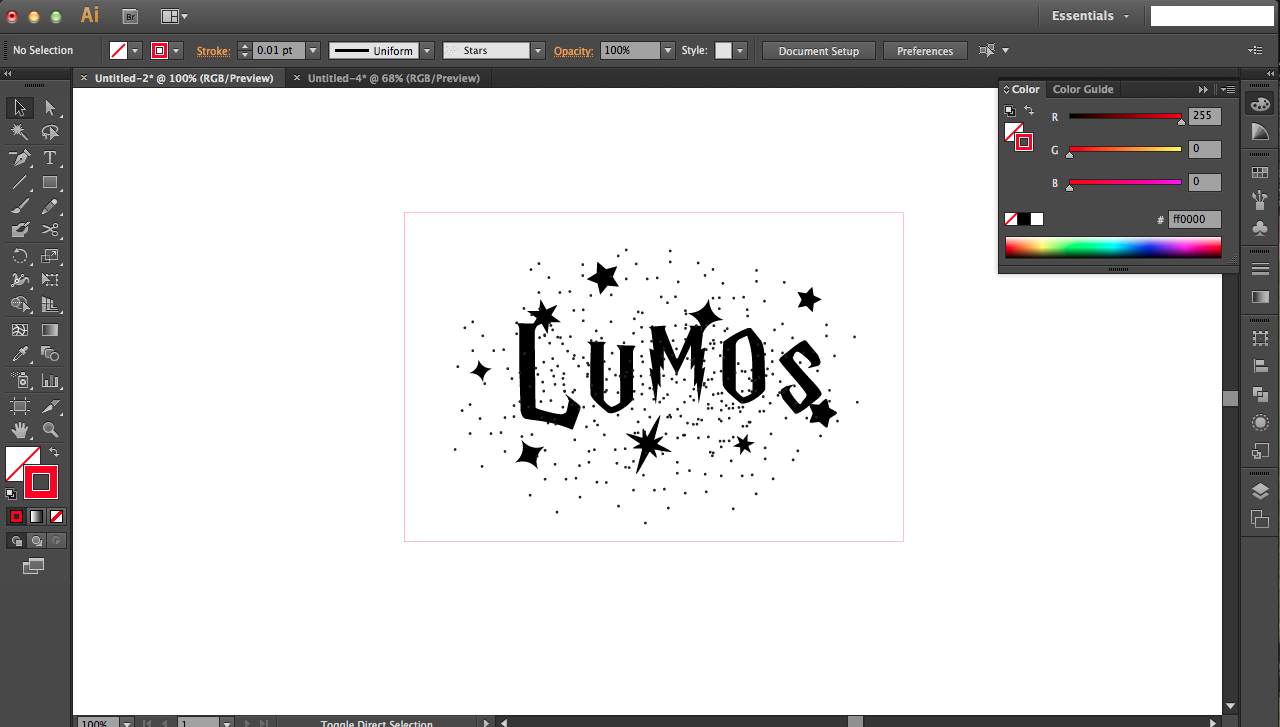
I use Adobe Illustrator as my graphic software of choice, but you may use others like Inkscape and CorelDraw as well. In any case, I'll guide you on how I made my design.
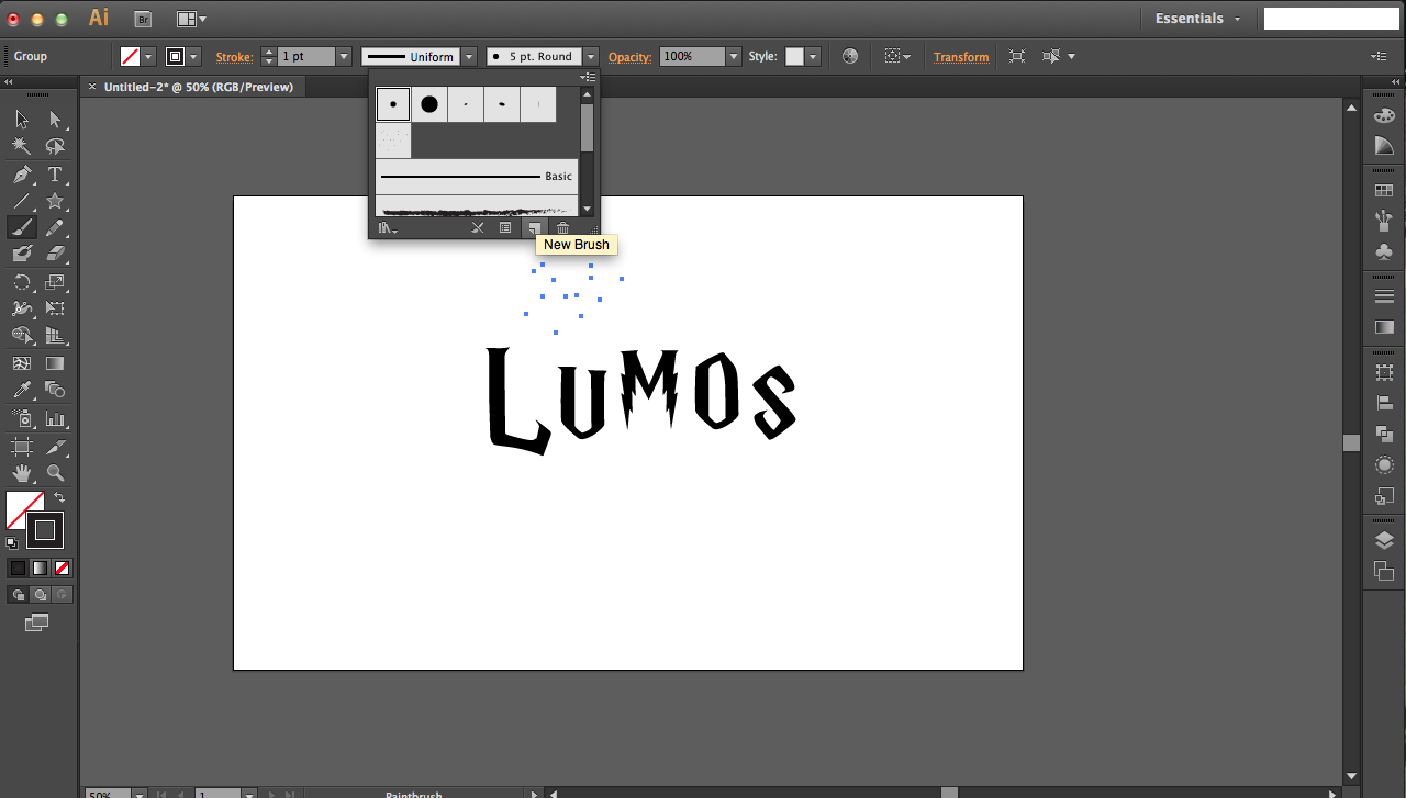
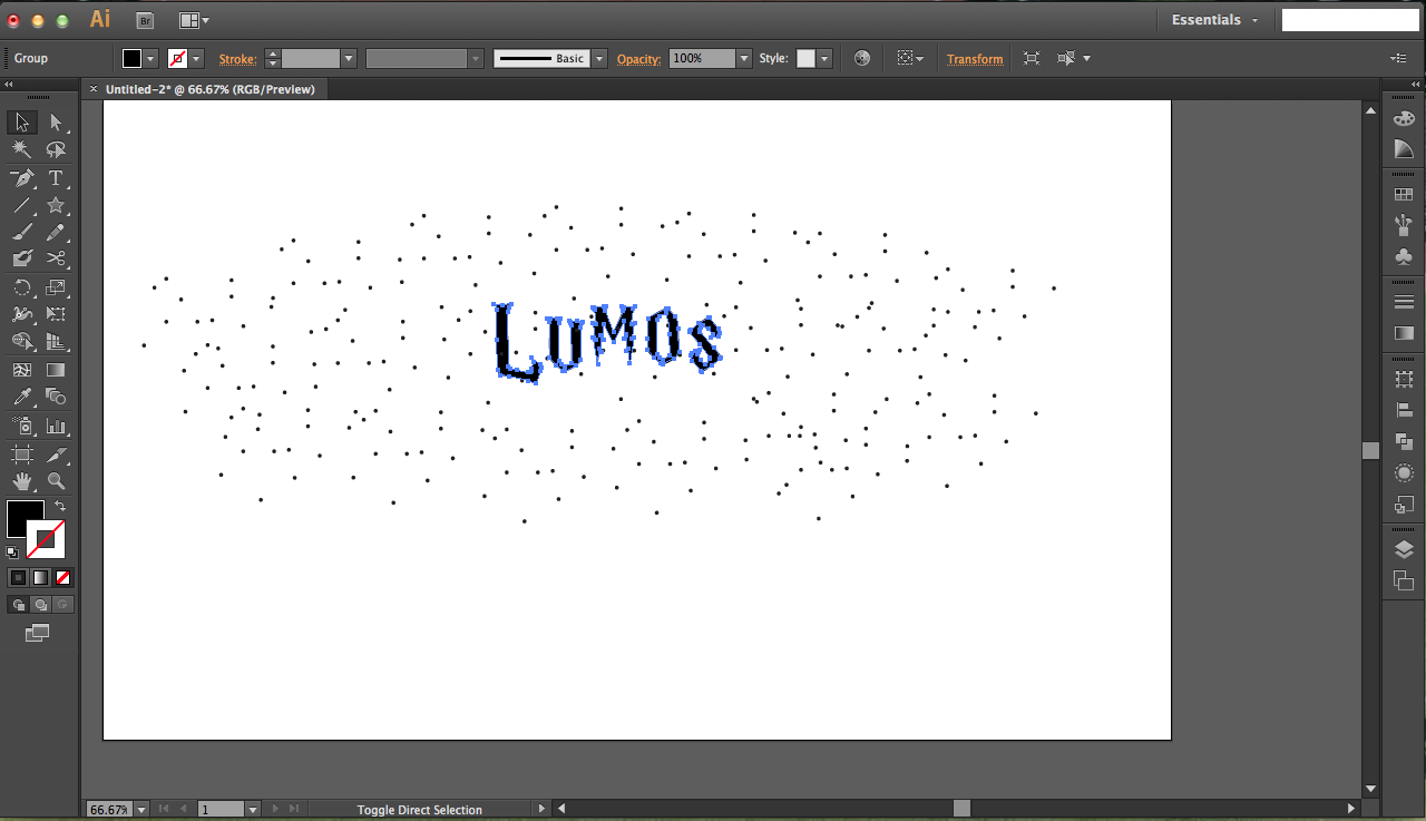
Begin by downloading the Harry P font (or any other HP-themed font you like) and typing out "LUMOS." Press ctrl/command + T in order to get this text edit tool bar: change the spacing of the letters (bottom right option) or other things to get your perfect look. I decided that I wanted to manually rearrange my letters, so I cut and pasted them into separate text boxes. Using some guidelines, I arranged the letters individually with the black arrow tool (in the top left). All up to you, really. I like to expand my text into paths, though it isn't really necessary -- I just do this in case I want to edit anchor points later. Go to the top menu bar: image > expand while the text is selected.
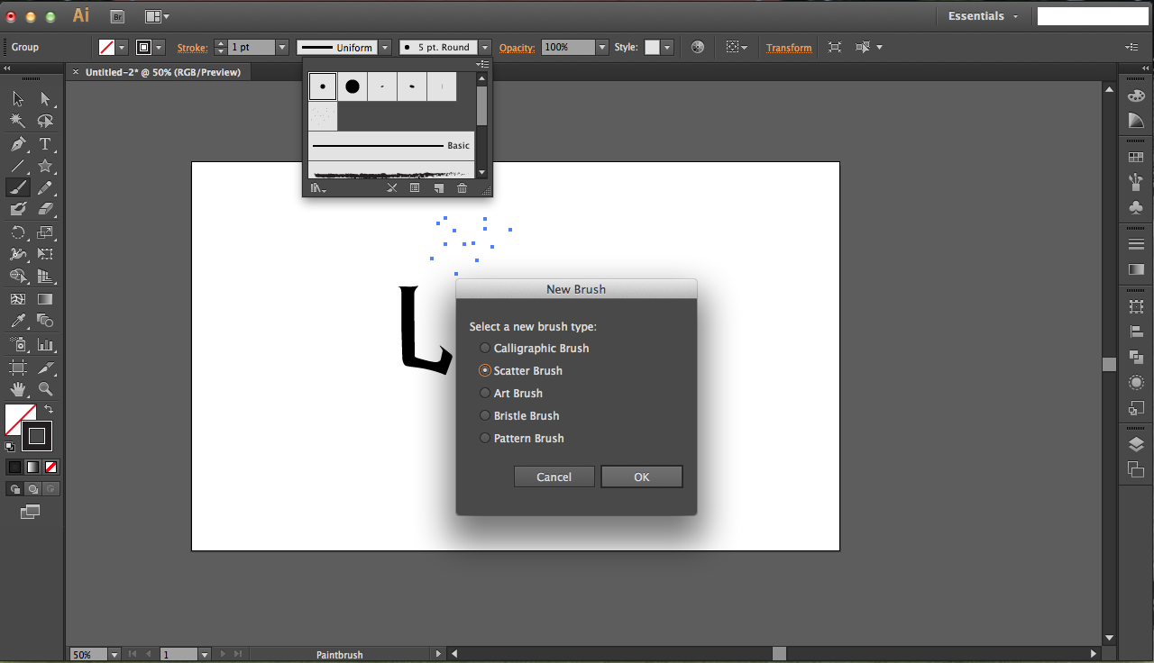
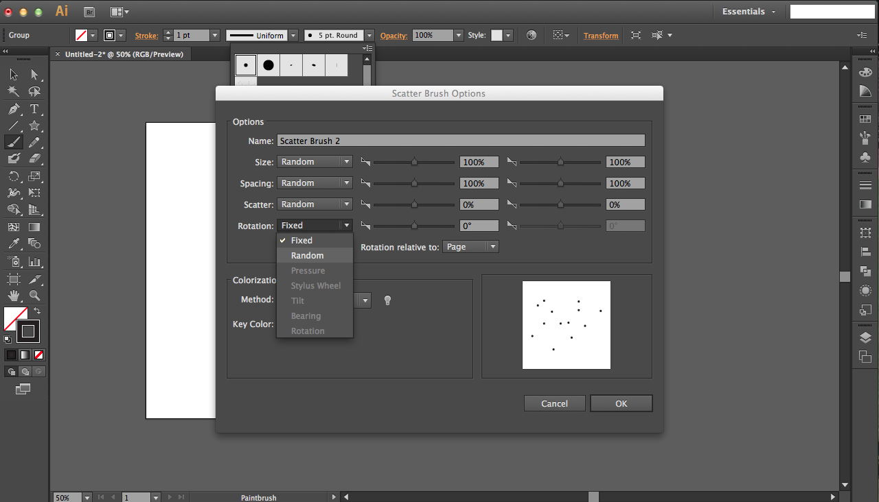
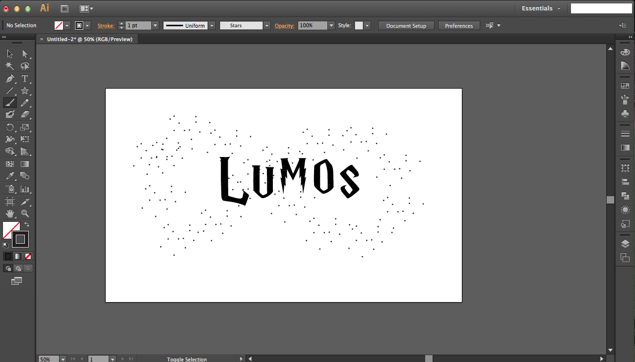
To create the splatter of stars in the background, I created my own scatter brush. Begin by using the brush tool on the left to randomly create dots. With all the dots selected, go up to the top brush menu bar and click on the brush option drop down menu. Click the new brush option, and then click scatter brush next. You'll see a lot of options; feel free to play around, but I just chose random for all size, spacing, scatter, and rotation so everything will be completely randomly generated. Now use this new brush to paint your scattered star design!
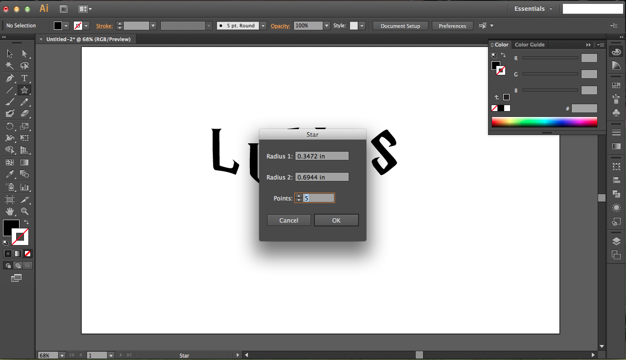
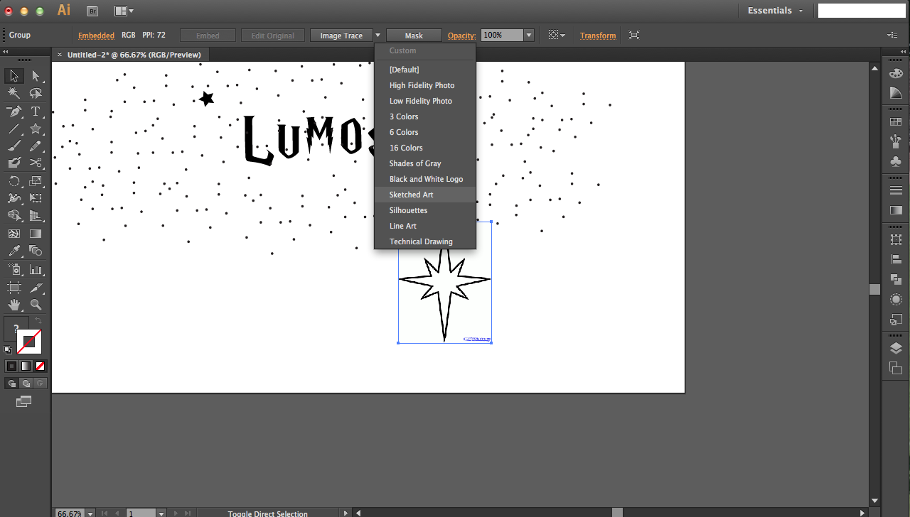
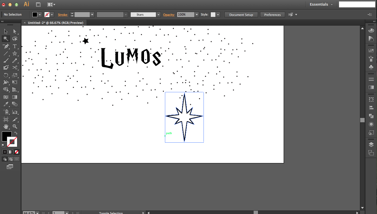
I used the star tool (click and hold the rectangle tool on the left to reveal the star tool) to make the surrounding star shapes. You can change the number of points, radii, etc. I also imported extra stars from internet images. I just pasted them in before going to image trace at the top and sketched art as my trace option. Click expand when tracing is done, and use the magic wand tool on the left to click any of the white regions and delete (only have the black paths remaining). Since I wanted this star to be filled in, I used the white arrow tool on the top left to select the inner path of the star as shown. Then I pressed delete to get rid of it.
When you're happy with all your stars and such, add a rectangle for cutting out the design. It should be pure RGB red, at 0.01 pt thickness.
Case

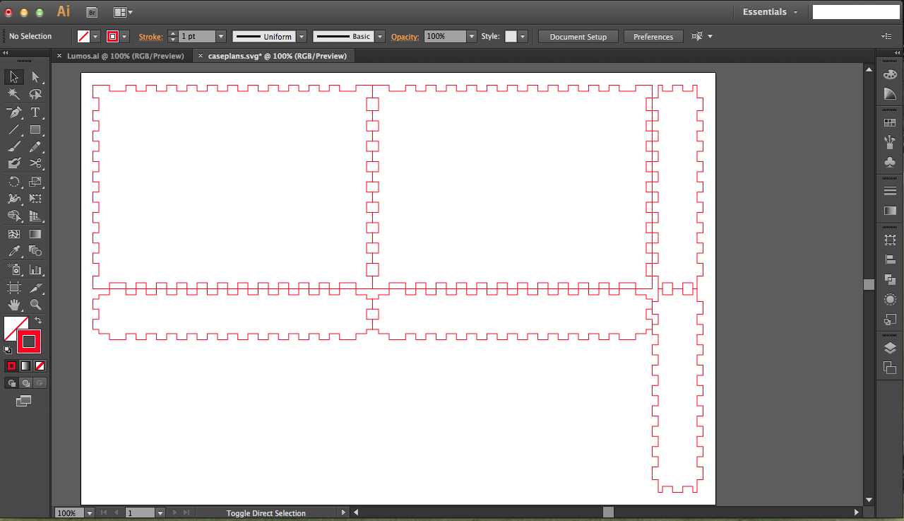
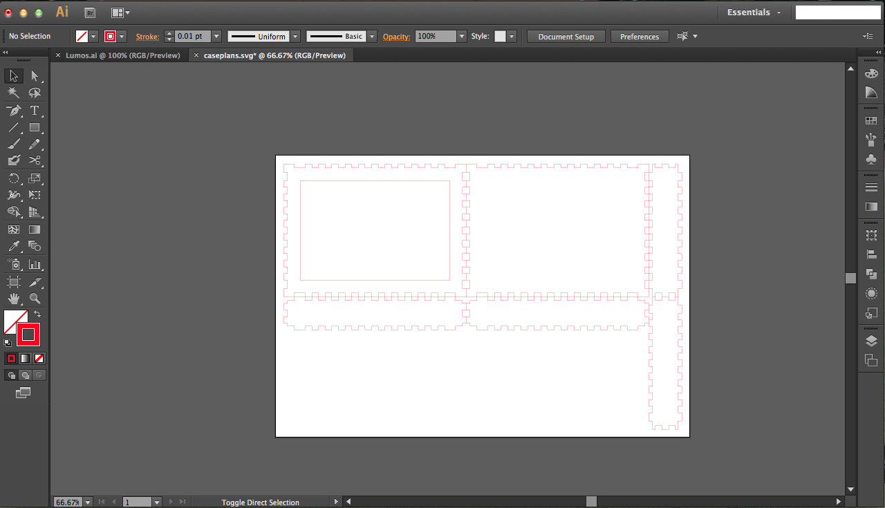
For the box of the nightlight, I used makercase.com to generate the plans. The height was 4", width 5.5", and depth 1" to accommodate 1" margins for the Lumos design.
Once I got the svg file from the plans, I imported into Adobe Illustrator to add a rectangular cutout in the front panel to accommodate the Lumos veneer design (+0.25" margins so I could glue the veneer in from the back of the panel).
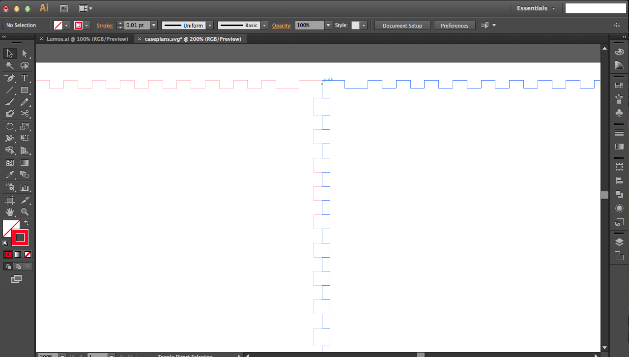
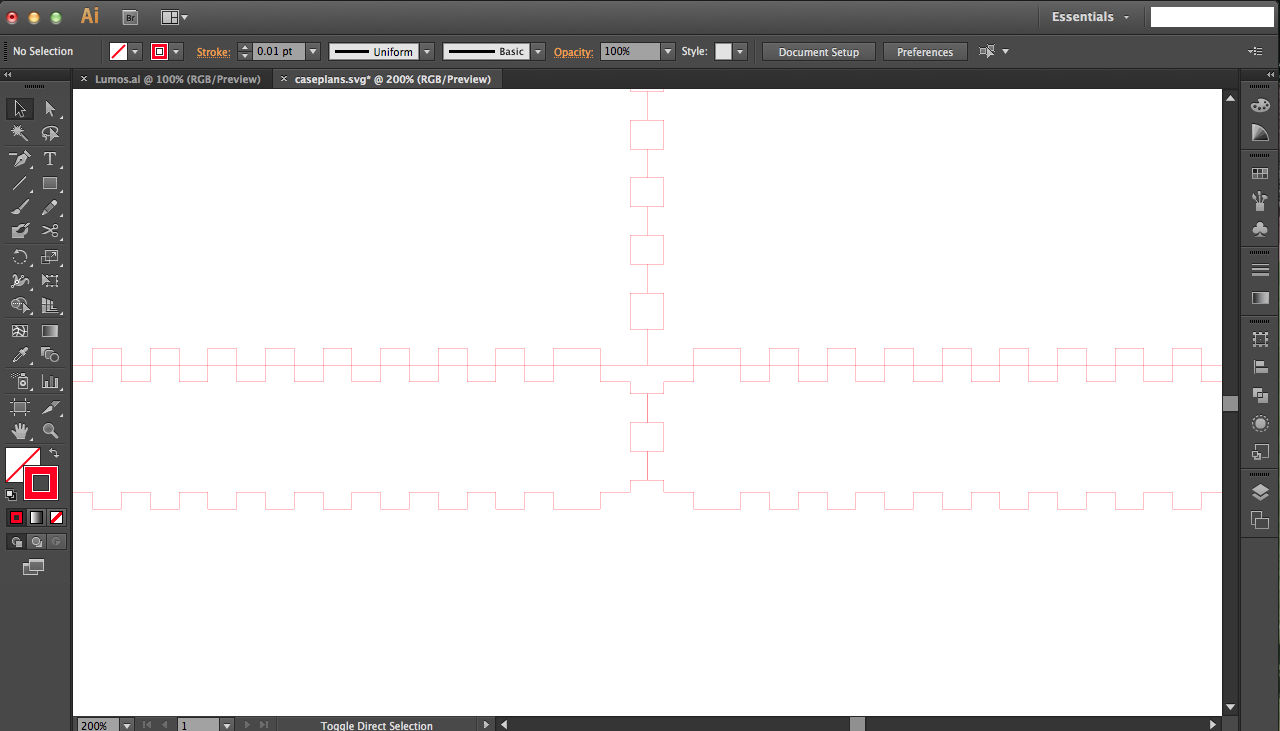
The overlapping edges look darker that the rest of the lines because because there are actually two overlapping lines. Your laser would trace that twice, which we don't want, so use the scissors tool on the left to cut the paths and delete extraneous lines.
Testing the Laser
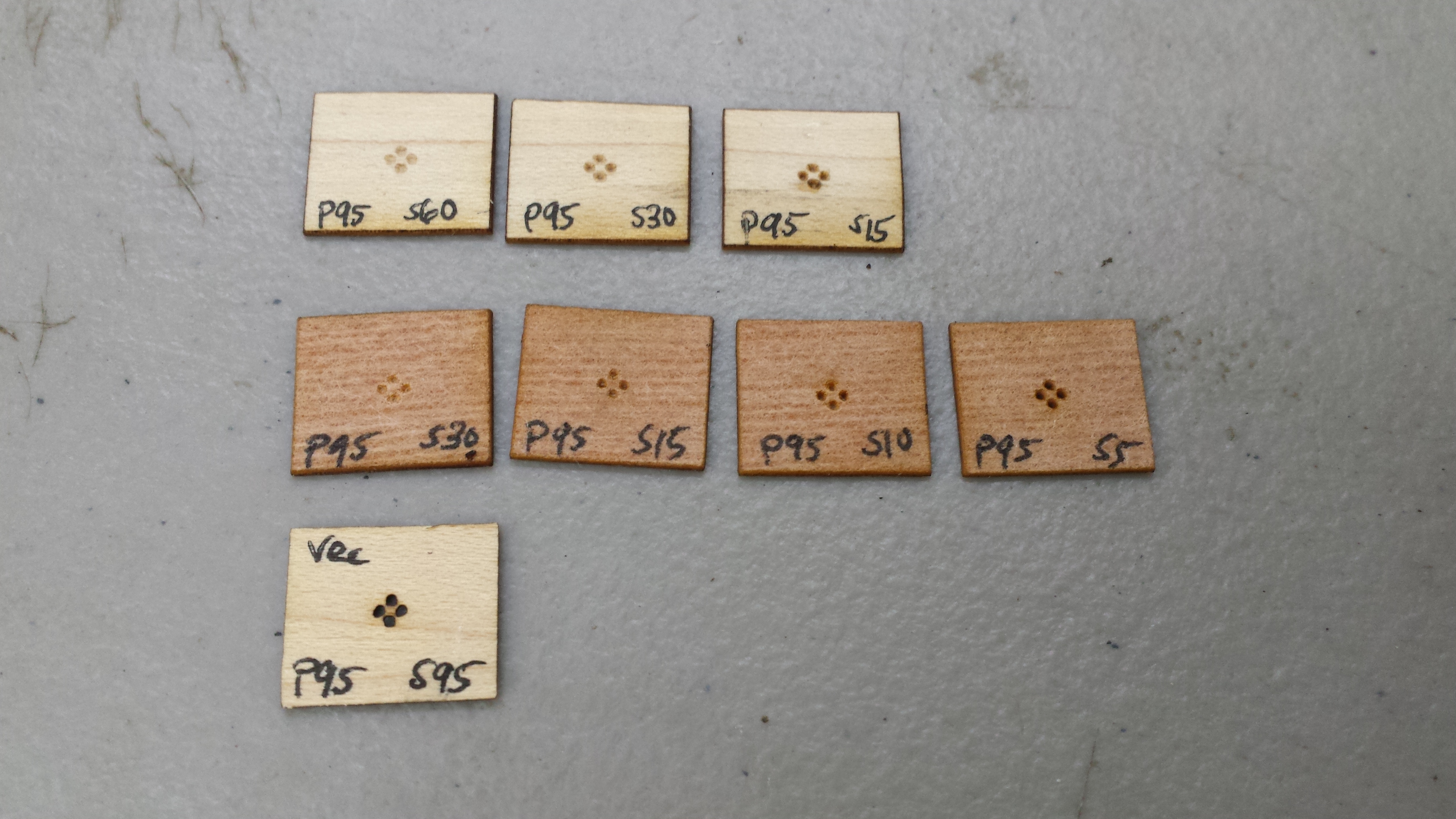
Because I had a sprinkling of stars in the background, I didn't want them to overwhelm the text. Thus, I needed them to be small, light holes that still allowed pinpricks of light through them. To do this, I tested different raster settings on the laser to see what settings I should use to get those holes (and perfectly cut the veneer with minimal scorch marks).
I found out that I liked the effect from raster engraving the holes on the back of the veneer to minimize scorch marks around the holes, and that's what I eventually went with.
Laser Cutting
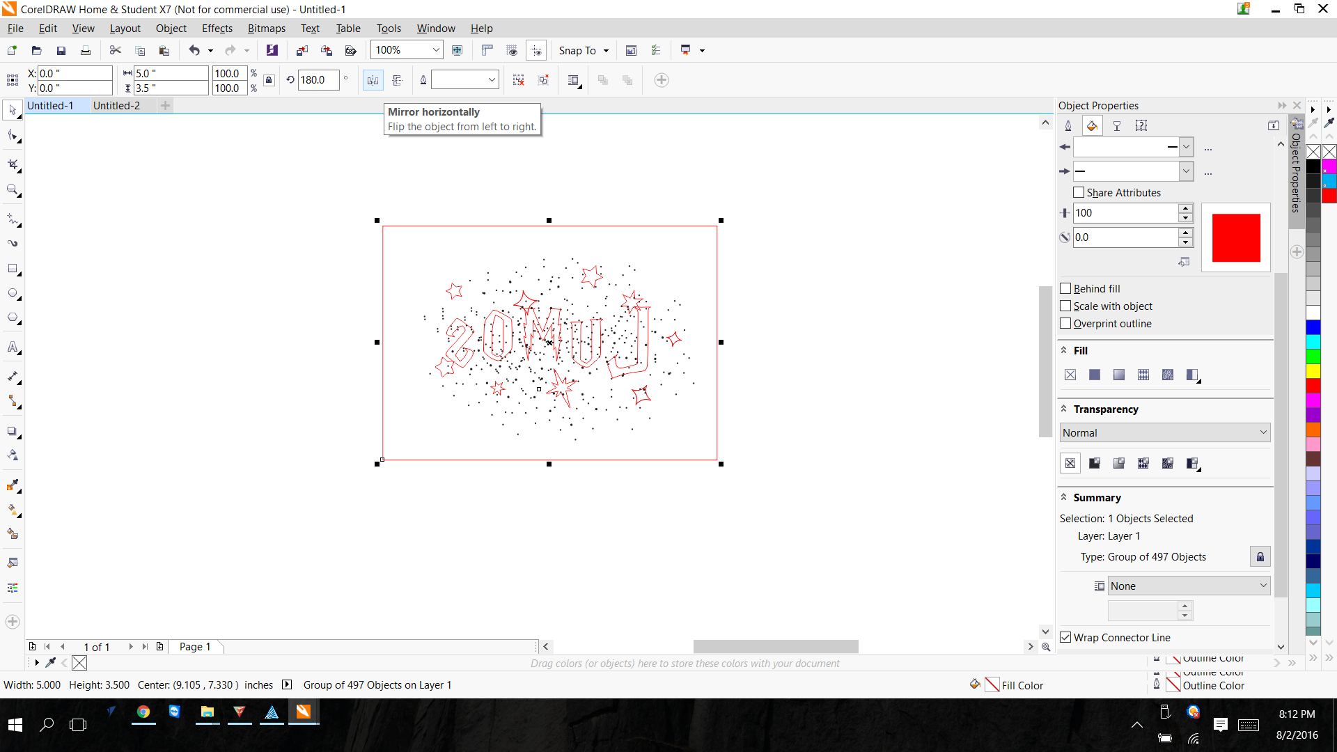
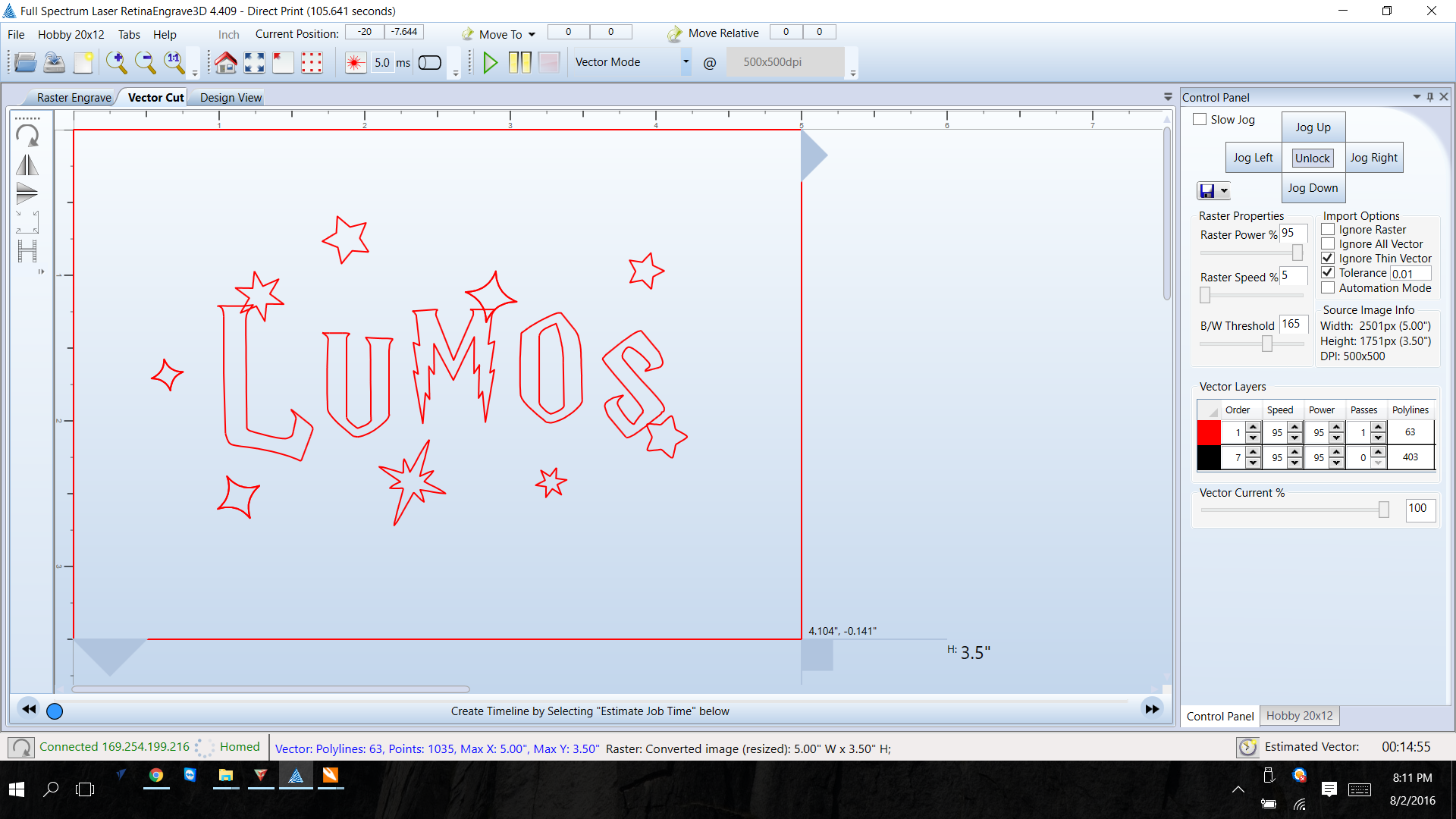
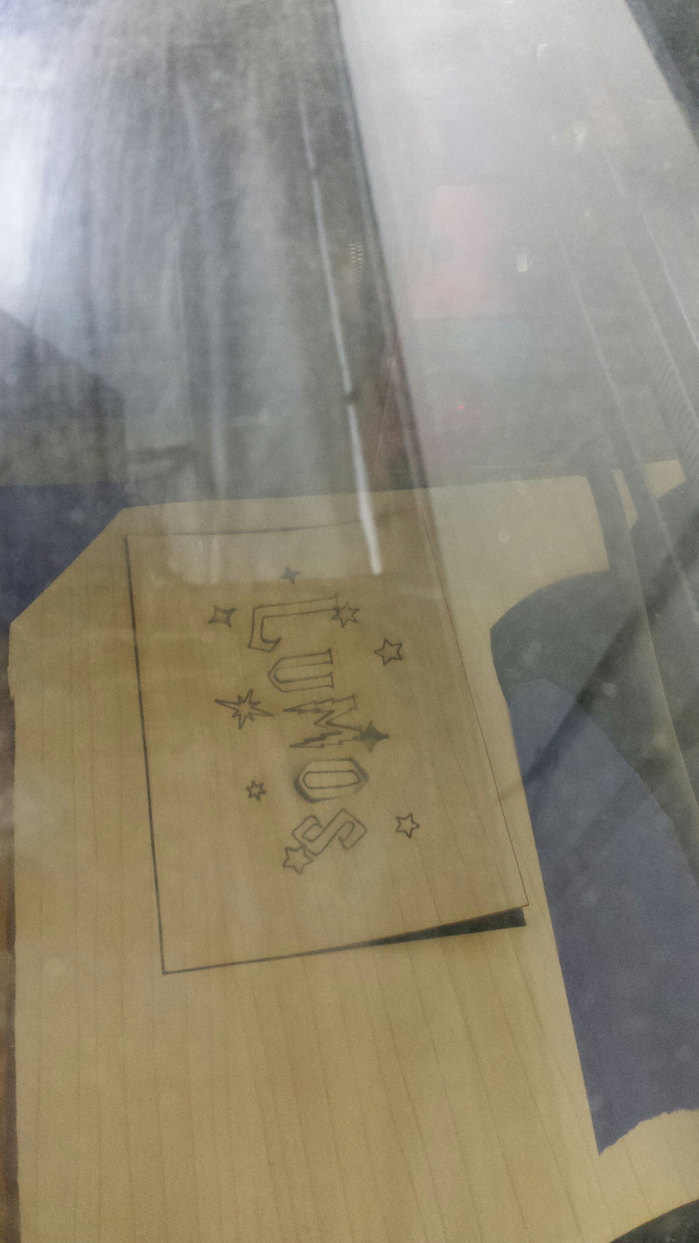
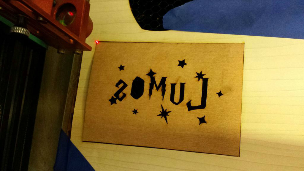
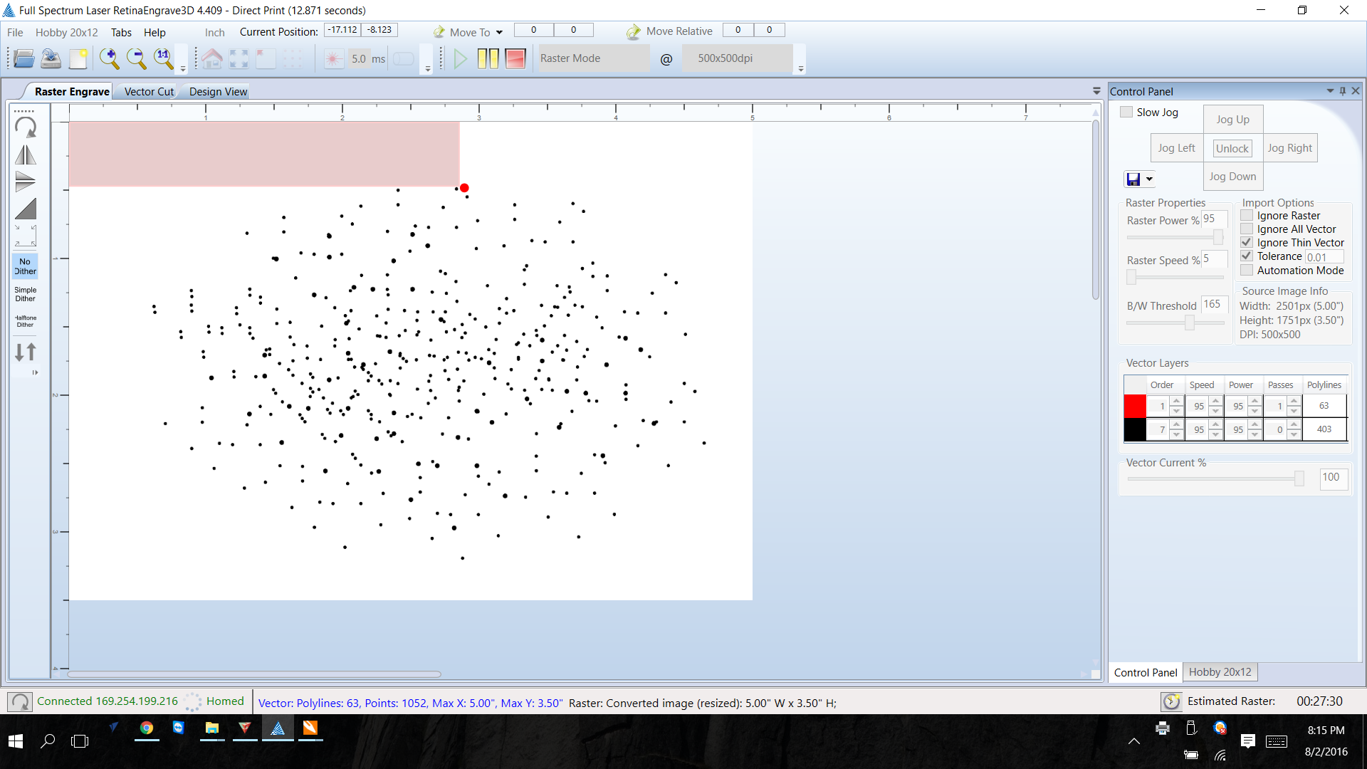
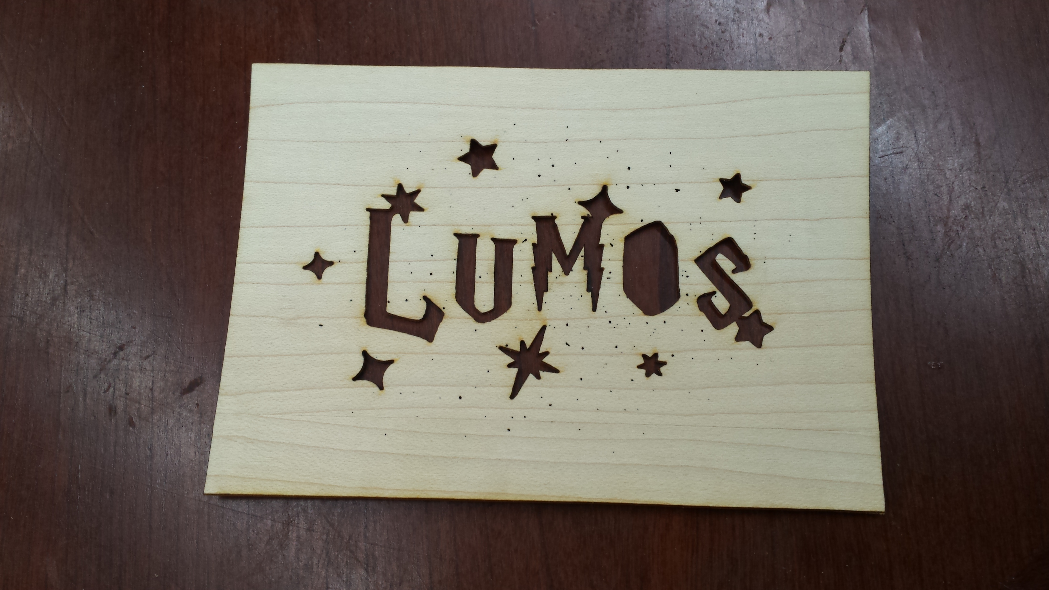
Send the files over to your laser cutter to print. You'll need a separate mirror file of the veneer image for rastering because the raster is on the flipped side of the veneer. SO: use the regular file to cut out the lumps + stars, flip it in the laser (keep the same position in the laser though!), and use the mirrored image to raster the sprinkled stars from scatter brush.
My raster setting was power 95% speed 5% and cutting was 95% power 95% speed.
Not shown here but do cut your frame for the Lumos design too. I did that on 1/8" birch before I stained it in dark walnut.
I forgot pictures of this, but for assembly of the box, glue the back panel and all four side panels together, but NOT the front piece. This is because I wanted to keep it easy to open for battery replacement still. Don't forget to glue paper on the back of the Lumos design (and add the little piece of the O that gets cut out) to aid in diffusion of light.
Cutting Leather for LED Strip


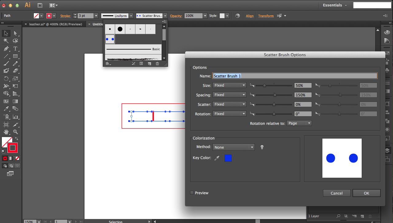

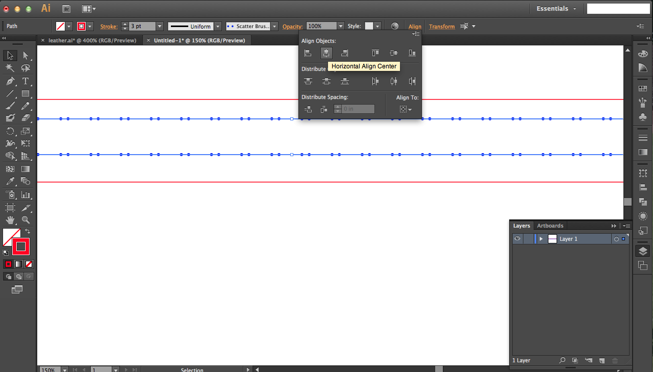
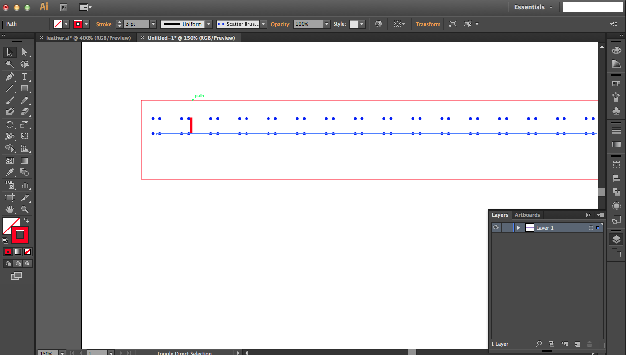
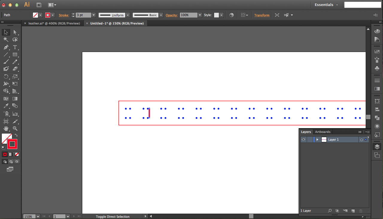

You can use a regular LED strip light but I used homemade LED strips since I didn't have regular ones on me. To do this, I sewed LEDs to a leather strip.
My leather was pretty thick so I designed a file to cut on the laser with pre-cut holes for stitching (so I get perfectly aligned LEDs). Start with a rectangle with the dimensions you want for your strip (measure what fits in your box design, for me it was 17x1 inch). Then draw a line across the top of your rectangle, and create another scatter brush (consisting of two horizontally-aligned dots this time) as your line's pattern. Repeat for another line below the first, and line up the centers with the align options on the top tool bar. Draw a vertical line that's the length of your LED's width so you know how spaced out your LEDs are. Then reposition your lines accordingly.
Cut on your leather with whatever power/speed works for you. I found that the holes should be rastered at 95% power and 1% speed (I really need to change them to vector cuts, but for now it's fine) and cutting should be done at 95% power and 30% speed on a 40W laser. But that's for my leather! Might be different for yours.
Homemade LED Sequins, and Sewing
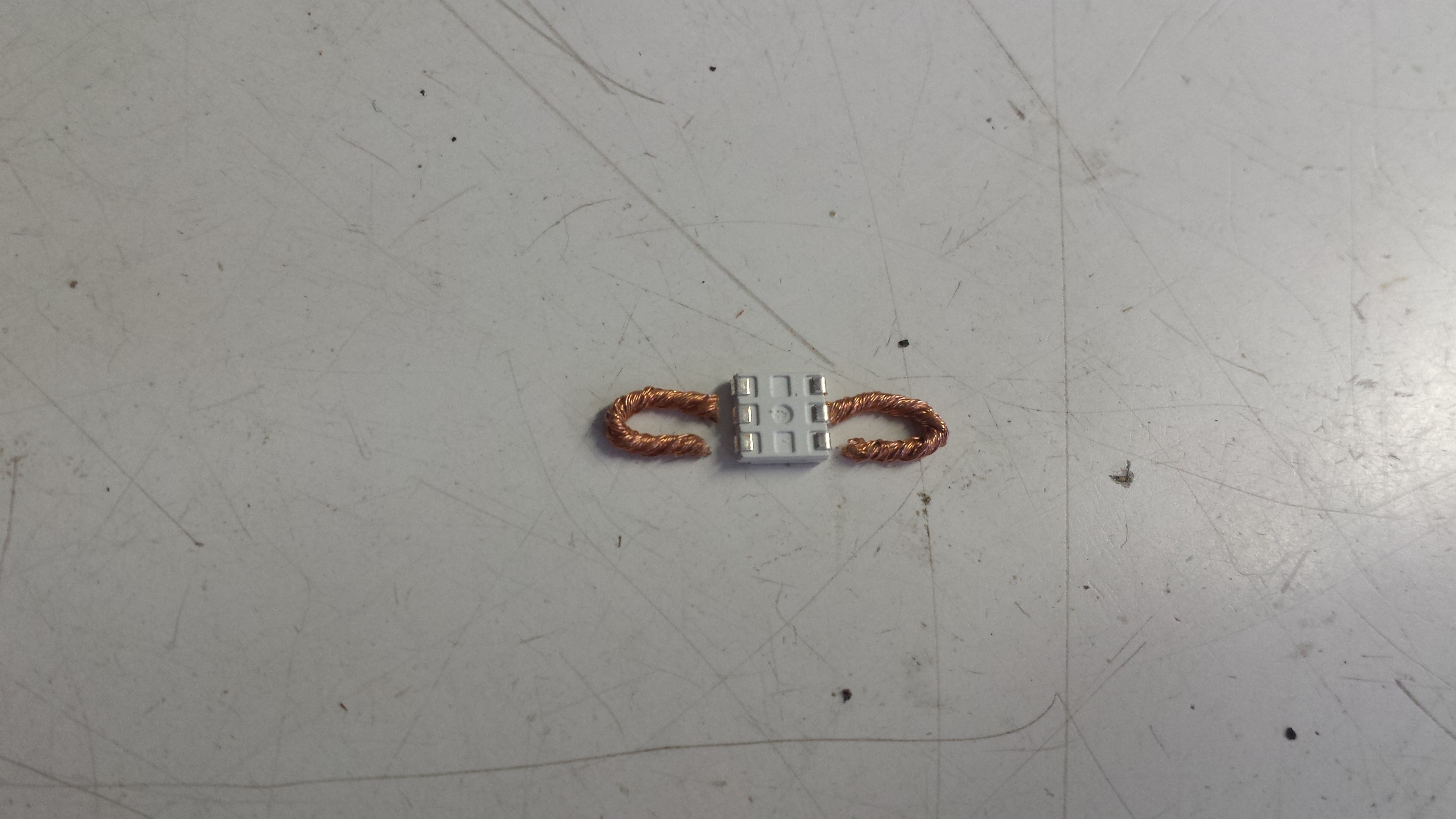
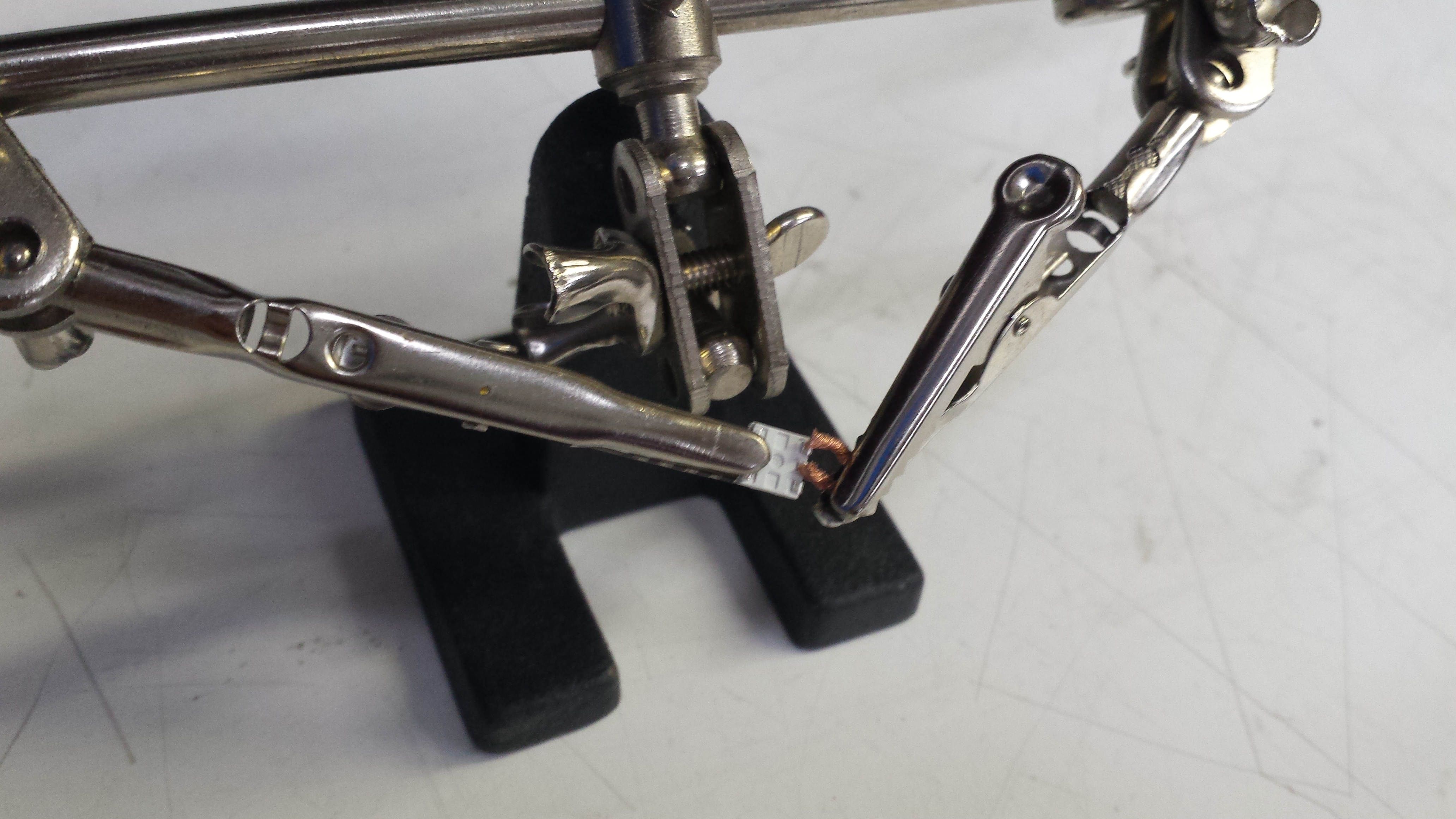
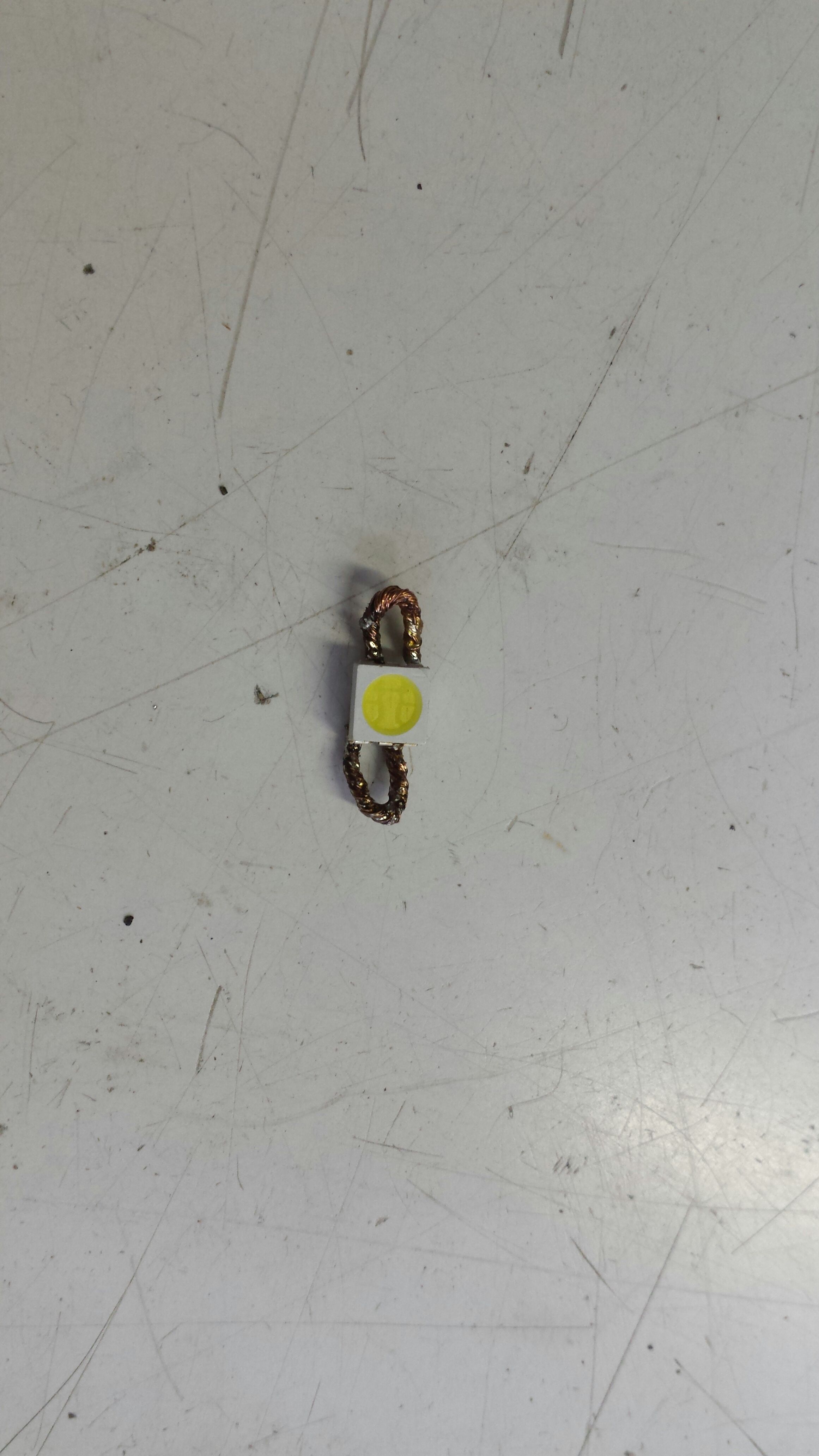
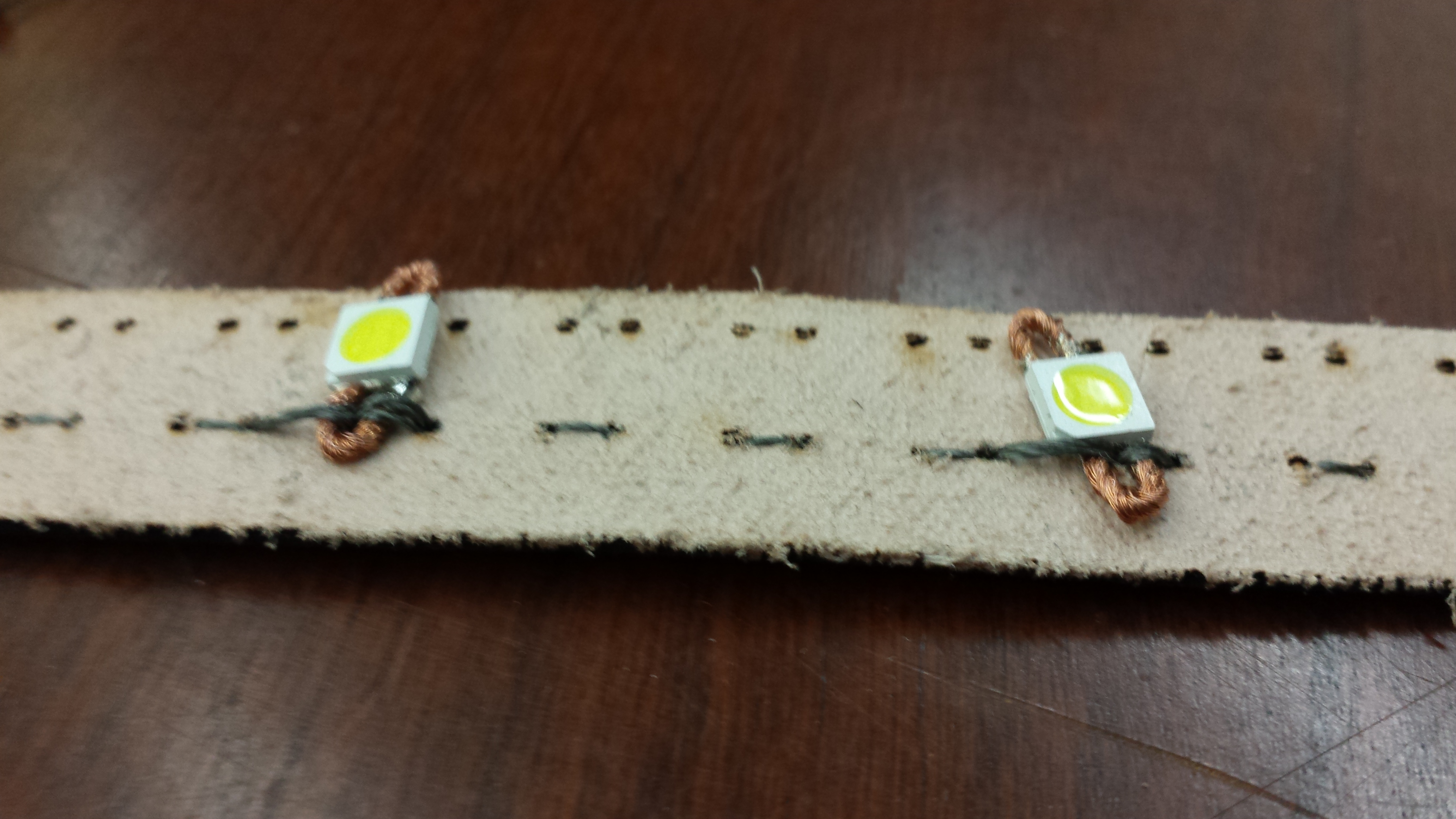
Each homemade LED sequin has one 5050 surface mount LED and two loops of solder wick soldered on the metal pads on the back side of the LED.
Position the solder wick loops on the backside of an LED and solder them on either side. Use minimal solder. Helping hands really help. Be sure that they face the correct way! All positive terminals of the LEDs should face one side, and the negatives should be aligned and facing the other side. You're basically hooking up all LEDs in parallel.
Then just hand stitch the LED sequins to your leather strip. Be sure to pull the conductive thread tight as you go along; loose stitches make for an unreliable circuit! Tack down the sequins securely by looping through the hoops multiple times. I used about 10 total LEDs, but be careful about using more: more will drain your battery quicker.
IR Circuit
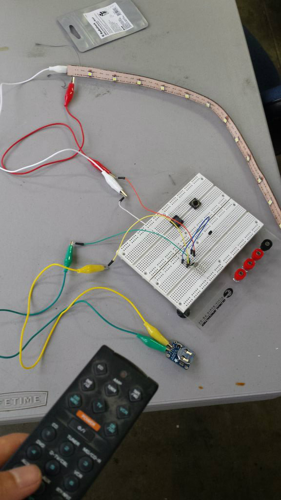
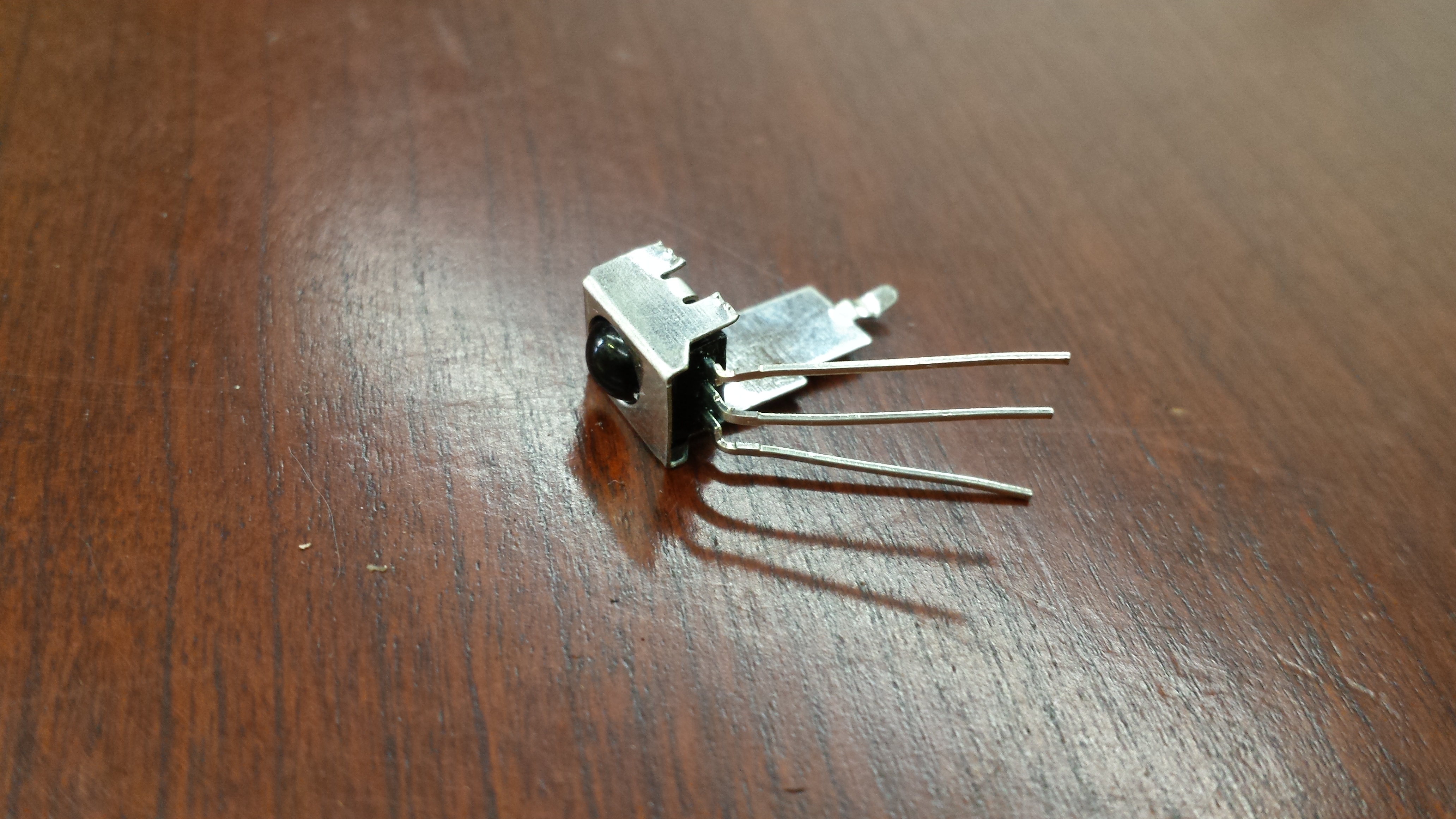
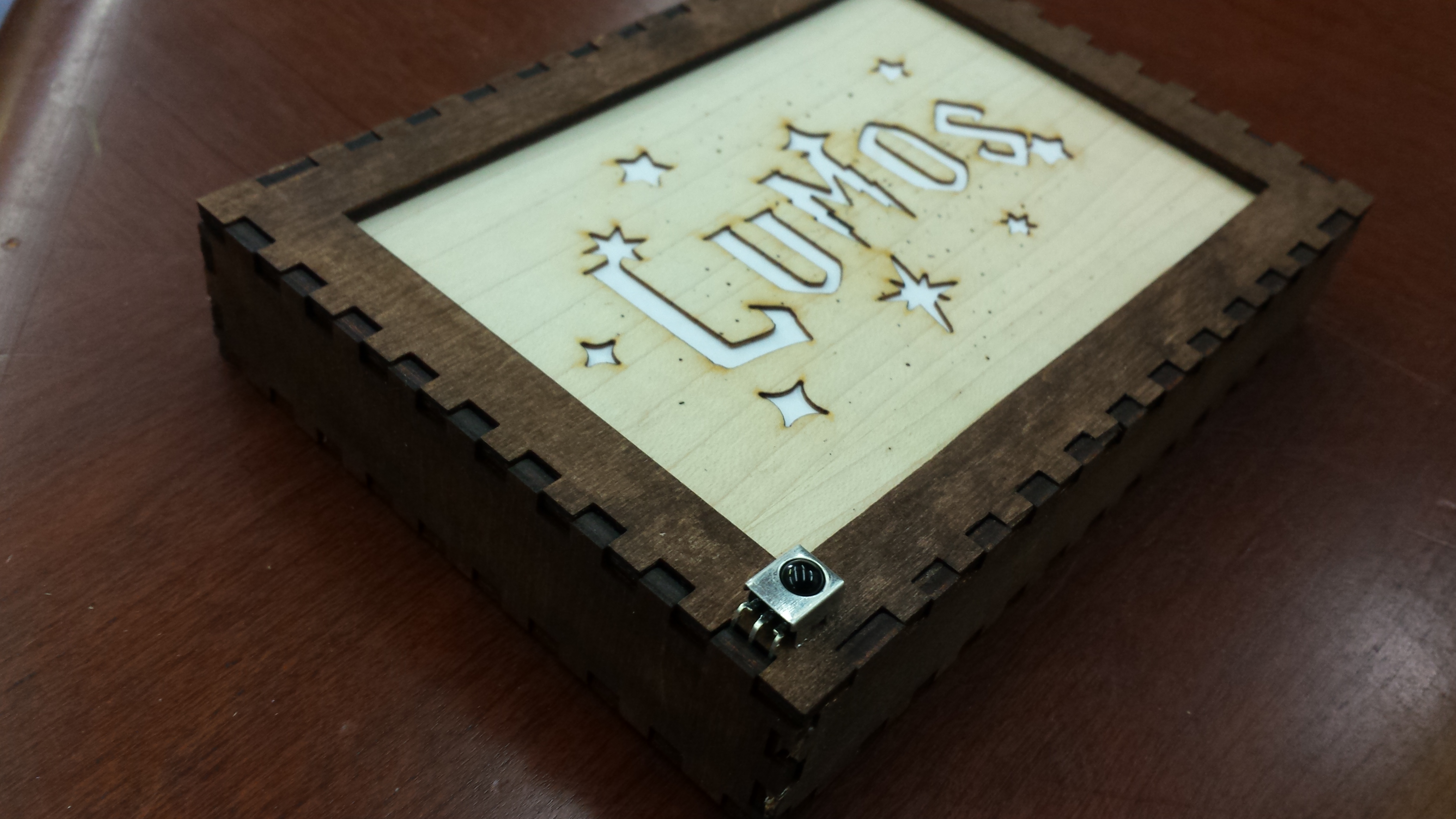
See this adafruit page on a great explanation on the sensor (mine is from RadioShack but the concept is the same). My first image above has notes on where all the terminals lead to.
My IR sensor had three pins: left-most (with IR bulb facing upward) was output voltage, middle was supply ground, and right-most was supply voltage. This means that the positive terminal of my power source (3V battery) was connected to the right-most pin and the negative terminal was connected to the middle. I connected the negative terminal of my LED strip to the left-most pin and the positive terminal to the right-most pin (yes, this means that two wires are connected to the right-most pin).
You might be wondering: no resister?? What if your LEDs get burnt out? Well, I relied on the intrinsic resistance of my sewn circuit: the conductive thread has resistance of its own, and since my strip is quite long the resistance is low but works for my circuit (~10 ohms per foot, and I used about 2-3 feet).
Naive? Perhaps.
But am I selling this as a product and worried about perfection? Not really.
If you are worried though, simply hook up a resistor (330 ohm or lower should do) to a terminal of your led strip.
To troubleshoot, make sure your terminals are all hooked up correctly as described above. Use a multimeter to see where your circuit stops making sense (voltage is where is should be in the right direction, etc.). You might also want to check your TV remote in case: hold it under your phone camera and it should be blinking as you press buttons.
Trim your sensor if it has those protrusions for attachment on breadboards (see second and third pictures above). Test to see that it wraps around your light box's edge; the pins should be sticking inside the box. The reason why I had my sensor out the box was because I found that it worked a lot better with my IR LED wand when it was exposed rather than hidden in the box, but this is up to you.
IR Wand
Unfortunately I don't have good pictures of this step, but I essentially followed directions from this tutorial that goes over how to hide an LED inside a wand. Instead of a LED emitting in the visible light spectrum, I used a 5mm infrared LED. Also instead of the flip switch at the bottom, I attached a button switch to the side where my thumb contacts the wand (so I can easily turn the LED on and off from the side).
You might be asking: doesn't the sensor work with 38kHz frequency for pulsing IR LEDs? Why would putting an IR LED on a wand and turning the LED on work with the sensor?
Well, I was experimenting with my LED + sensor and discovered that the IR LED's proximity actually resonates with the sensor and manages to turn on the LEDs. My quick and dirty theory is that the proximity of the LED amplifies the noise that the sensor picks up somehow, but in any case holding the LED close to the sensor worked. Of course a TV remote works better though.
If you want your LED to work more effectively and be modulated with the correct PWM, you could hook it up to a microcontroller (but then your wand would be huge and then might as well use a broken TV remote) or use a small PWM controller IC chip of sorts. I didn't have one on hand, but you can probably pick them up at RadioShack (if it's still open near you...)
Electronics: Preparing the Power Supply
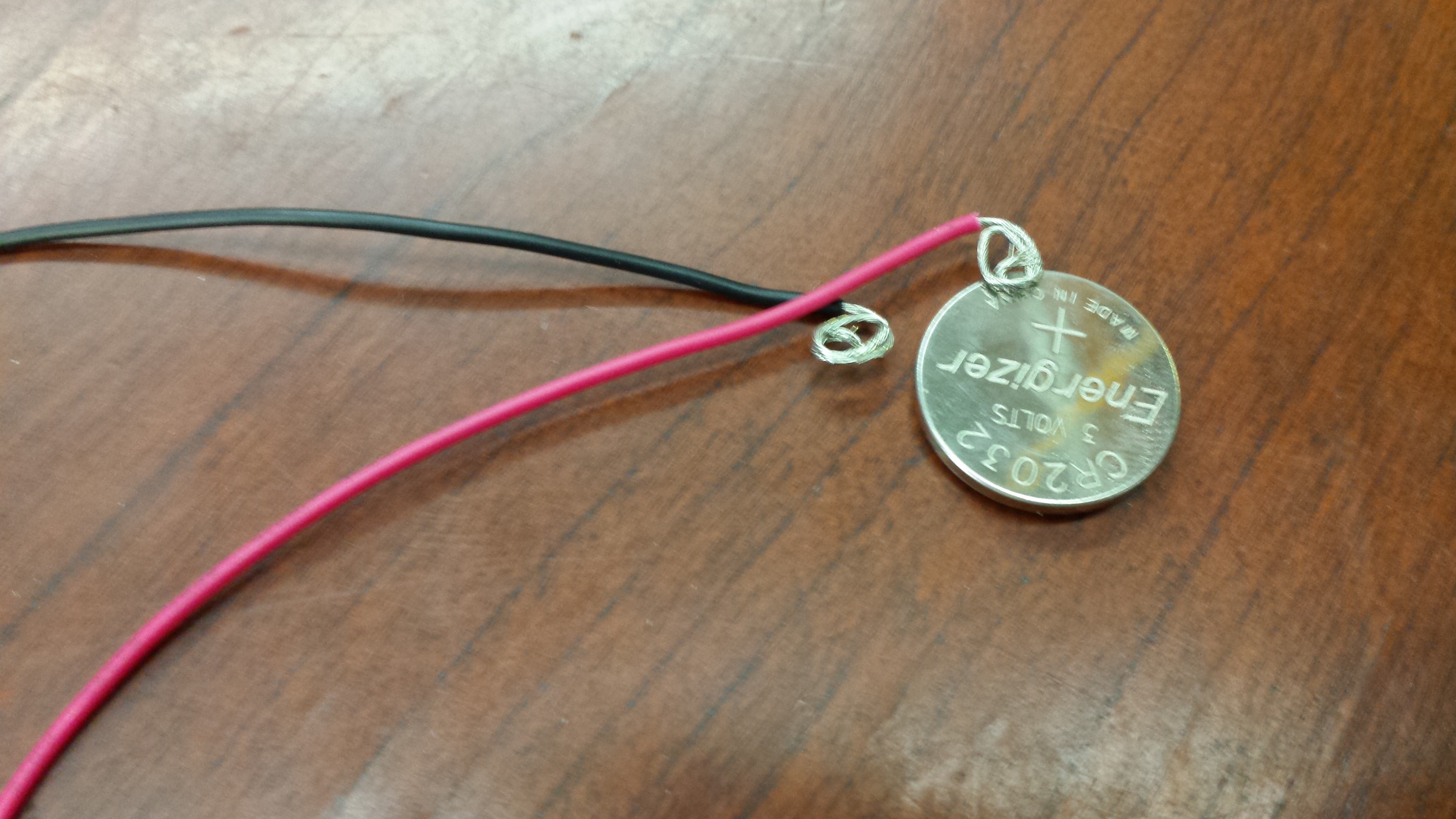
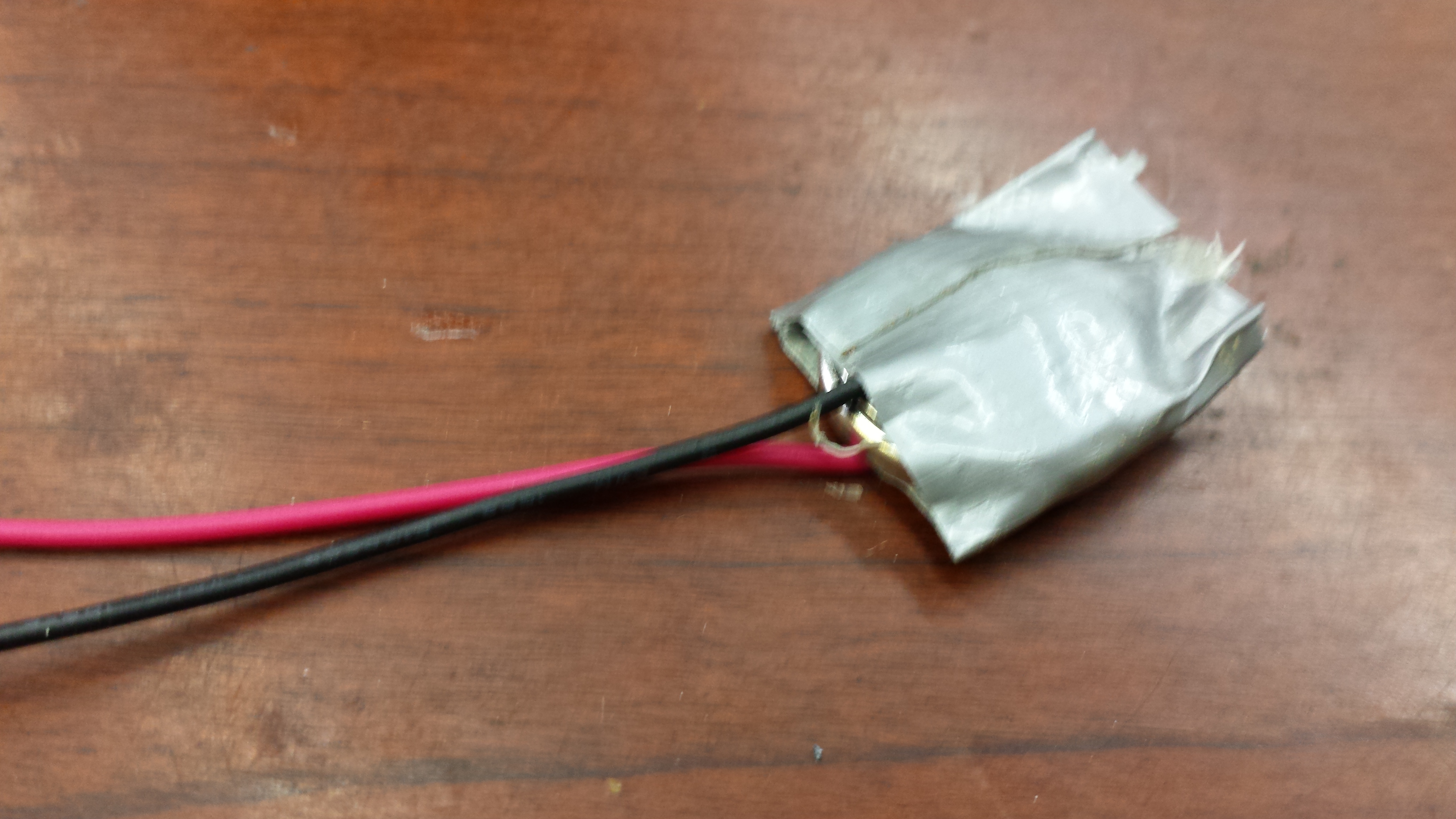
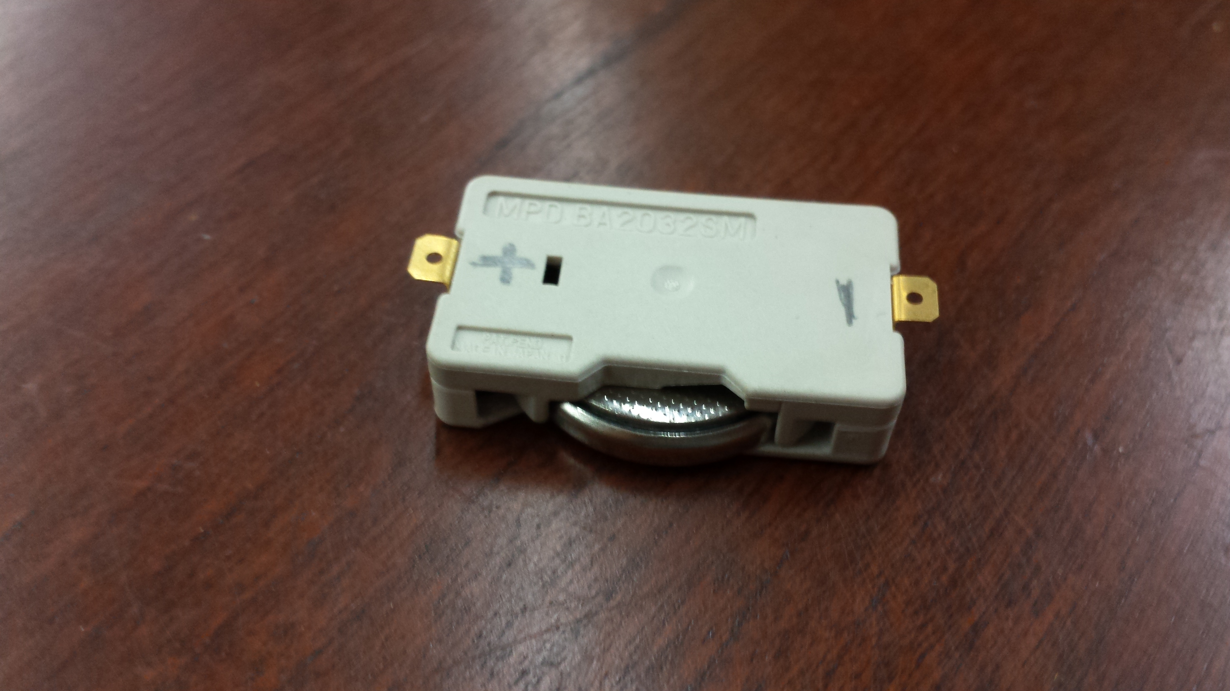
As a quick and dirty way to attach wires to the positive and negative terminals of my 3V battery, I simply curled up the ends of two plastic coated wires and taped them on either side of the battery. I later wanted to implement some batty holder of sorts (I had the sewable one in the third picture above on hand) in order to more easily switch out batteries, instead of the *ahem* resourceful tape method.
Not picture above, but don't forget to attach these wires to the correct pins of your IR sensor (positive side of battery to supply voltage pin, negative side to ground pin).
Connecting IR Sensor to LED Strip
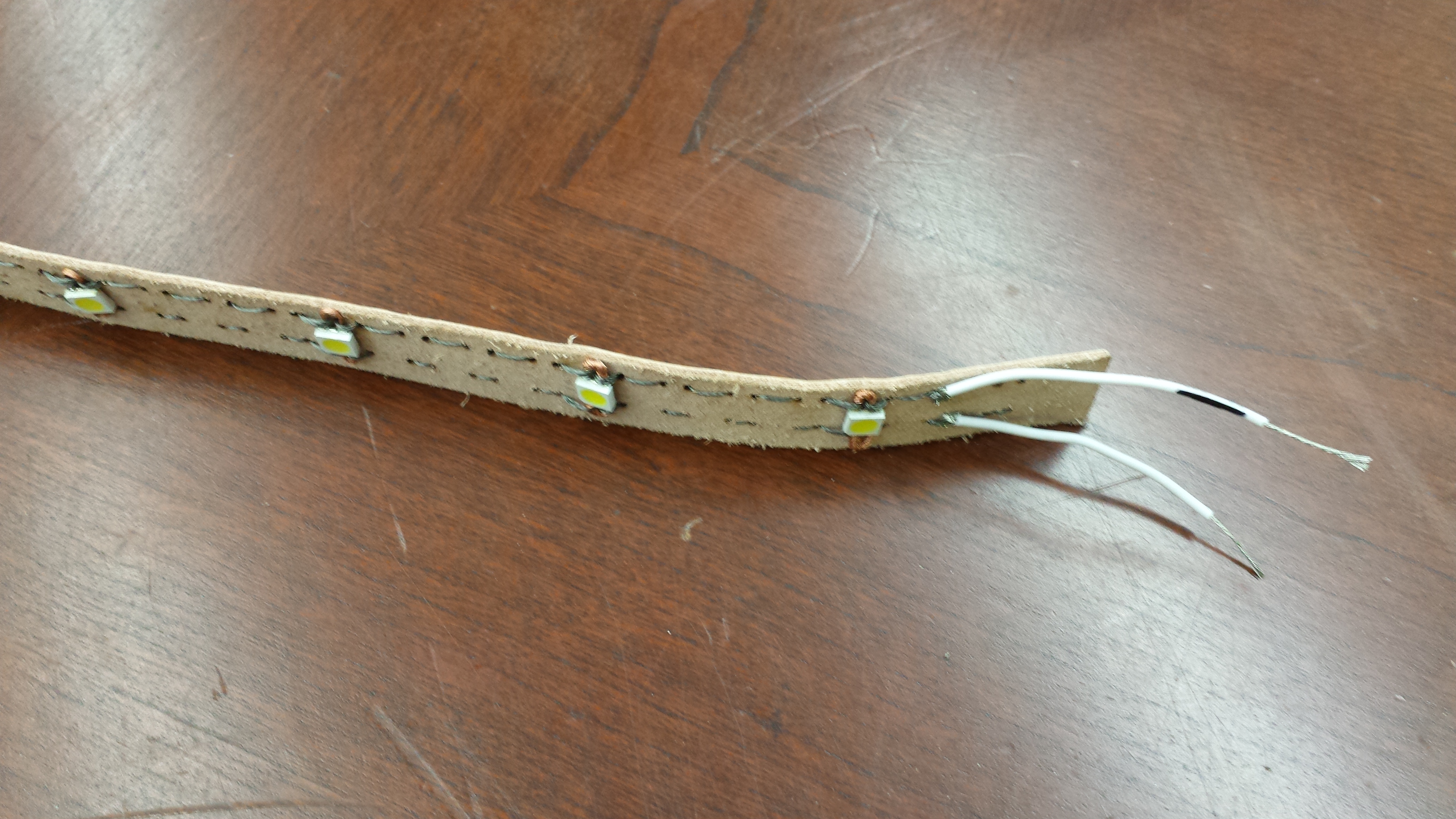
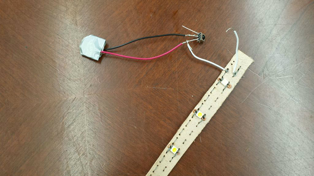
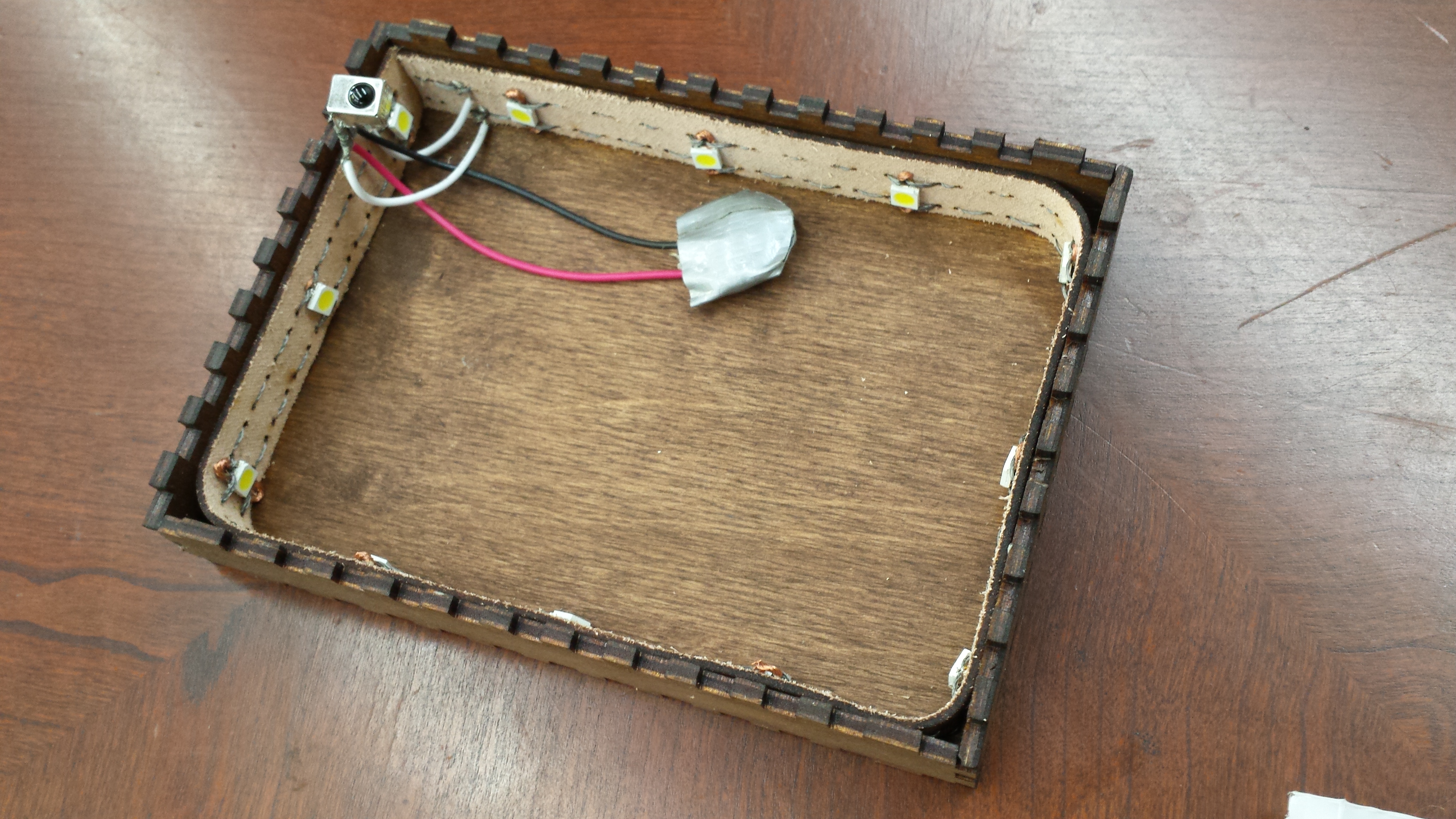
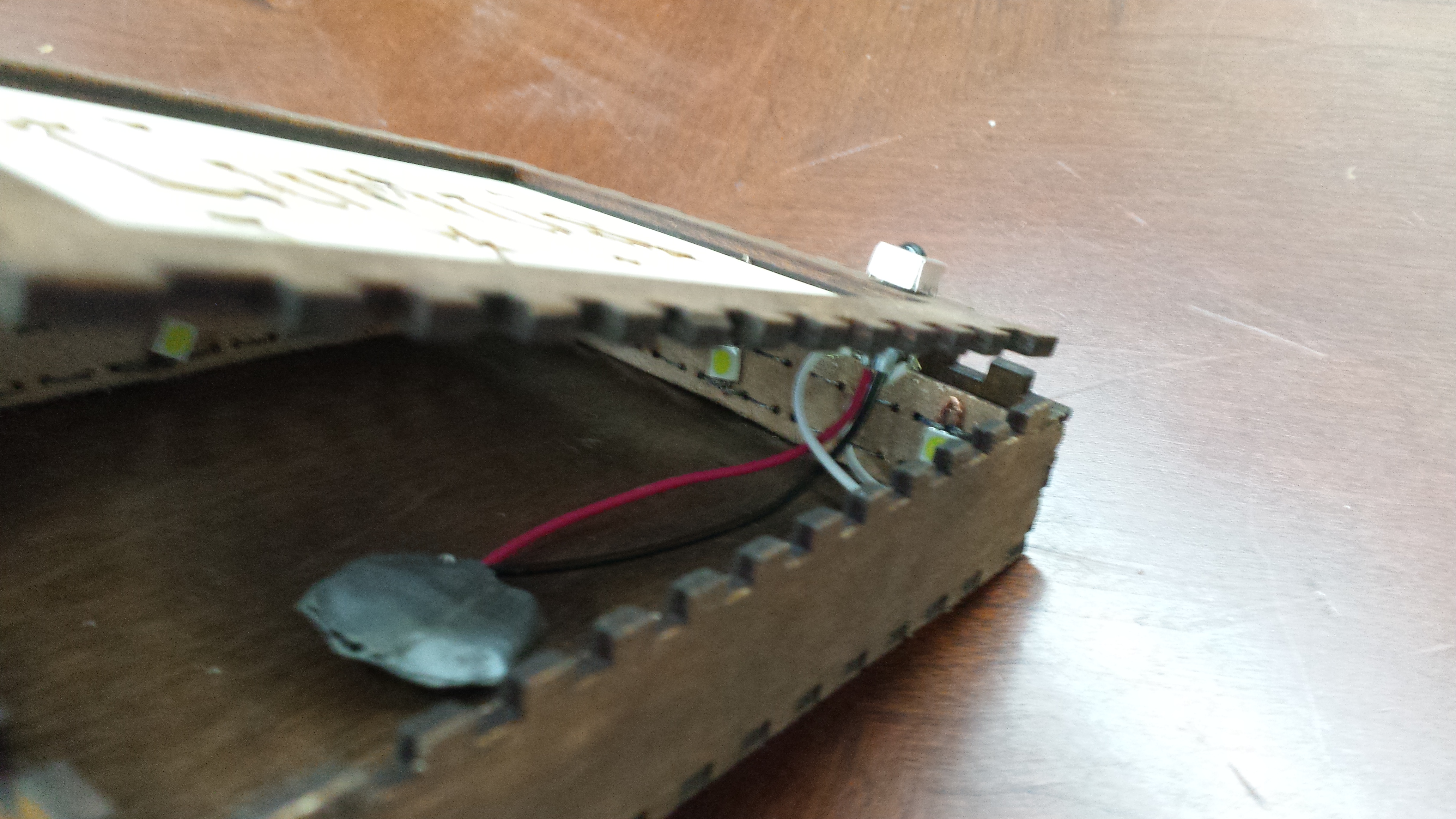
Attach the positive and negative terminals of your LED strip to the correct wires of the IR sensor -- see the second image above for how mine looked. In order to do this, I had to sew on some wire leads to the LED strip -- see the first image above. Use heat shrink or tape to wrap around exposed parts of the wire so you don't get a short circuit (see second image above)!
Once that's correct, check it one more time with a remote control before gluing the LED strip around the perimeter of the box and finally closing the lid (I didn't glue the top lid on, since I knew I'd have to remove it in the future if the battery dies). Make sure your IR sensor sticks out if your light doesn't flash on when the IR sensor is hidden in the box.
Finished and Future Work
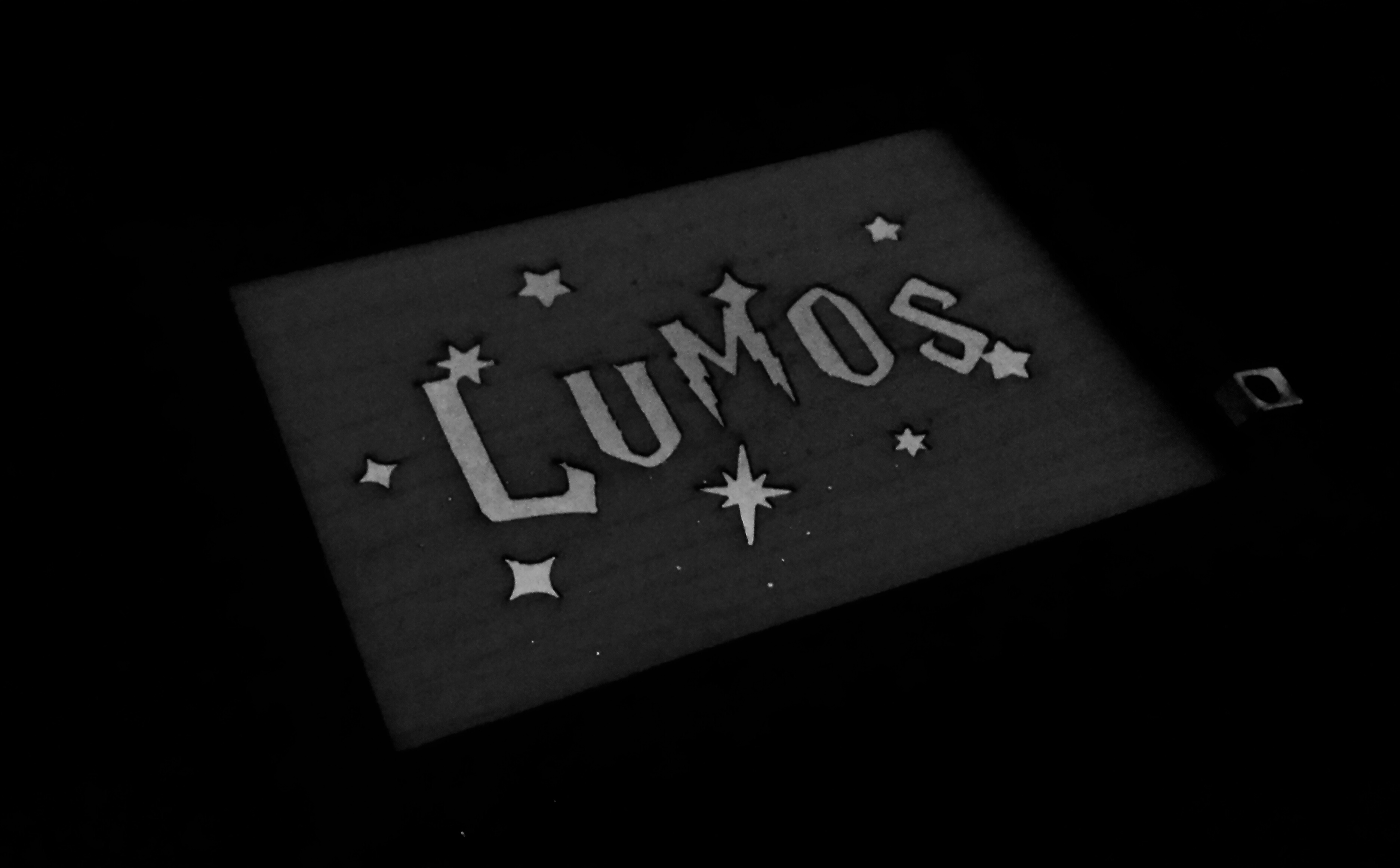
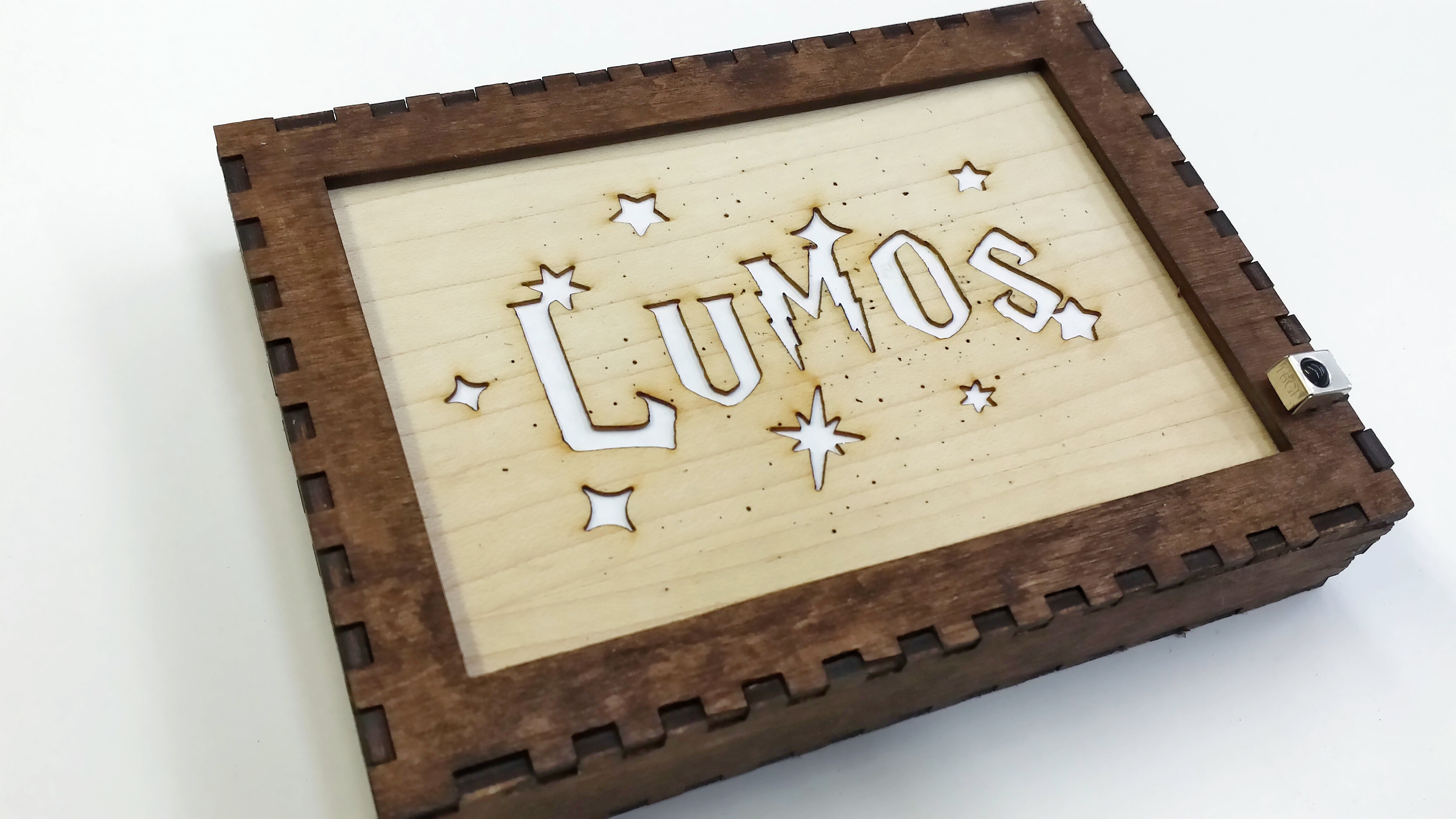
Now that this light is done, show off your wizarding prowess by pointing your IR wand at the light and saying, "Lumos" (and pressing the button switch, covertly of course -- or hide a TV remote in your hand).
This was a quick circuit, but to make it more robust many options could be implemented:
- I didn't counteract noise in my IR sensor, but you can hook up a micro controller to the sensor to get rid of it. Try this tutorial on how to do so with an Arduino that you have lying around (or similar micro controller).
- Technically the wand should have the LED pulsing at ~38kHz so attach a pulse controller chip to the LED somehow. You're a smart cookie so I'm sure you can figure that out (or let me know if I can help you somehow).
- If you're worried about the IR sensor not having a high enough supply current to power all of your LEDs, you might want to look into adding a transistor switch to amplify your current. This great tutorial by Sparkfun gives you an overview of how this works.
- I only have the LEDs on with you press and hold the wand button, and off when I release. But ideally it would be great to have the LEDs on when I press the button and let go the first time, and off when I press again. In that case you would need to program a micro controller hooked up to the IR sensor in order to control this feature, but that's a problem for someone else to figure out... perhaps you?
As always, leave comments and questions below, and I'll get to them when I can. Enjoy.