IR Thermal Camera
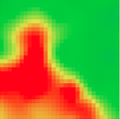
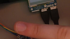
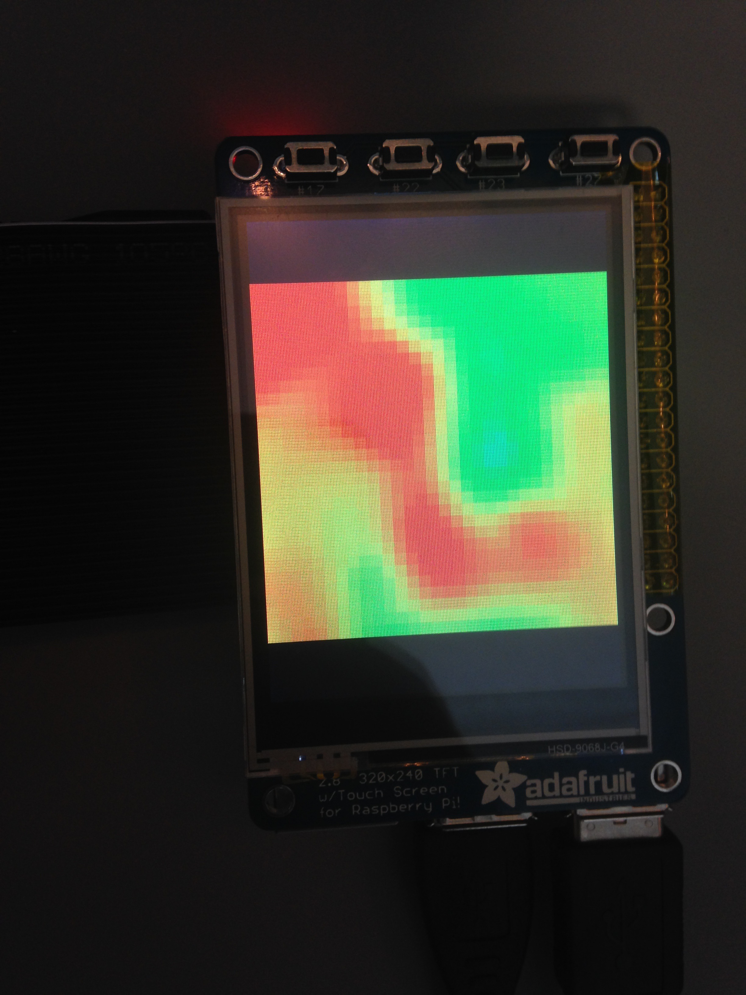
Have you ever watched a sci-fi or action movie, where the characters move into a pitch black room and switch on their “thermal vision”? Or have you ever played Metroid Prime and remember the thermal visor that the main character got?
Well I have done both of those things and think it’s rather neat. Visible light is an excellent way for us to utilize our eyes to see the world around us, but there are some shortcomings of our current evolutionary iteration of a lens eyeball, namely that it doesn’t work without visible light having been introduced to our system. It can also reflect weird and distort the image captured by it.
Thermal cameras don’t have these problems, they detect the infrared wavelengths of light that are naturally emitted by any warm body. This means they work in the dark, and they don’t really reflect off of surfaces so much as visible light wavelengths do. This makes them handy to use in the absence of a visible light source to detect warm bodies, as well as it can be used to more accurately track the kinematics of a warm body in motion more accurately than a conventional camera.
We decided to make a thermal camera because we thought it would be a neat expansion on turning IR input into a visual representation. We ended up utilizing a small array of IR sensors called a Grid Eye AMG8833 and a small computer called a Raspberry Pi that is capable of expanding the only 8x8 input of the AMG8833 to an output of 32x32, which provides a decent resolution to the image the screen produces.
This is our instructable to make a little thermal camera, use this to impress your friends or dominate in some kind of indoor game played in the dark, although you will have to find a portable power supply sufficient to run the Pi on.
Preparation & Safety
Before you start, you should know:
Infrared Radiation, or IR, is a type of light that radiates from an object due to its thermal energy. The IR Sensor can detect this radiation, and then needs programs to process the signal and display the image.
This website provides the software to format an SD Card:
https://www.sdcard.org/downloads/formatter_4/index...
This website provides the NOOBS OS to run the Raspberry Pi:
https://www.raspberrypi.org/downloads/noobs/
Further information about the AMG8833 IR sensor can be found here:
https://learn.adafruit.com/adafruit-amg8833-8x8-thermal-camera-sensor
Safety:
It is advised that you connect the circuitry before plugging in the Raspberry Pi. We also advise that you keep the assembly enclosed in an encasement to protect the hardware from stray currents, impacts, and liquids. Finally, do not unplug the USB to shut down the Raspberry Pi, as this could damage the device. Instead, use the "shutdown now" command.
Gather All Necessary Components and Tools
Make sure you have all of the following components:
-2.8" PiTFT touchscreen display (https://www.adafruit.com/product/1983)
-Adafruit AMG8833 8x8 Thermal Camera Sensor (https://www.adafruit.com/product/3538)
-Pi T-Cobbler+ and 40 pin ribbon cable (https://www.adafruit.com/product/2028)
-Raspberry Pi 3 B+ (https://www.adafruit.com/product/3775)
-4 female/female jumper wires
-MicroSD card and adapter (https://www.amazon.com/Samsung-MicroSD-Adapter-MB...)
Also make sure you have all of the following tools for assembly and formatting:
-Computer with internet access
-Mini USB cable
-Keyboard
-Mouse
Attach PiTFT to Cobbler
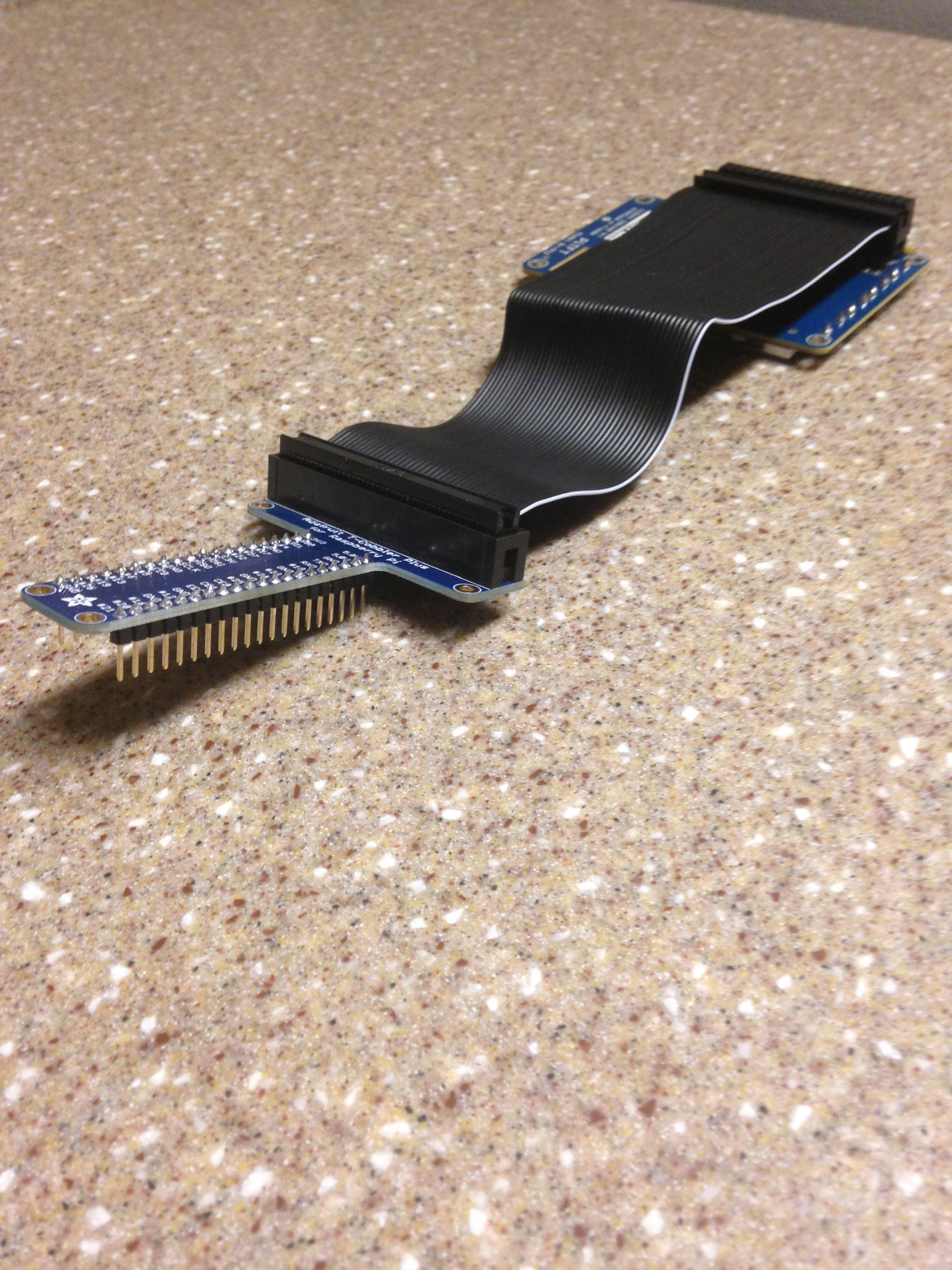
Use the 40 pin ribbon cable to connect the PiTFT male 40 pin mount to the Cobbler 40 pin mount. Note: the white wire on the 40 pin ribbon should be positioned according to the photo.
Attach PiTFT Display to Raspberry Pi
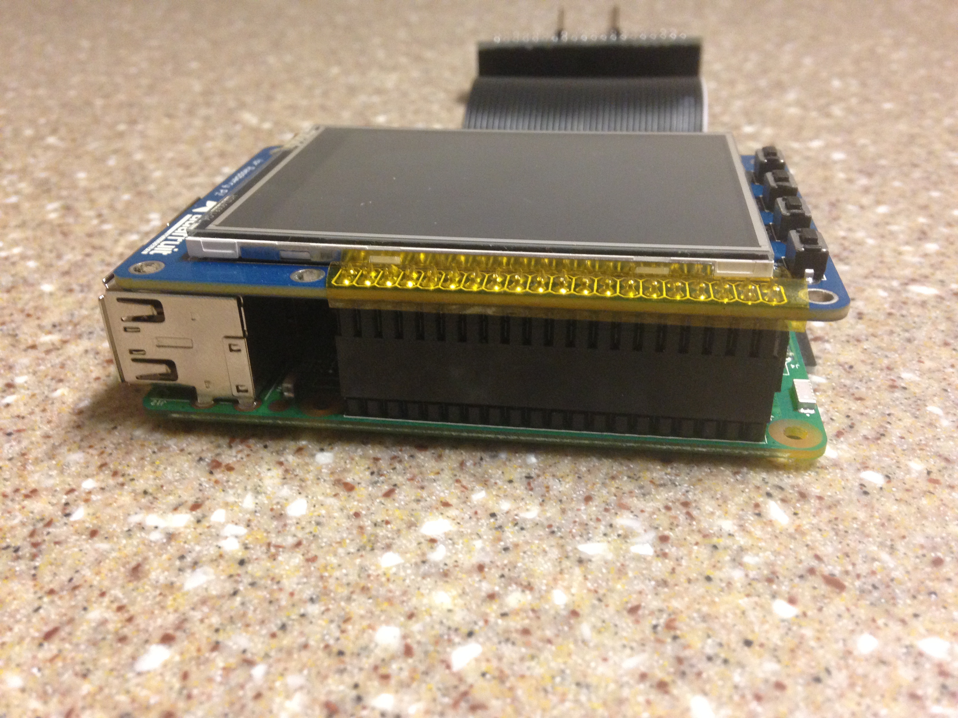
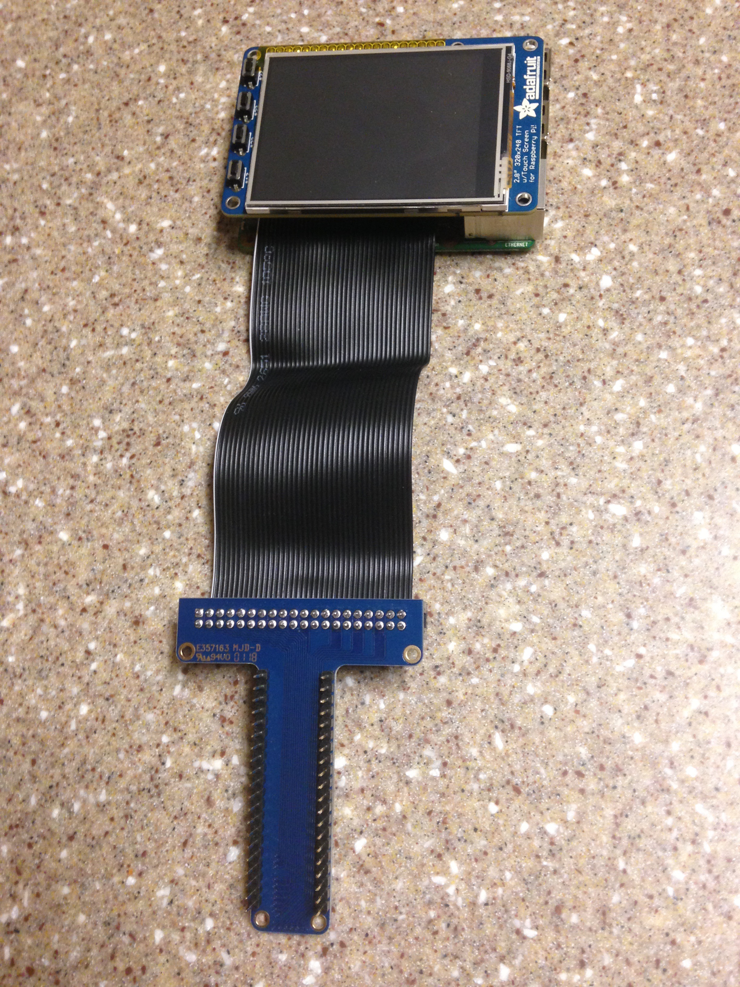
Attach the PiTFT Display directly to the Raspberry Pi by lining up the 40 pin female connector on the PiTFT with the male mount on the Raspberry Pi.
Attach 8x8 Thermal Camera Sensor to the Cobbler
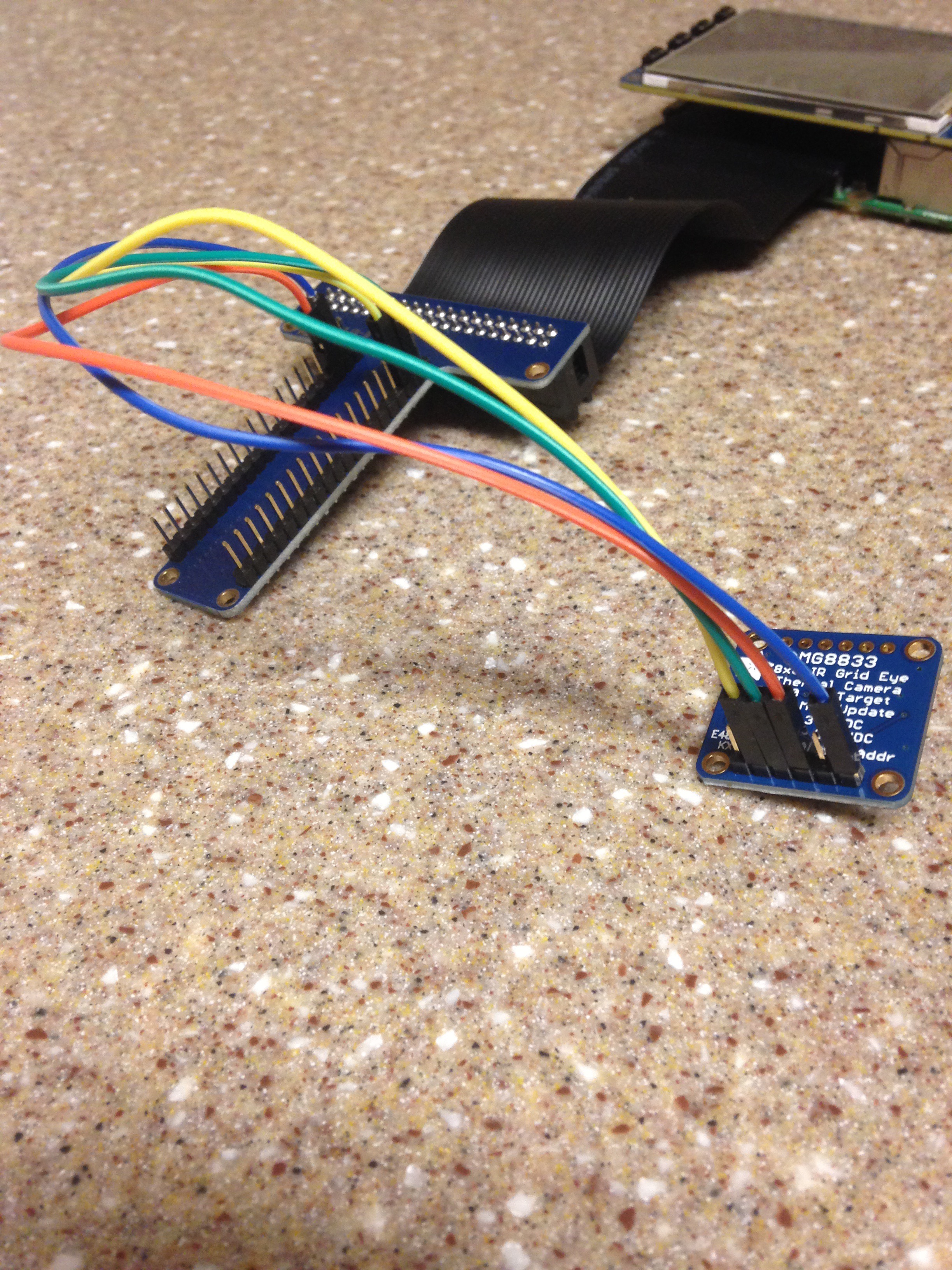
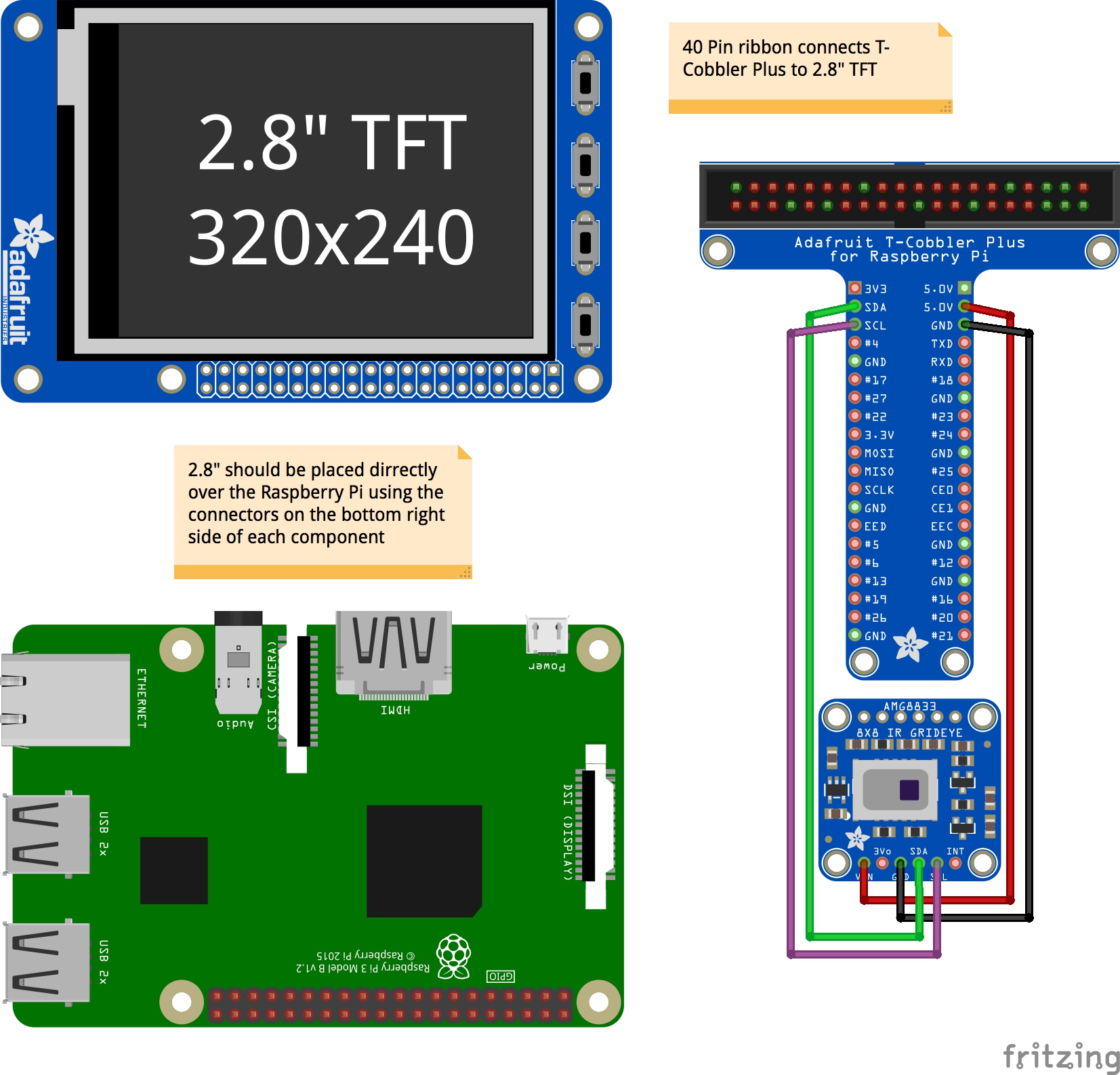
Use the four female/female jumper wires to attach the 8x8 Thermal Camera Sensor to the Cobbler.
Vin connects to 5V on Cobbler, and the rest of the pins match up with the same labels between each pin on the thermal camera and on the Cobbler. The "3Vo" and "INT" pins on the thermal camera are left unattached.
The finished circuit is shown above.
Download SD Memory Card Formatter
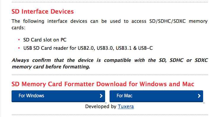
Open the site https://www.sdcard.org/downloads/formatter_4/index.html and download the SD Card Formatter using the appropriate file for your computer.
Format the SD Card
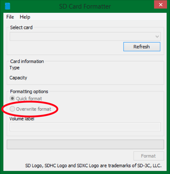
Open the SD Card Downloader program on your computer and select the card, then select "Overwrite format" and run the program. This will partition the SD card into something called a Fat32, which is what is needed to place an OS on the card.
Download Noobs
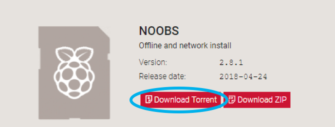
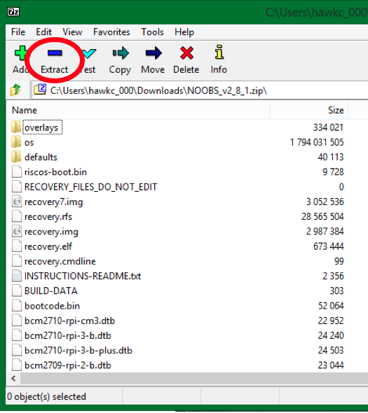
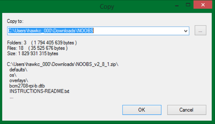
Go to https://www.raspberrypi.org/downloads/noobs/ and download the zip file for the Noobs software.
Open the zip folder from your downloads and click extract. Add the name "Noobs" to the end of the destination name to create a new folder holding the extracted files.
Getting the OS Onto the Raspberry Pi
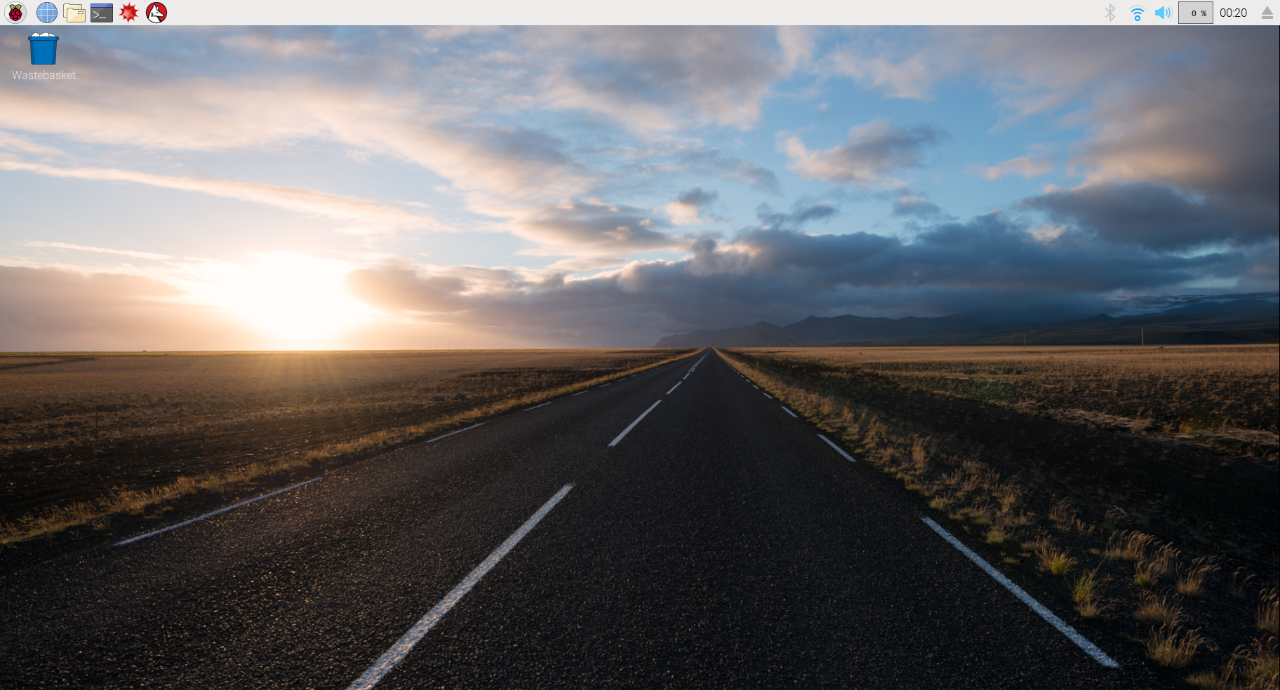
Copy the extracted files from the Noobs folder to the formatted SD card. Eject SD card and insert into the Raspberry Pi. Plug the Pi into a monitor via HDMI and then power the Pi by plugging it into the computer via USB. You will want to hook it up to a mouse and keyboard as well. Follow boot instructions and install "Raspbian OS" Be sure to select keyboard language "American English." This will put the OS onto the Raspberry Pi and open up the desktop screen.
Set Up the PiTFT
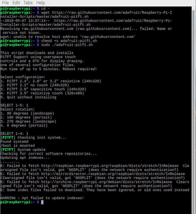
Open up the internet connections and ensure that the Pi has access to the internet.
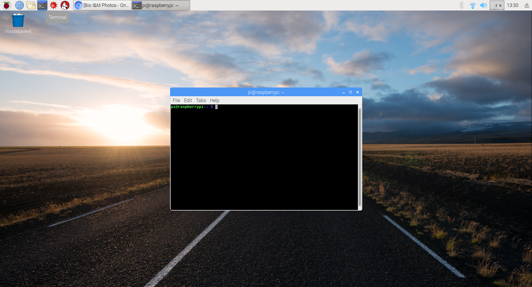
Open the Terminal button on the top bar of the desktop and type in the following code:
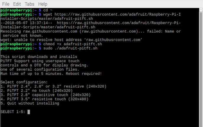
cd ~
wget https://raw.githubusercontent.com/adafruit/Raspberry-Pi-Installer-Scripts/master/adafruit-pitft.sh
chmod +x adafruit-pitft.sh
sudo ./adafruit-pitft.sh
Then when the program runs, for what we want type 1 then enter for the first query, 1 and enter again for the second.
Troubleshooting Tip: if you get an error saying that there are files missing, see the next step and then return to this one, starting over with "sudo ./adafruit-pitft.sh"
When asked if you want the console to appear on the pitft display, type "y" and then hit enter.
Then type "y" when asked reboot now.
If You Are Getting an Error Setting Up the PiTFT...
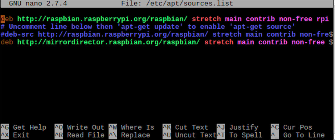
NOOBS is likely missing a few system files that are necessary to run the pitft software, if you got an error at some point during the last step, these are the instructions to correct the error. The issue is that there needs to be additional files in a particular repository, open the repository by typing in the following command:
sudo nano /etc/apt/sources.list
This will open a terminal editor for this repository and you are able to add files here by inserting additional lines. The additional lines are actually given to you by the error message including the source of the files, this was the line that I had to type in to get my missing files:
deb http://mirrordirector.raspbian.org/raspbian stretch main contrib non-free rip firmware
To save this change, the key command is ctrl+O for "Write Out", then ctrl+T then enter to find the file, then overwrite the original file in the proper folder. Note, the "proper file" is the name of the file you opened, aka "/etc/apt/sources.list" Be sure not to select the .d version of the file. Then close the window once it is saved.
Return to the previous step to finish the process of setting up the pitft.
Update Pi and Get Necessary Software
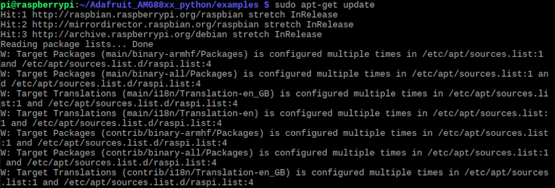
At this point, the PiTFT will be your console.
Troubleshooting Tip: if you're having trouble operating just using the PiTFT console, you can type the command startx to open the full desktop again.
To update the Pi, type in this command:
sudo apt-get update
Then once the Pi is updated, we will install the software for using the AMG8833. Type in the following commands:
sudo apt-get install -y build-essential python-pip python-dev python-smbus git
git clone https://github.com/adafruit/Adafruit_Python_GPIO.git
cd Adafruit_Python_GPIO
sudo python setup.py install
sudo apt-get install -y python-scipy python-pygame
sudo pip install colour Adafruit_AMG88xx
Enable the I2C Bus to Allow Communication With the AMG8833
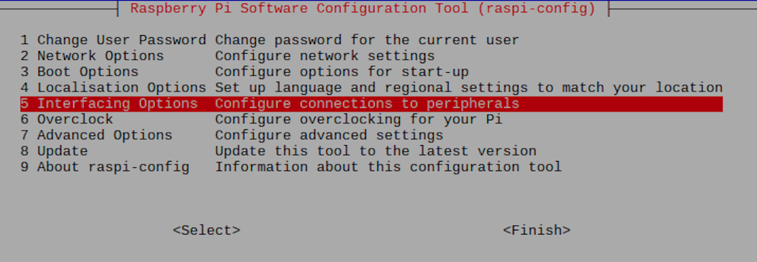
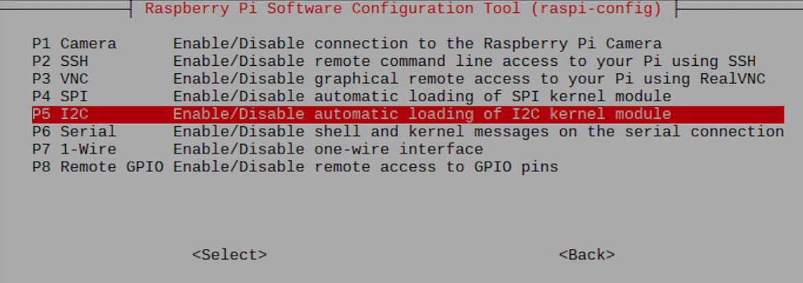
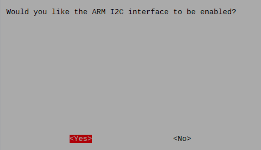
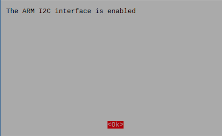

To enable the I2C bus, we need to change the Pi's configuration.
Type:
sudo raspi-config
Then use the arrow keys to navigate down to the 5th option reading "Interfacing Option" and hit enter.
Navigate down to P5 "I2C" and hit enter.
Enable the I2C by hitting enter on the "Yes" option of the enable query.
Hit enter when it says that it has been enabled.
Use the right and left arrow keys to navigate to "finish" then hit enter to exit the config. window.
Verify That the Sensor Is Attached and Detected by the I2C

To just verify this before proceeding further, enter the command:
sudo i2cdetect -y 1
If an array appears with only dashes except for a 69 in bottom row of the 9th column, then you're system is working properly.
Use the Camera
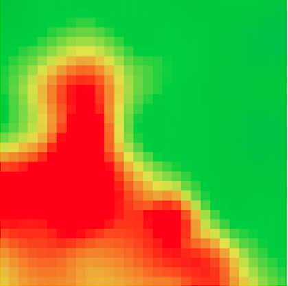

To start the camera, enter the commands:
Troubleshooting Tip: For this step, the Pi is using an English keyboard that uses Shift+\ to type "~" (forwardslash is the key between backspace and enter on the keyboard)
cd ~/
git clone https://github.com/adafruit/Adafruit_AMG88xx_python.git
cd Adafruit_AMG88xx_python/examples
sudo python thermal_cam.py
This will open the camera window. You now have a functional thermal camera, feel free to point it at things.
Also since we are only using the pitft as a display, you will need to physically disconnect the power to the AMG8833 in order to return to the command terminal window. Once back to the command window, if you'd like to shut the Pi down, type in:
shutdown now
Safety Tip: Do not disconnect the Pi from power prior to it completing its shutdown process, this can damage the SD card.
Further Idea: Editing the Code to Change the Range of Temperatures Displayed
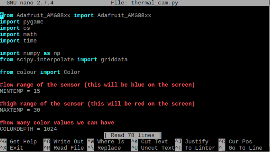
If you want to adjust the range that the example code originally had, disconnect the power to the thermal sensor and type in this command:
sudo nano thermal_cam.py
This will open the code editor. Scroll down to the temperature range and adjust as desired. Note that they are in Celsius.
Write out the edited code and save as either a new file or overwrite the original example.
Another (arguably easier way) to do this would be to just plug the Pi back into a monitor with an HDMI and command:
startx
This will boot the homepage, and then you can just go into the files and open thermal_cam.py in the python editor and change and save it there.