IR Controlled RGB Module
Recently we got these really cool RGB bulbs that are controlled by an IR remote control. You plug them into your house hold light bulb socket, and, presto, you can set the mood of any room! They were a hit with just about all of our friends, and no party will ever be complete without them. We thought it would be cool to see how they work and offer their internals up for sale on our website. This tutorial will show you how to read IR commands from a remote, and play them back to control the RGB bulb.
Hardware and Assembly
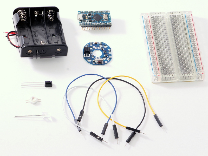
If you want to follow along with this tutorial, you will need:
- An RBG 3W or 10W Module
- Pro Micro 16 Mhz/5V
- IR Receiver
- IR LED
- 3 AA Battery Back (3 Watt Version Only)
- Breadboard
- Jumper Wires
We used a Pro Micro because of its small size, but you can use any micro-controller you have laying around. We will be using an Arduino IR library in this tutorial, so using an Arduino will make it easy to follow this tutorial.
Preparing LED Bulb Kit
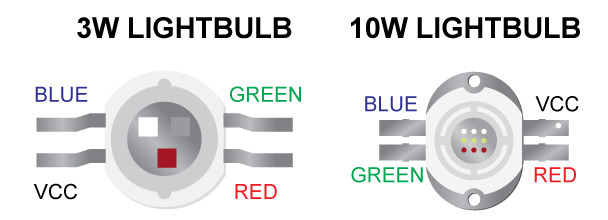
Above, you can see the two different sized LED bulb kits that we have. We have a 3W and a 10W version.
Both are full RGB, and have four pins. Three of the four pins control each of the colors, and the fourth one is a common anode (VCC). The only difference between the two, besides the power output, is the VCC input.
The 10W bulb requires 12 volts instead of 5, so it will not work our Triple AA battery holder.
Starting to Solder
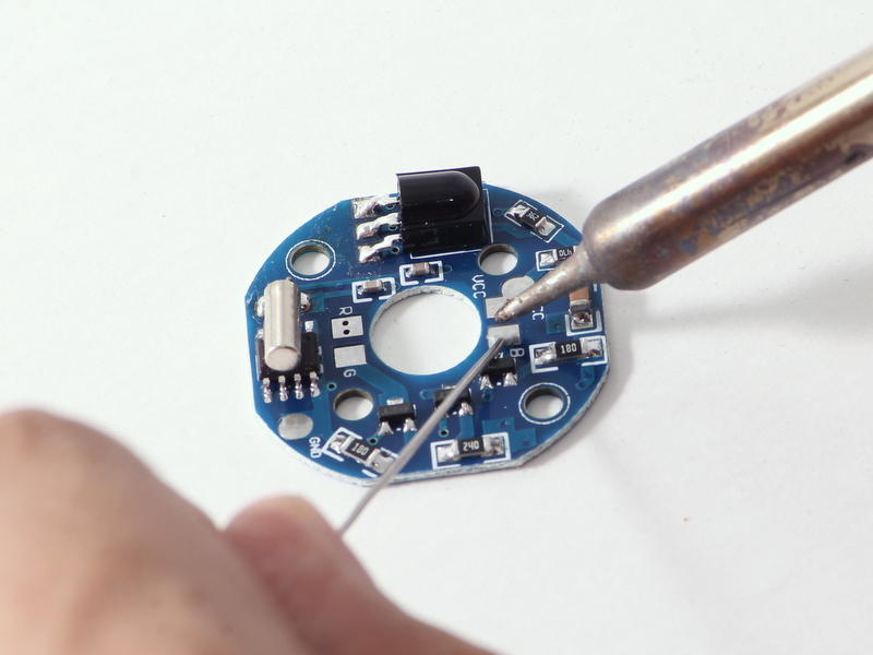
Lets start putting it all together. Start by adding some solder to one of the four pads.
We will solder one pad down to hold the LED bulb in place while we solder the other other three legs.
Connecting Leads
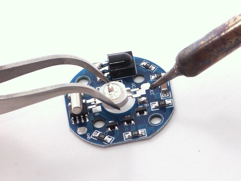
You can see each lead on the PCB is marked R, G, B, and VCC.
Use your favorite tweezers to align the bulb to the correct leads, while melting the pad with your soldering iron.
You can see in the above picture, we have a nice blob of solder to melt before placing the lead into it.
Adding the Bulb
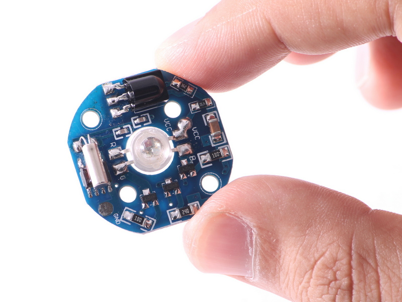
Now you can solder the other three leads of the bulb and you're done mounting it.
You can see the finished product above. Time to add a battery holder to power the bulb.
Attaching the Battery Holder
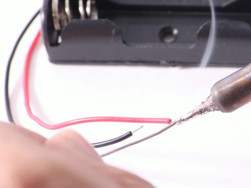
Always tin the leads of the wires so it is easier to solder to the pad.
Connecting Wires
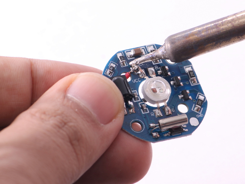
Solder the red wire to the lead marked VCC.
Connecting Wires Con.t'
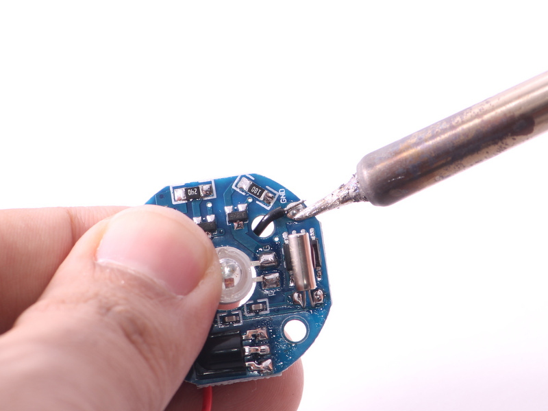
Solder the black wire to the lead marked GND.
Powering the Bulb
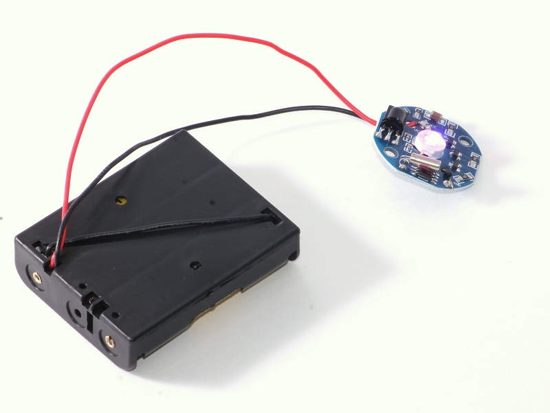
Go ahead and put 3 AA batteries in your holder, and the bulb should come on and automatically play a demo.
You can barely see it in the photo because of our camera flash, but the bulb is on. It is much brighter than it looks!
Wiring
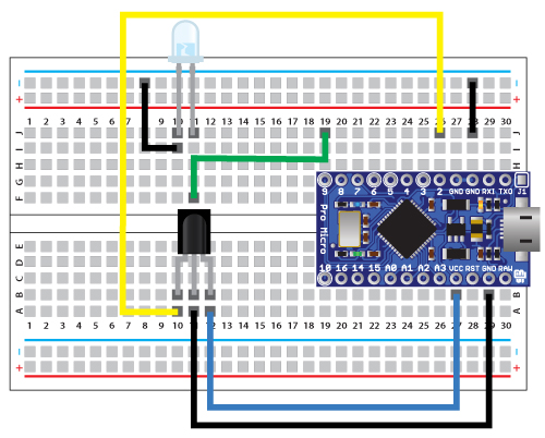
Now that we have our bulb working, we can move on to controlling it. The diagram above shows how to wire up the IR receiver and transmitter LED to the Pro Micro.
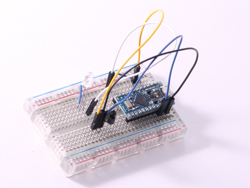
Completed Breadboard

Above, you can see what your completed breadboard should look like when you're done.
Receive Code
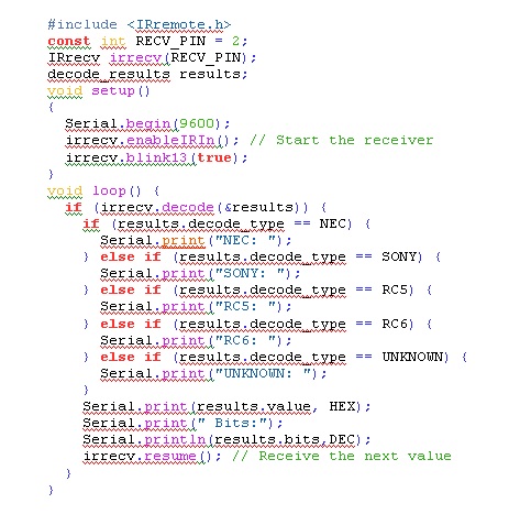
The module comes with a remote that we will use to read the commands. For this tutorial, we will use the IR library written by Ken Shirriff, which allows you to receive and transmit infrared control codes to anything you like. The latest version of the library can be downloaded here. Once you have downloaded it, open up the example called "IRrecvDemo".
The "IRrecvDemo" allows you to see the codes being sent from the remote to whatever it is you are trying to control. To send IR codes using this library, we need to know three things. We need to know the code, type, and the number of bits in the code. The first change you will notice from the original demo is the pin number. Since we do not have a pin 11 on the Pro Micro, we simply changed it to pin 2. The next thing we added was the "if structure" to check which type of code it is and print it to the serial terminal. Finally we added the "Serial.println(results.bits,DEC)" to show us the number of bits in the code.
Downloads
Testing the IR Receiver
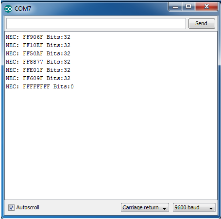
Next, you can point your remote to the IR receiver and press any button on the remote. Above we pressed the Red, Green, Blue, Yellow, On, and Off buttons in that order. Each press of a button gives us a line in the serial terminal (except the last one, which gives us two). You can see that the hex code "FF906F" represents a Red button press, and it is a 32 bit NEC code. Similarly, we have the codes for the other buttons we pressed. The reason the last button gave us two lines is because we held the button longer. The remote we are using simply sends blank codes when the button is held down.
Time to Use the IR Module!
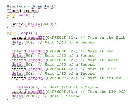
Time to try sending these codes ourselves and control the IR module! For this we will use the IRsendDemo, and add our codes to control the LED module.
In the above example, we have added the codes that we found using the IR receive demo. We are simply playing them back one by one, every two seconds. The library will automatically control Pin 8 on the Pro Micro, since it uses the Atmega32u4 processor. If you decide to use an Arduino based on the Atmega328P, you will want to use Pin 3.
That concludes our IR Controlled RGB tutorial. Now you can control the color of the LED from across the room!
Let us know about your cool projects so we can feature them on our website!
If you have any questions about this tutorial, don't hesitate to post a comment, shoot us an email, or post it in our forum at jayconsystems.com!