IOT Infrared Sensor W/ NodeMCU
by avwu99 in Circuits > Microcontrollers
4664 Views, 4 Favorites, 0 Comments
IOT Infrared Sensor W/ NodeMCU
This is an infrared sensor hooked up to a NodeMCU that can trigger and tweet out a set response on twitter.
Although this specific guide is for tweeting, you can do a lot more with the sensor and triggers, such as turning on a light or acting as a handsfree doorbell.
Have fun!
Materials
- 1 x NodeMCU
- 1 x Infrared Proximity Sensor (I bought mine at https://www.sparkfun.com/products/242)
- 1 x Infrared Sensor Jumper Wire (Bought mine at https://www.sparkfun.com/products/8733)
- 1 x Breadboard
- 1 x Micro-usb port
- Cardboard for outer casing
- A Computer (PC, Mac) that can run arduino and has usb ports.
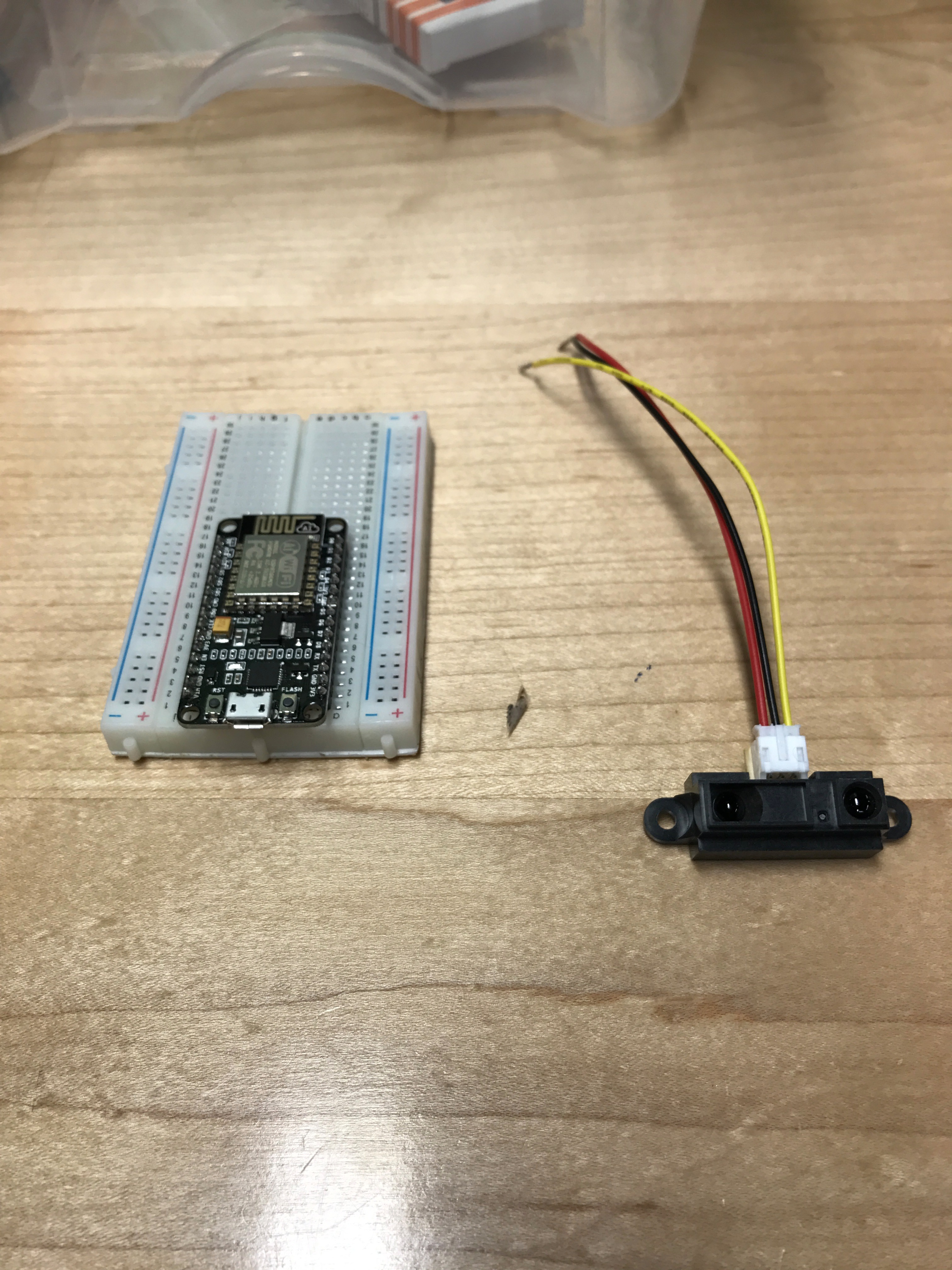
Hooking Up Infrared Sensor to NodeMCU
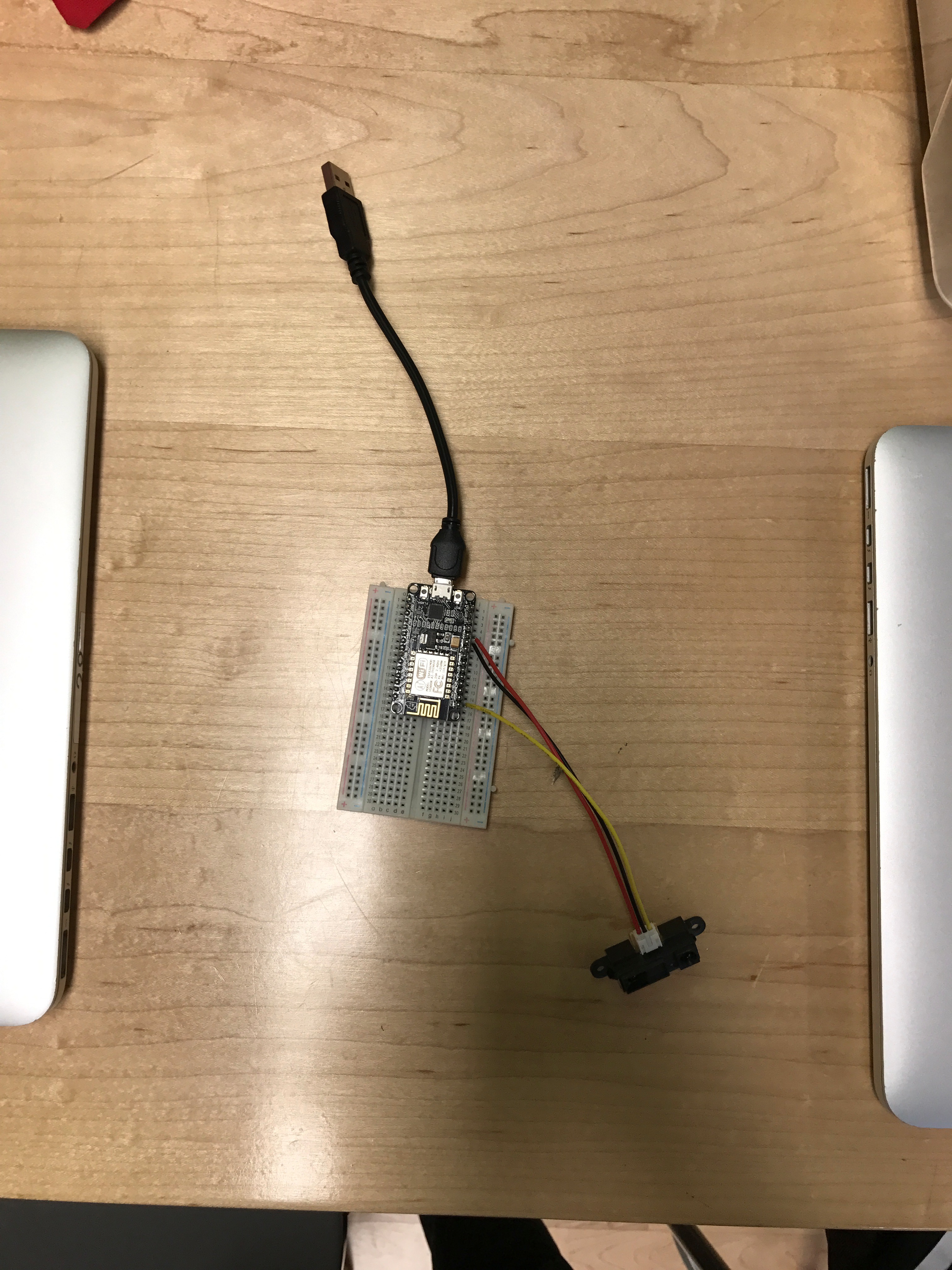
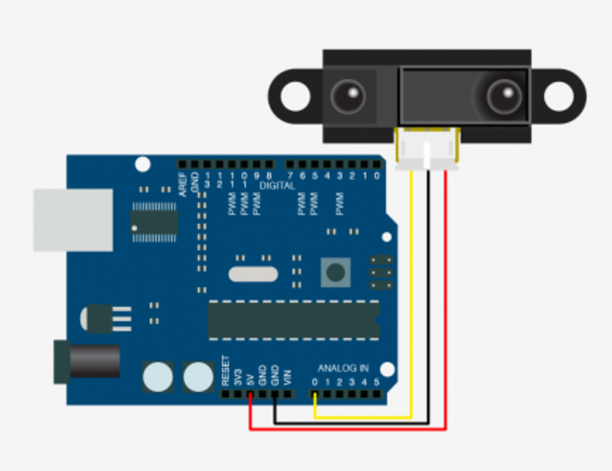
Schematics and example for hooking up the infrared sensor to the nodeMCU. (Yes it is an arduino in the diagram, but it is the same for the nodeMCU. Just use the 3v3 port instead of the 5v port when hooking the sensor up to the node).
Download Drivers for the NodeMCU / Arduino
Drivers needed for the node can be found here (ONLY FOR MAC USERS):
https://drive.google.com/file/d/0B9X6GickHKptVHBfU...
Download and install.
Arduino can be downloaded from the official website:
Settings
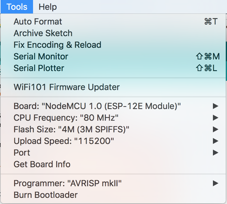
In the tools section of arduino, make sure the settings match the ones in the picture.
Creating an IFTTT Account
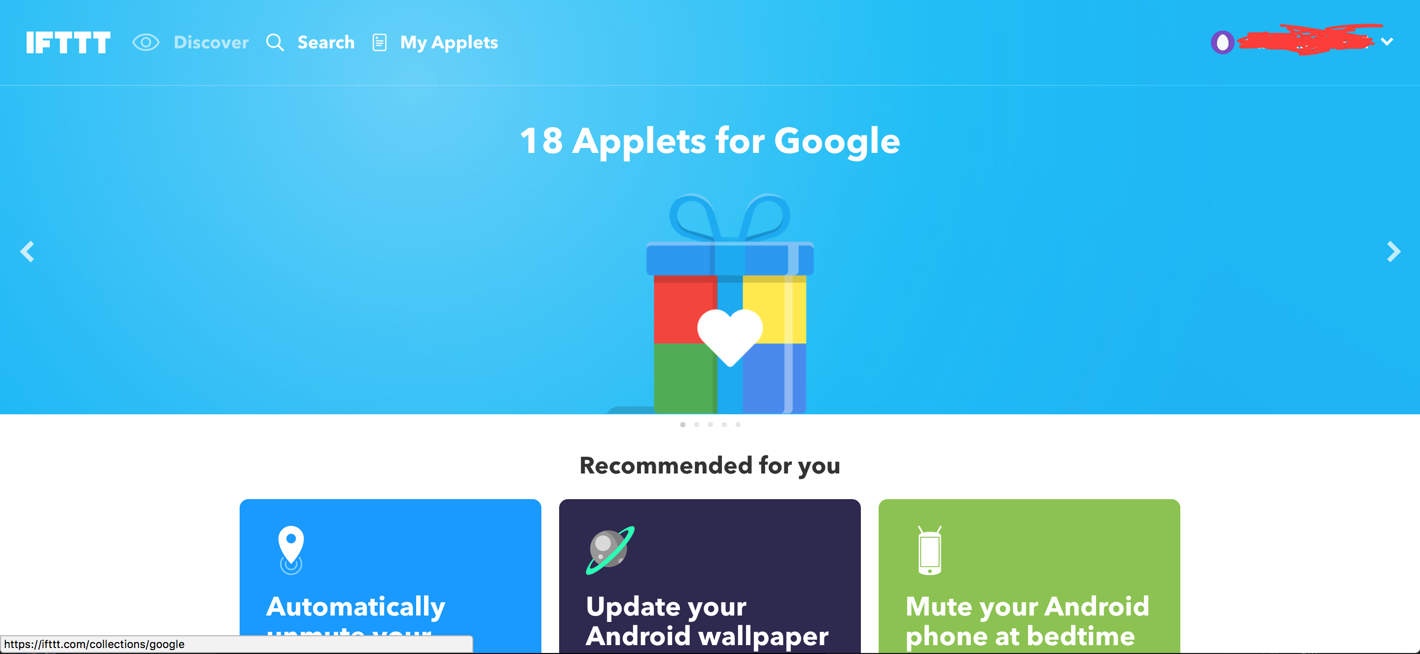
1. Create an IFTTT Account
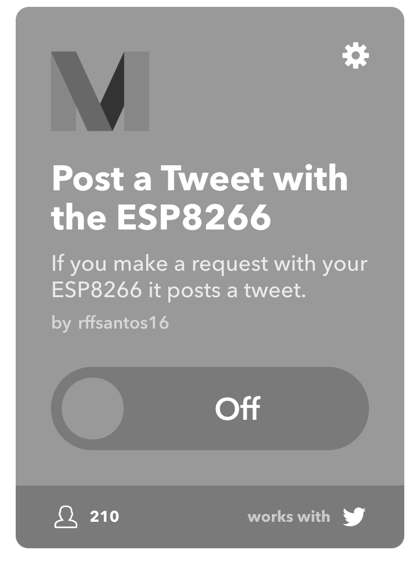
2. Look up the applet "Post a Tweet with the ESP8266"
3. Add the applet and follow through with the instructions it gives you to finish the setup.
Code
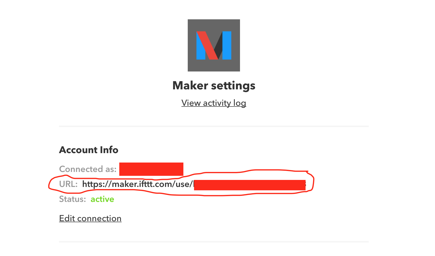
Attached is the code. Copy and replace a couple lines of code where indicated.
Info for replacing can be found in your maker settings, and on your own personal URL.
Example of where that can be found in the picture of this step.
Downloads
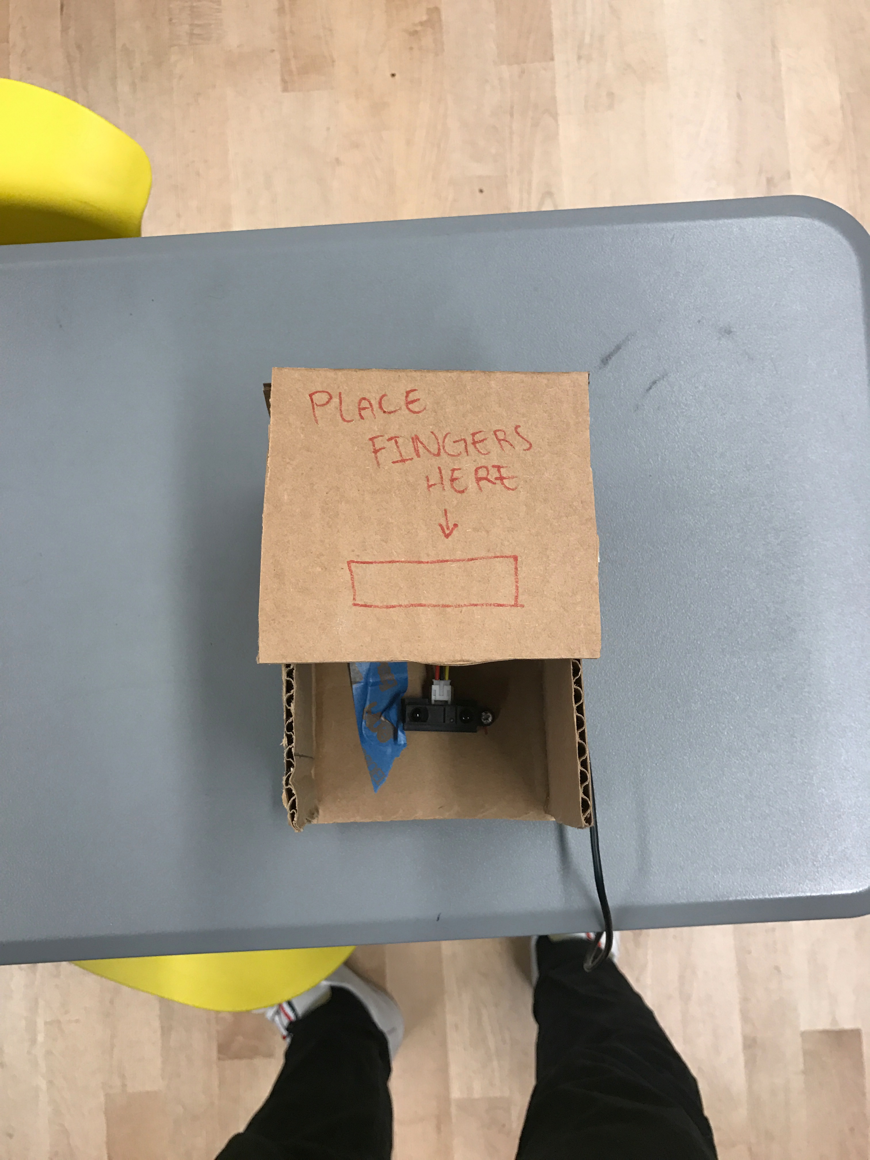
Finishing Up
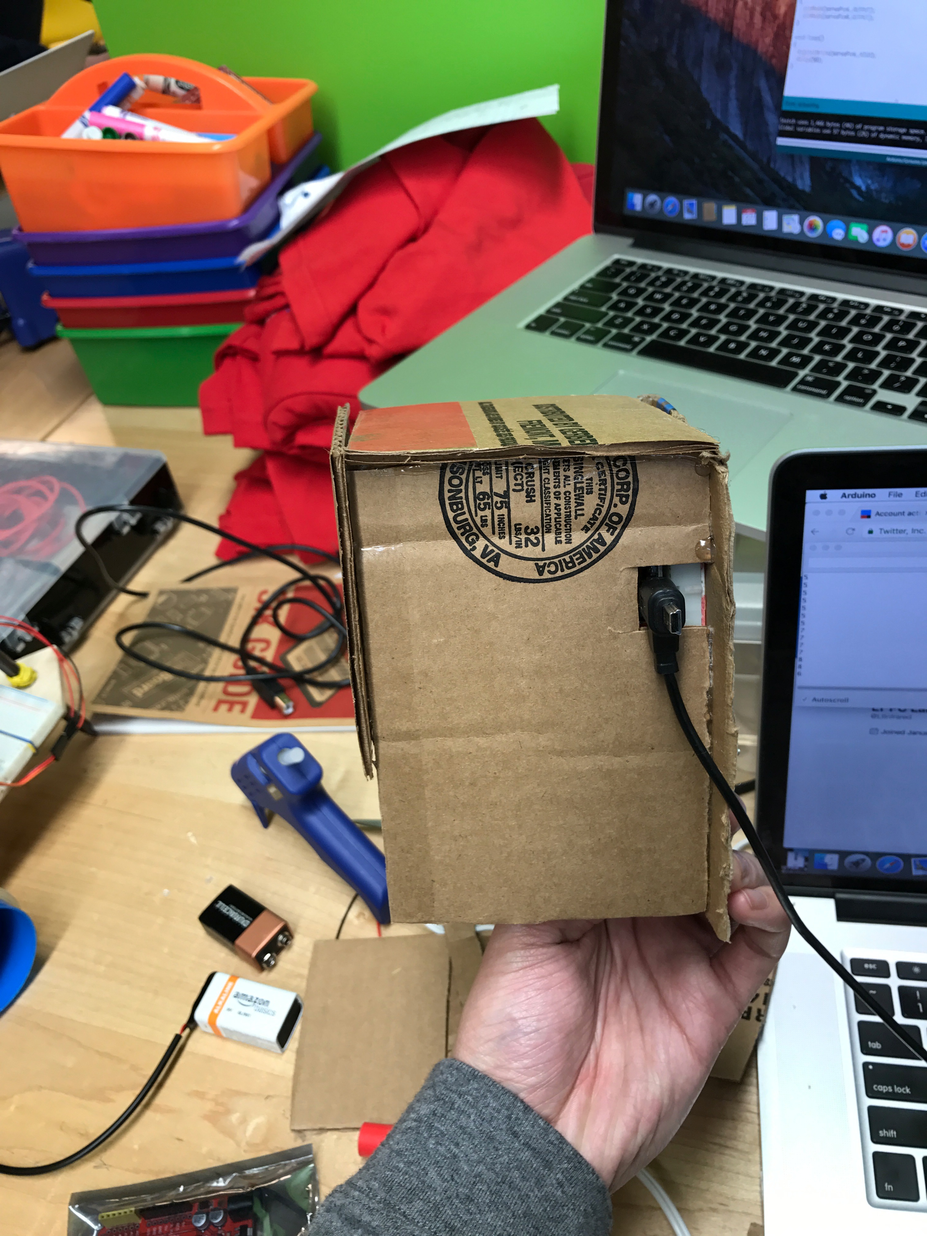
I added a cardboard exterior to keep the breadboard and wires somewhat out of sight.
After flashing the code, and making sure that the node can connect to the internet, place your hand about 4 inches above the sensor, and then check the twitter account you linked!
(Open up the serial monitor in arduino to see whats going on).