IO Control With Arduino + Esp8266 (NodeMCU) and Ubidots
by mcmchris in Circuits > Arduino
3633 Views, 4 Favorites, 0 Comments
IO Control With Arduino + Esp8266 (NodeMCU) and Ubidots
Here i show you in simple steps how to control any device over the internet using the Ubidots IoT platform and the NodeMCU WiFi module with the Arduino IDE.
Materials:
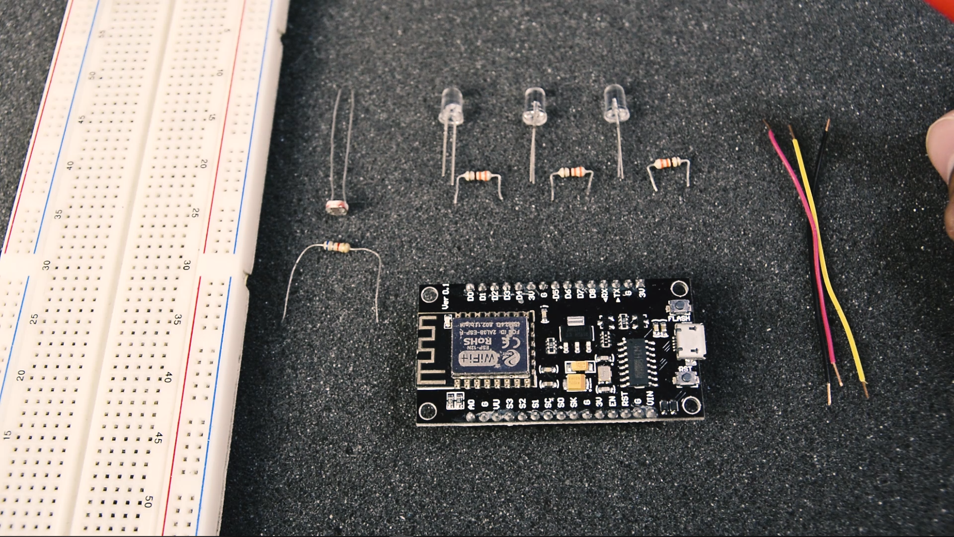
-Protoboard.
-Esp8266 (NodeMCU).
-3x LED
-3x 330 ohm resistor.
-LDR
-6.8k ohm resistor
-some wires.
Mount:
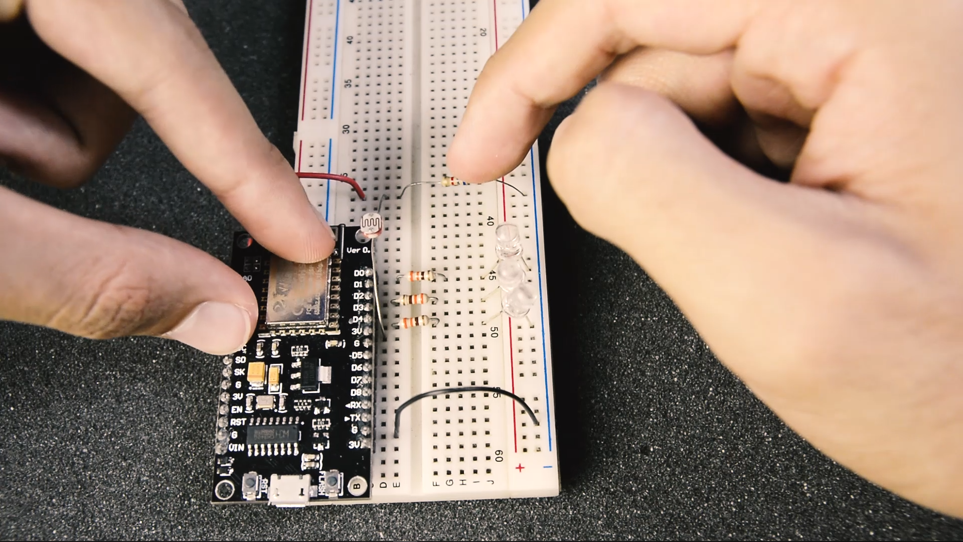
LED 1 goes to pin D0.
LED 2 goes to pin D2.
LED 3 goes to pin D4.
LDR goes to ADC pin (A0).
Upload the Code:
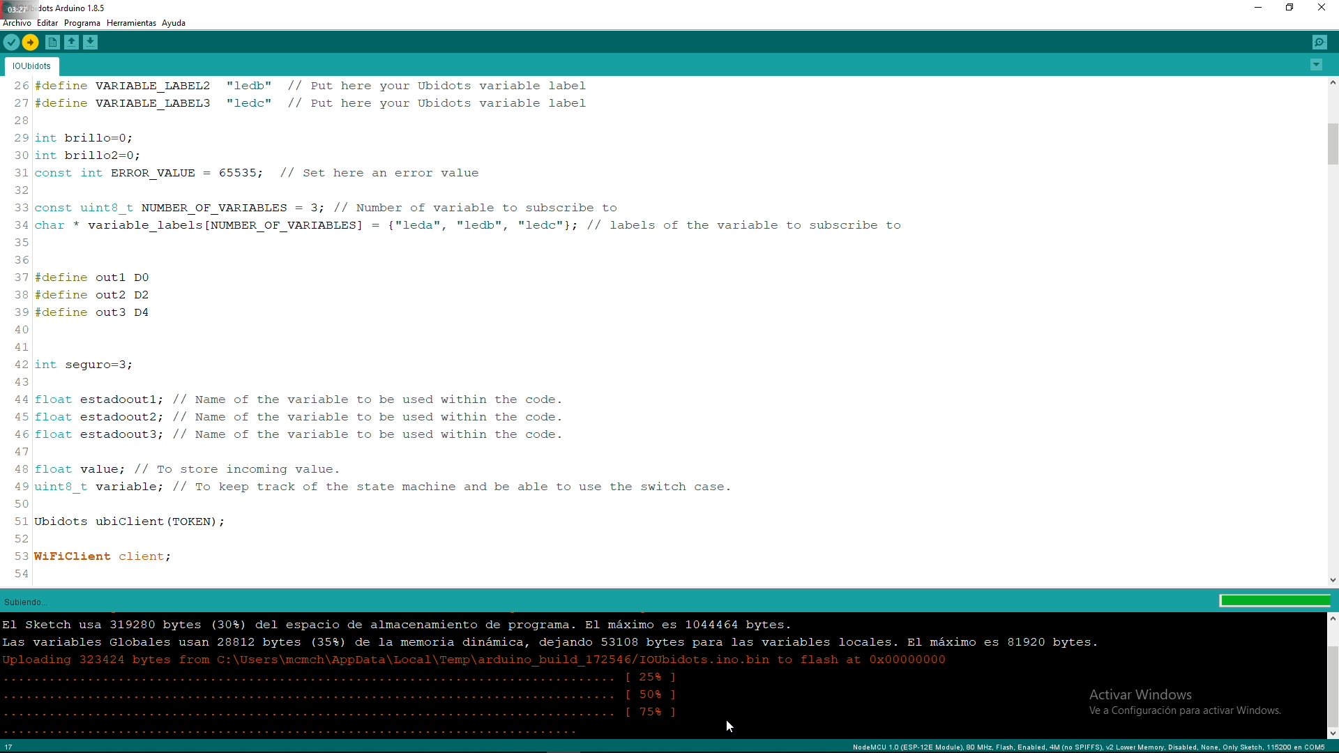
After installing the Ubidots mqtt library and downloading the code.
Link here:
Ubidots Platform:
https://ubidots.com/?utm_source=youtube&utm_medium...
Fill your credentials.
-Ubidots Token.
-WiFi SSID.
-WiFi Password.
And upload the code!
Setting Up the Ubidots Platform:
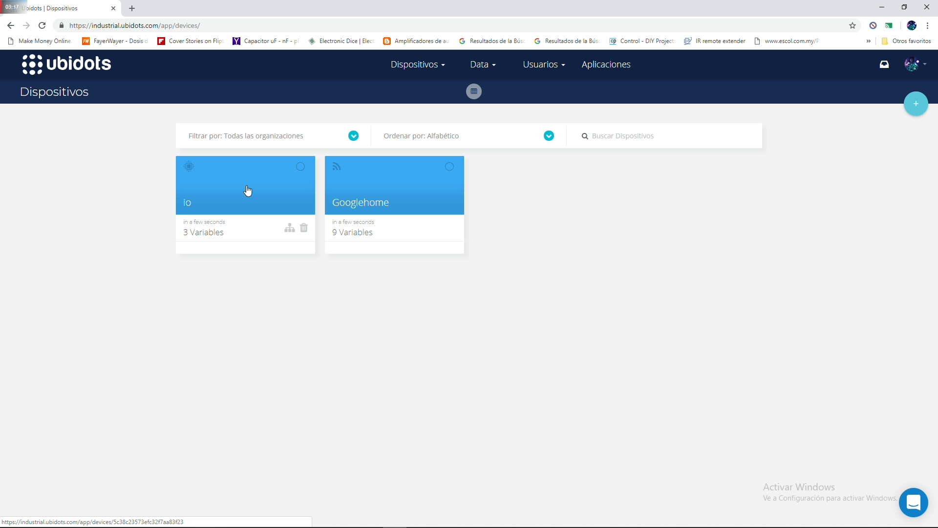
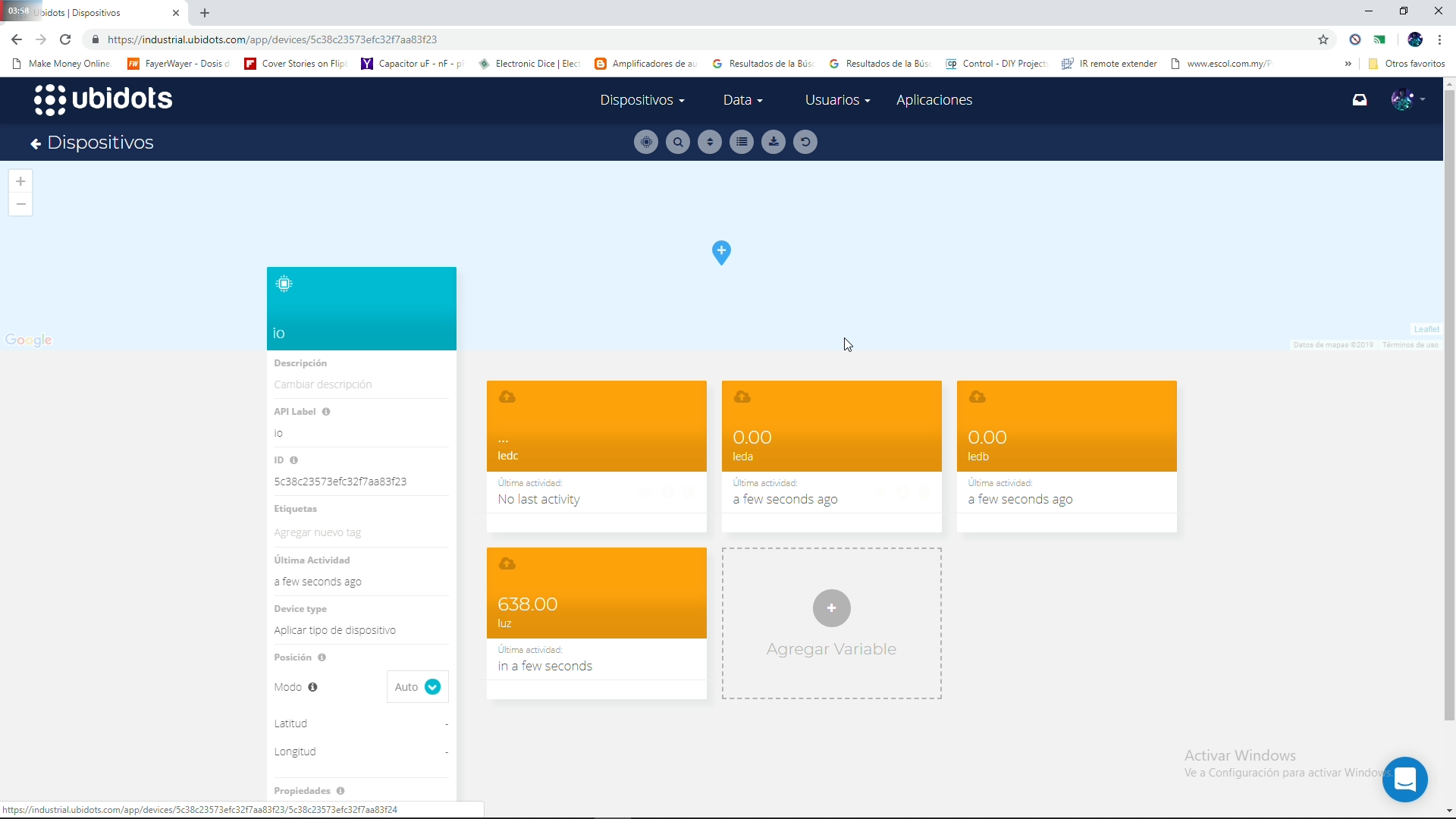
After the code is upload to the NodeMCU a device called IO shoul appear.
Then verify that it has the variables we need in it, if don't, create thems.
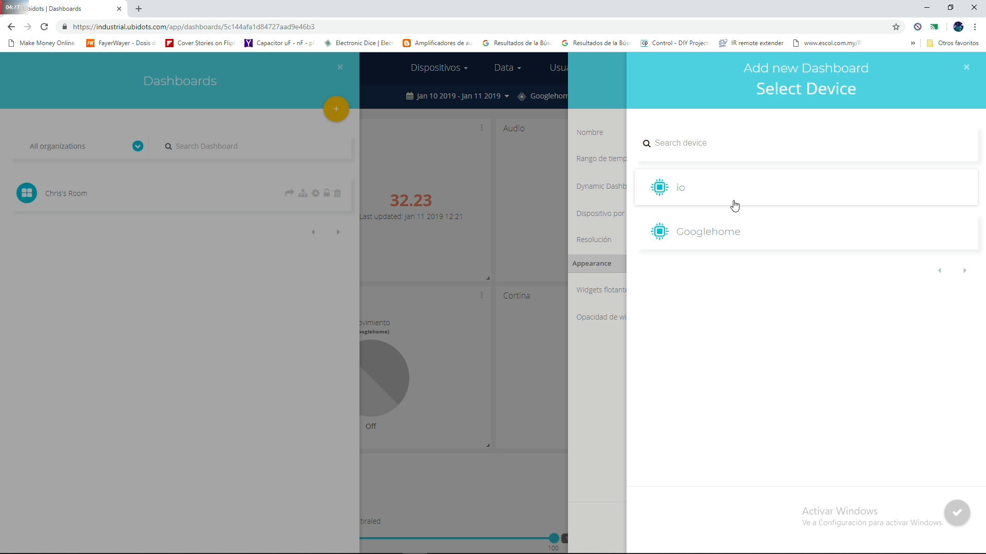
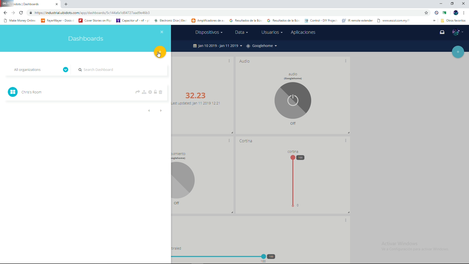
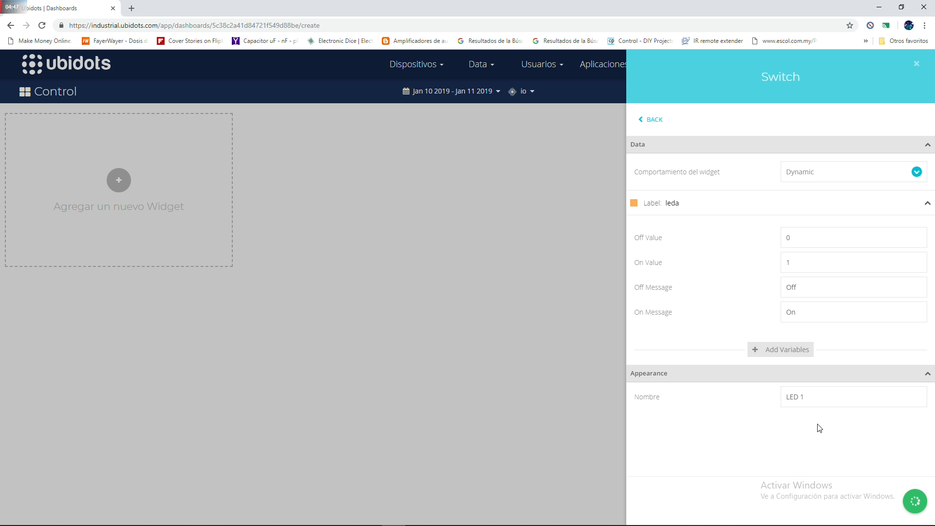
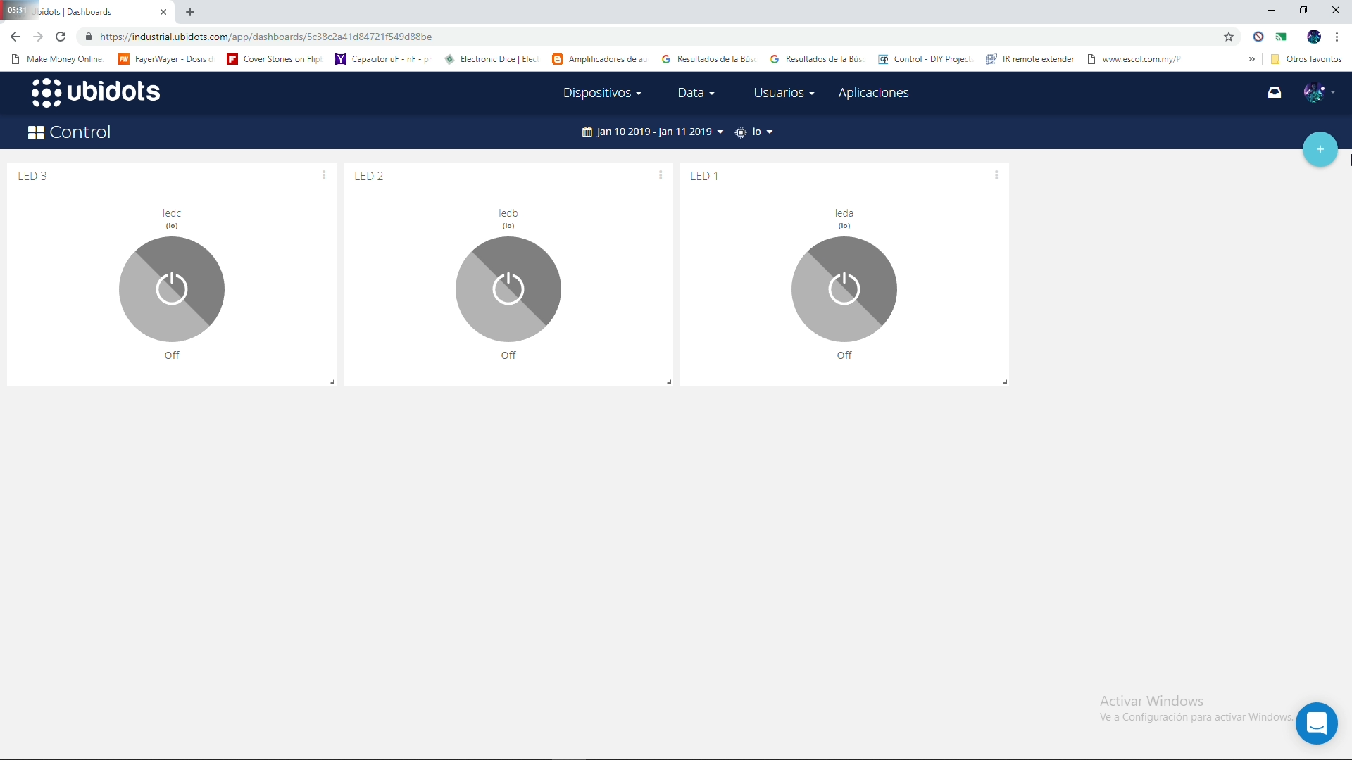
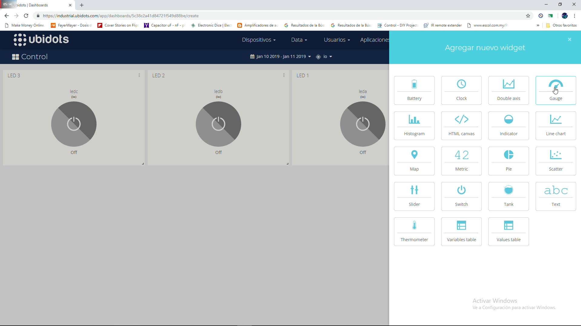
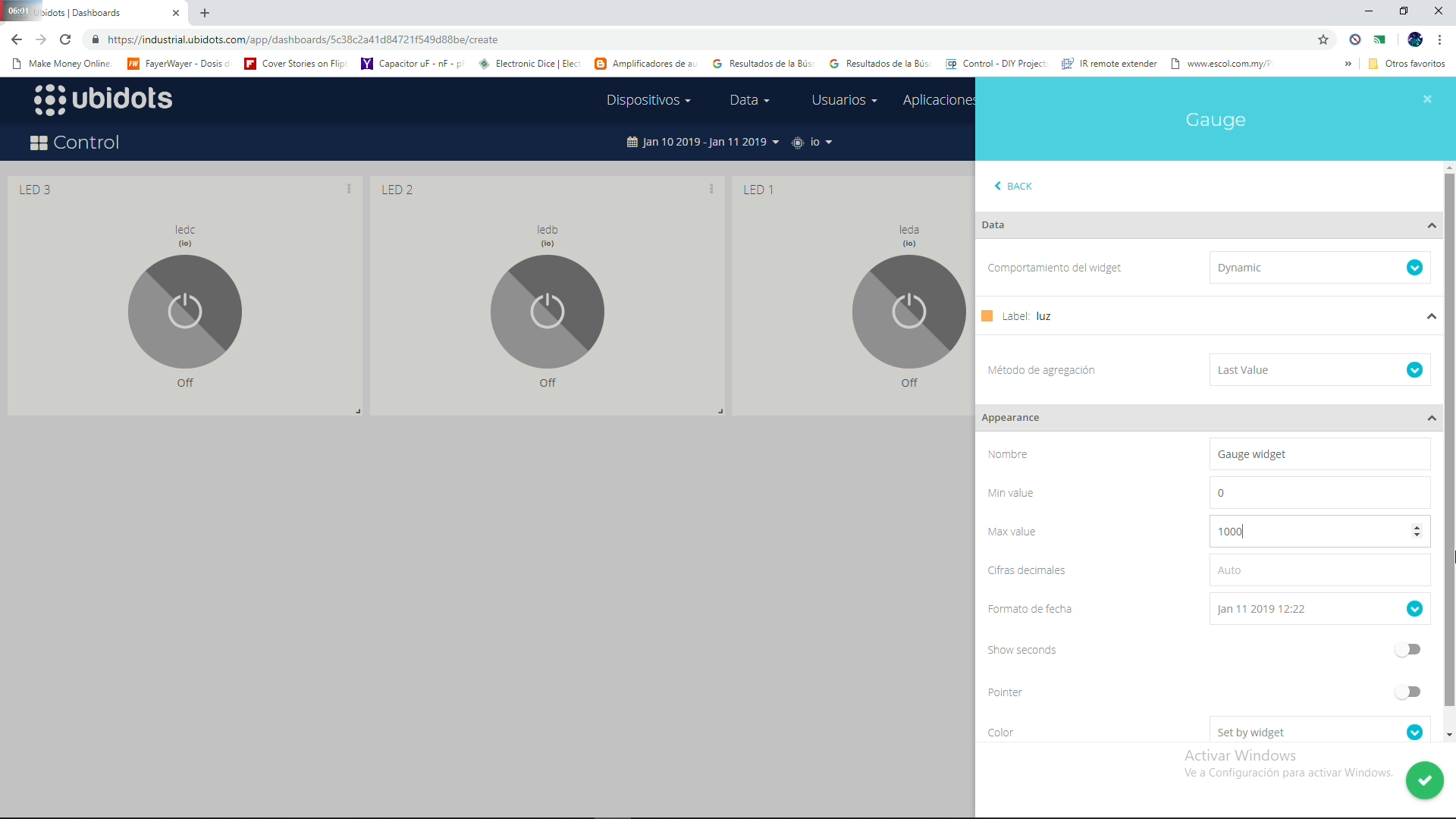
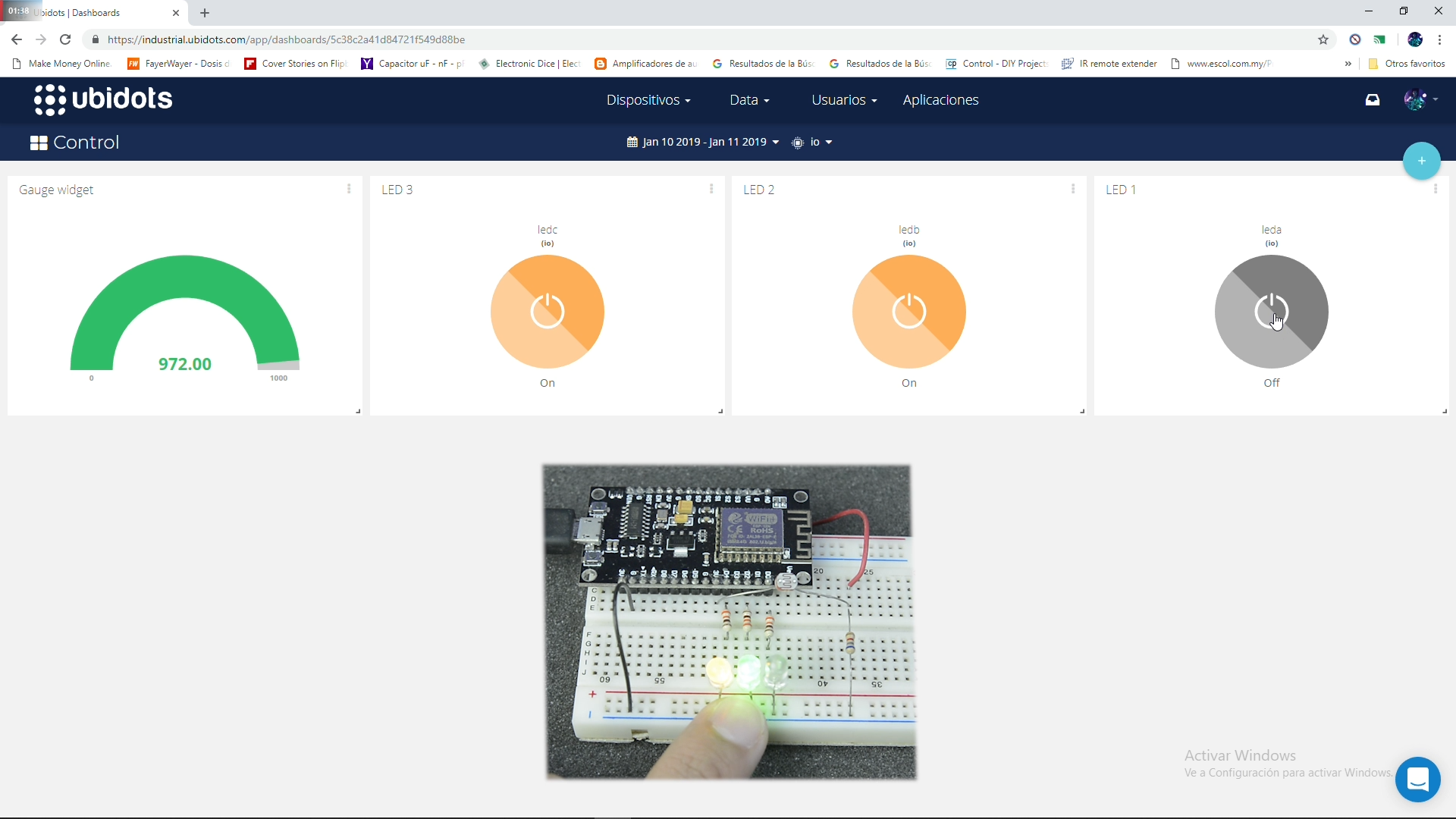
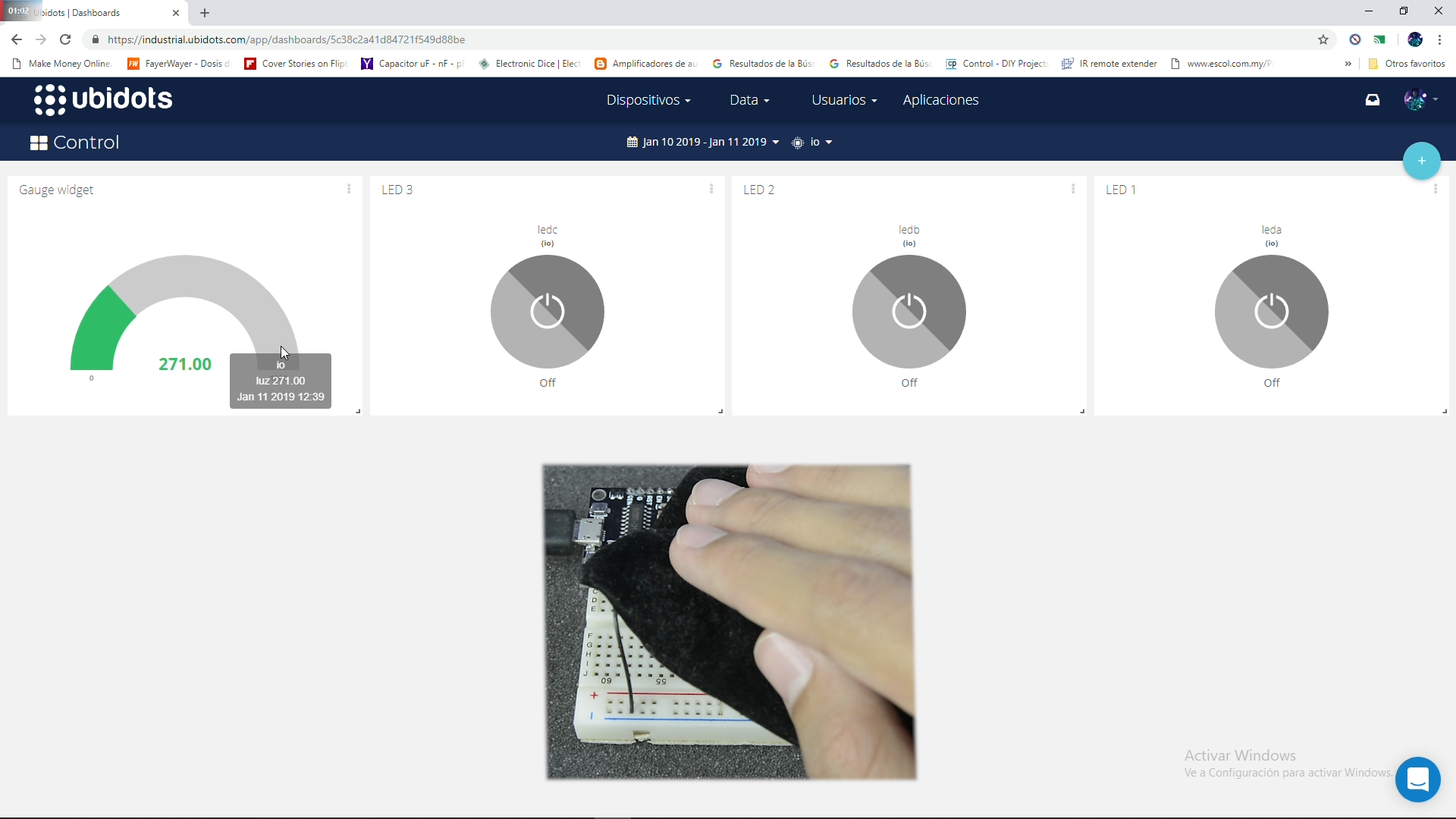
Then create a table, so you can configure the switches and the visualization graphics for the analog lectures.
And test it.
Testing It!
If you any question, be free.
Hope you to enjoy it.