IFTTT Using Photon
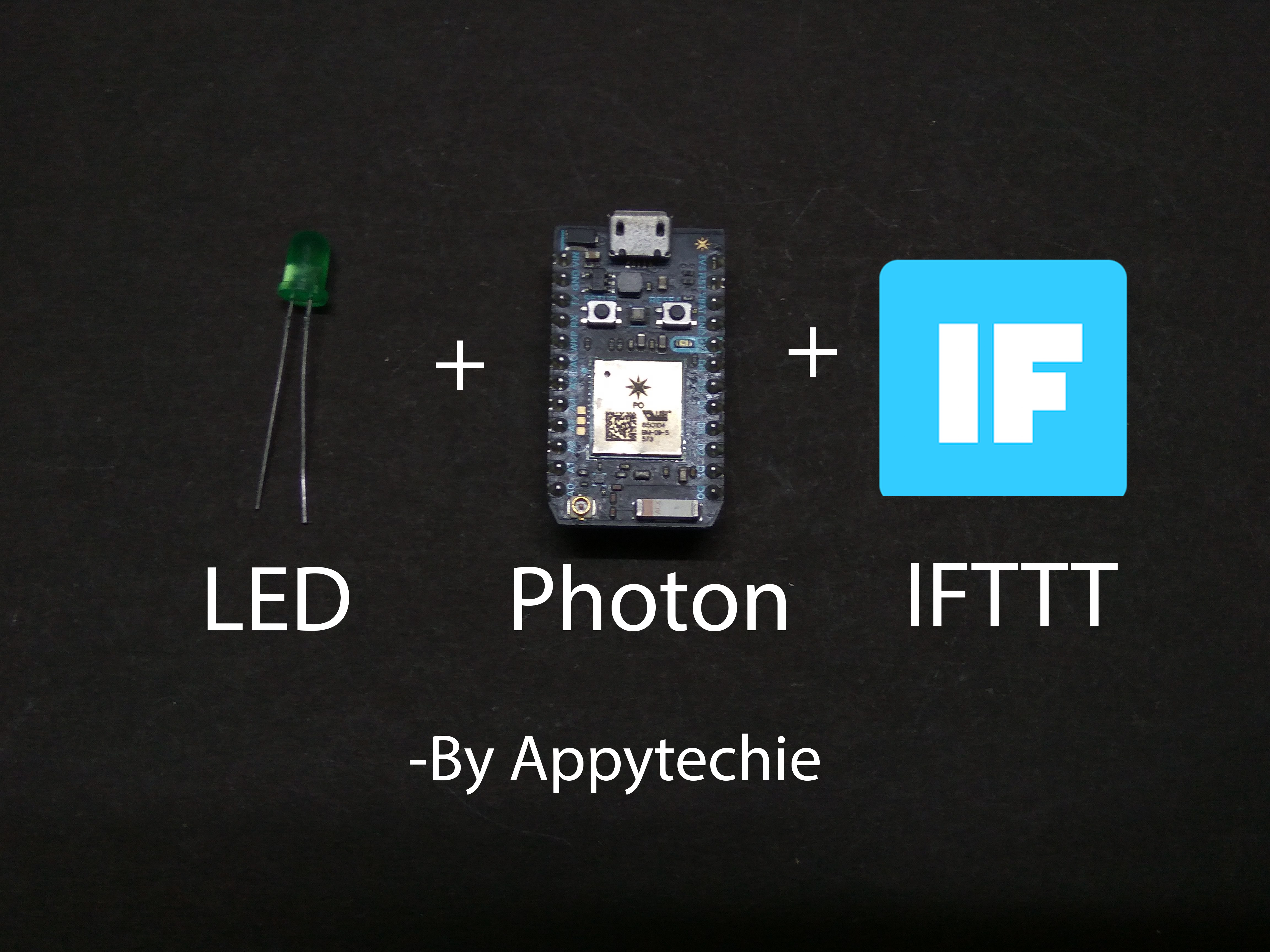
Have you ever wonder having a personal assistant that remind you if there is any notification in activity feed of Facebook and Gmail??Yes?? Then you are at the right place.
Hi !!, I'm Sridhar Janardhan, Today I am writing up an article on the notification of lights when ever there is a detection of any activity feed in your Facebook or Gmail account.
Interesting isn't it??Continue to read.
Let's now start to bill the electronics required.
Components Required:
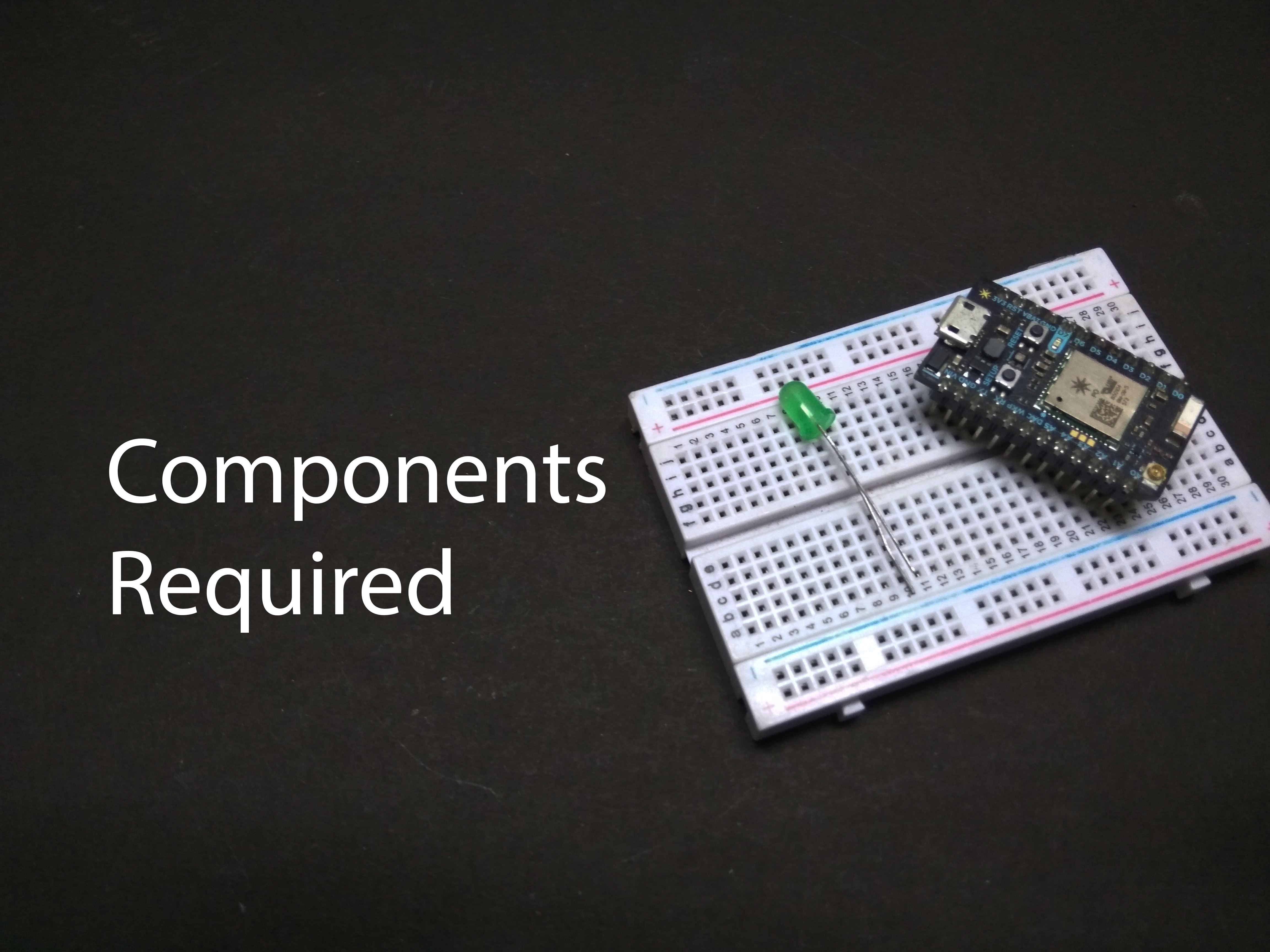
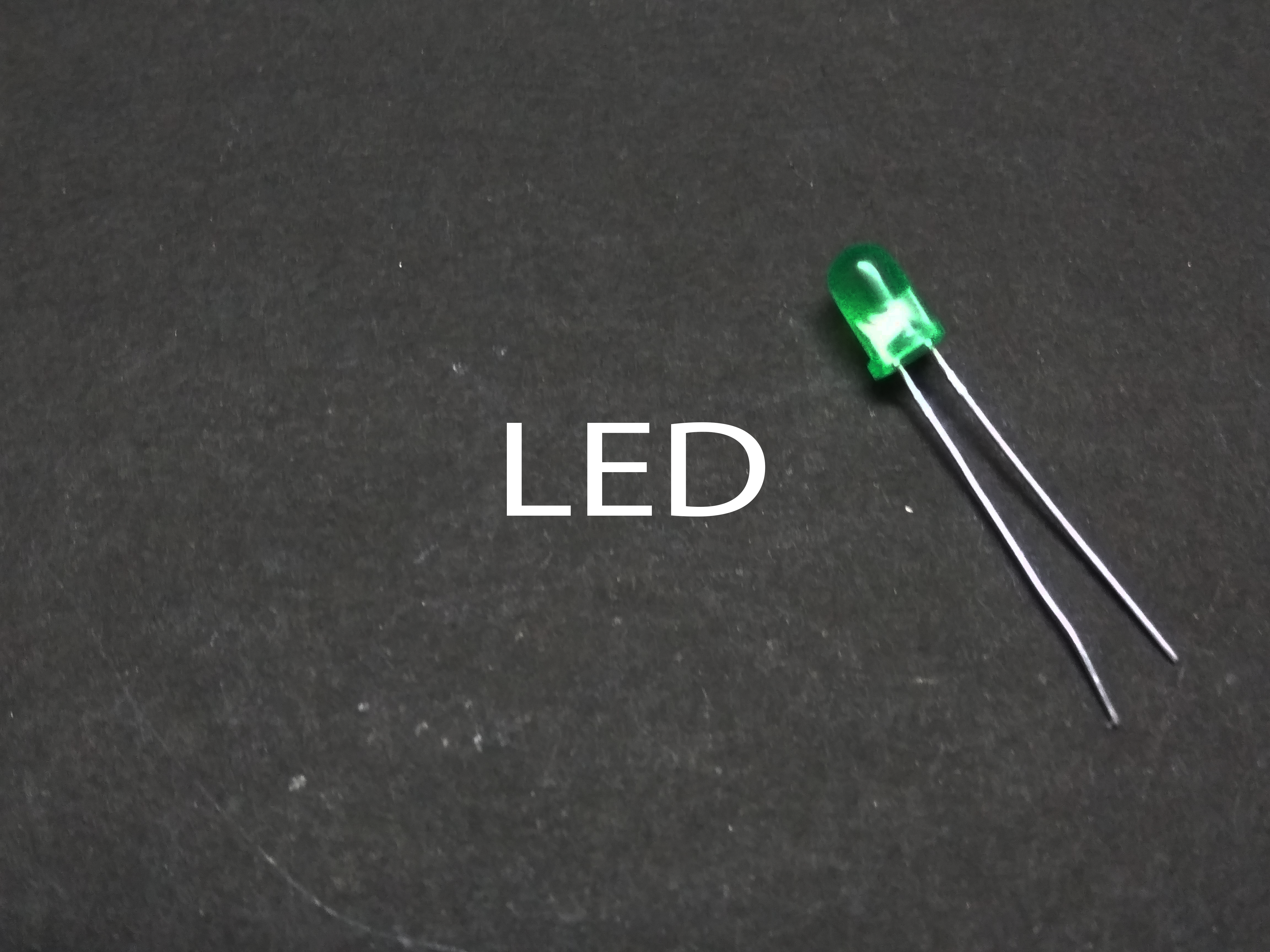
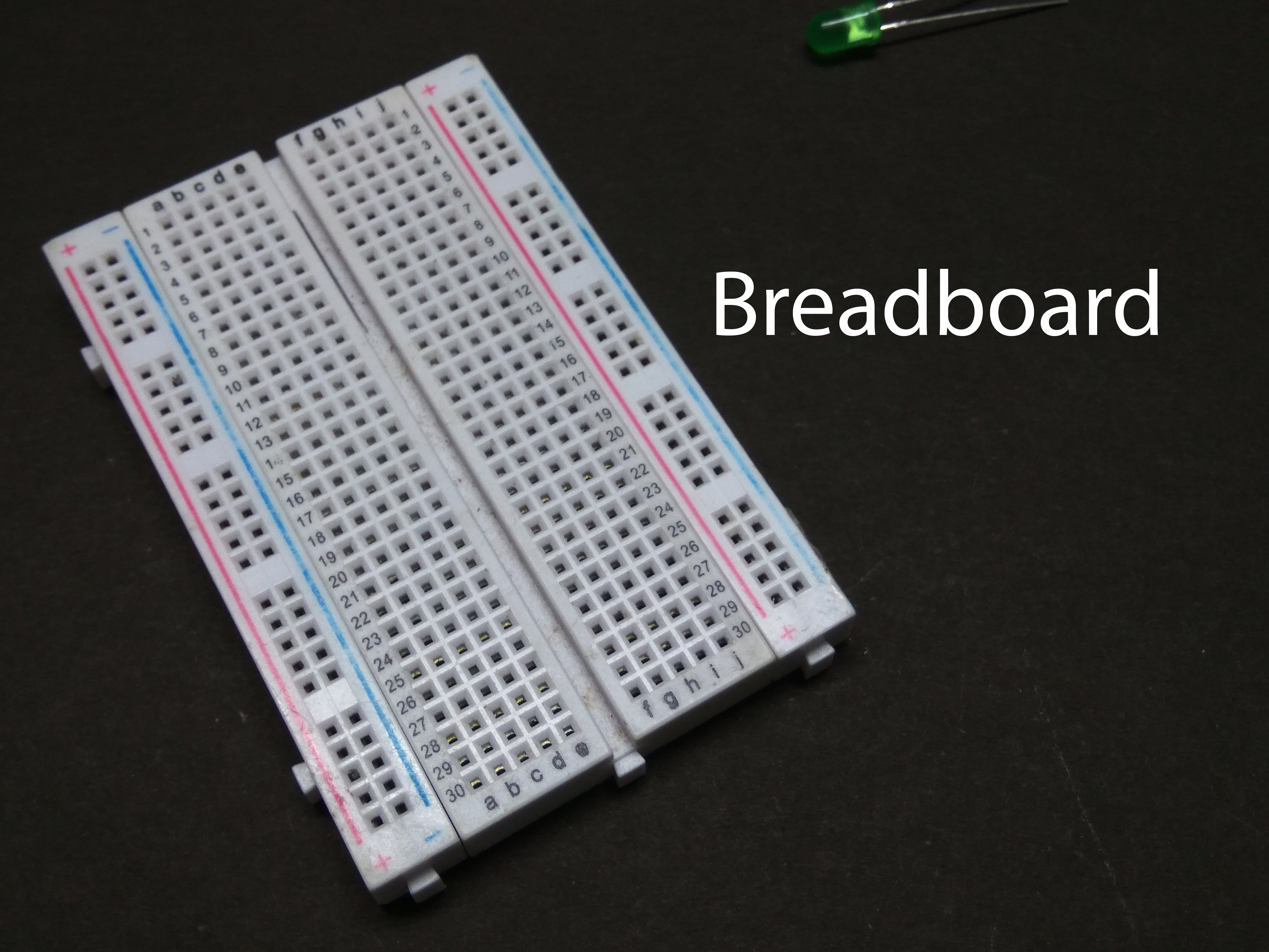
The components and software required for this project are:
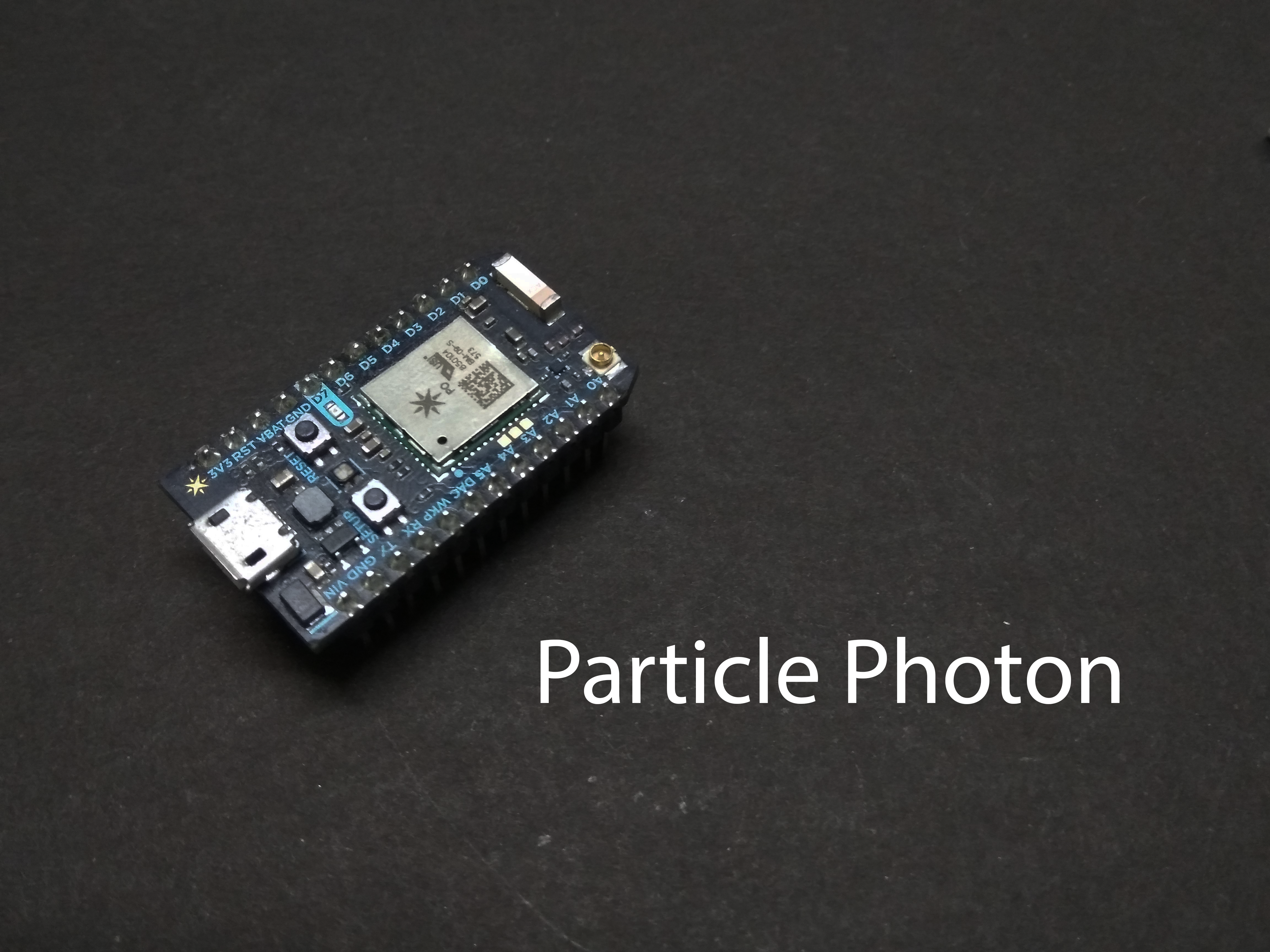
- Particle Photon
- Breadboard
- LED
- Jumper wire
- Particle account
- IFTTT account
Let's get the Photon connected to the wifi
Connecting Photon to the Wifi
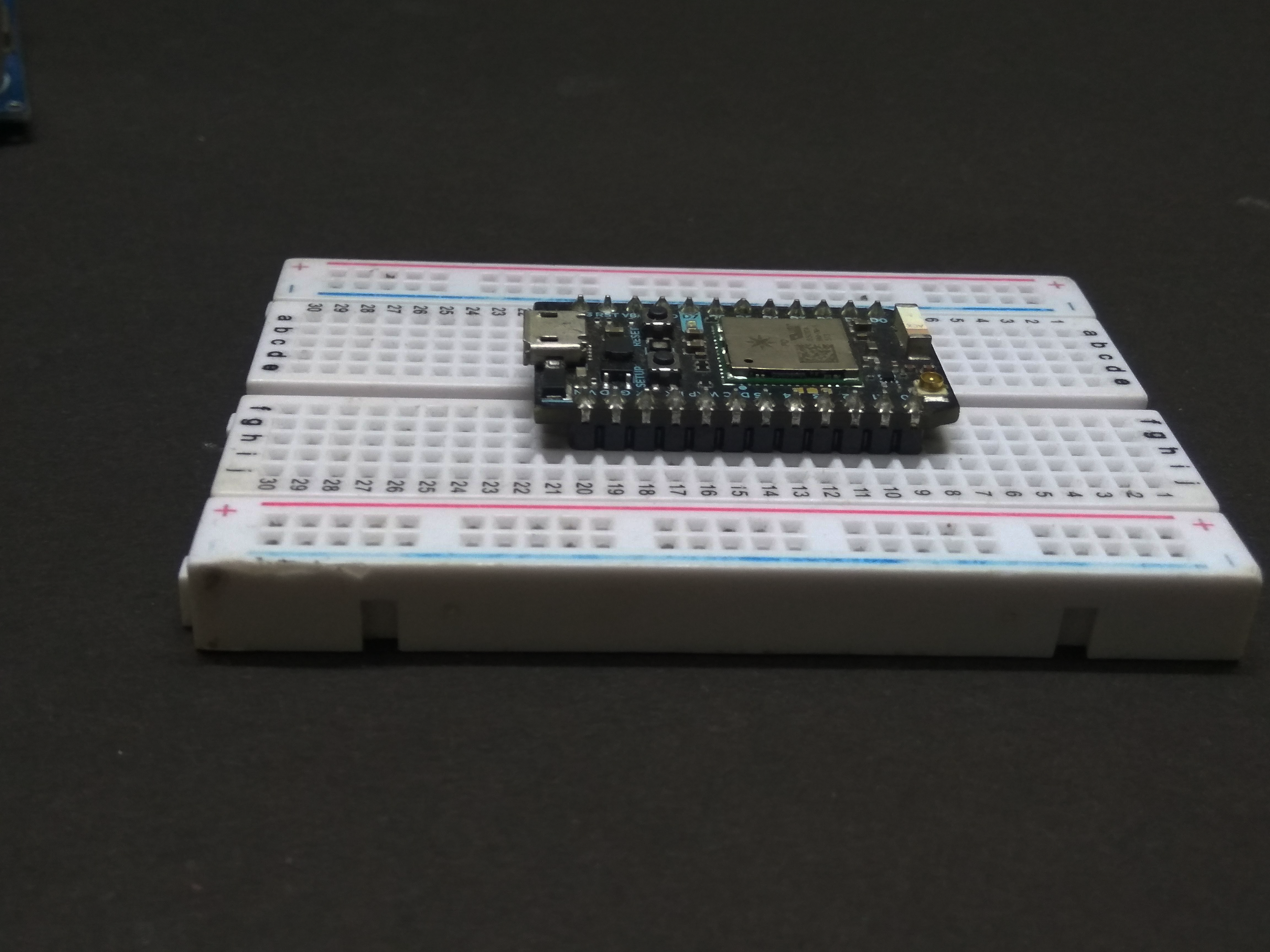
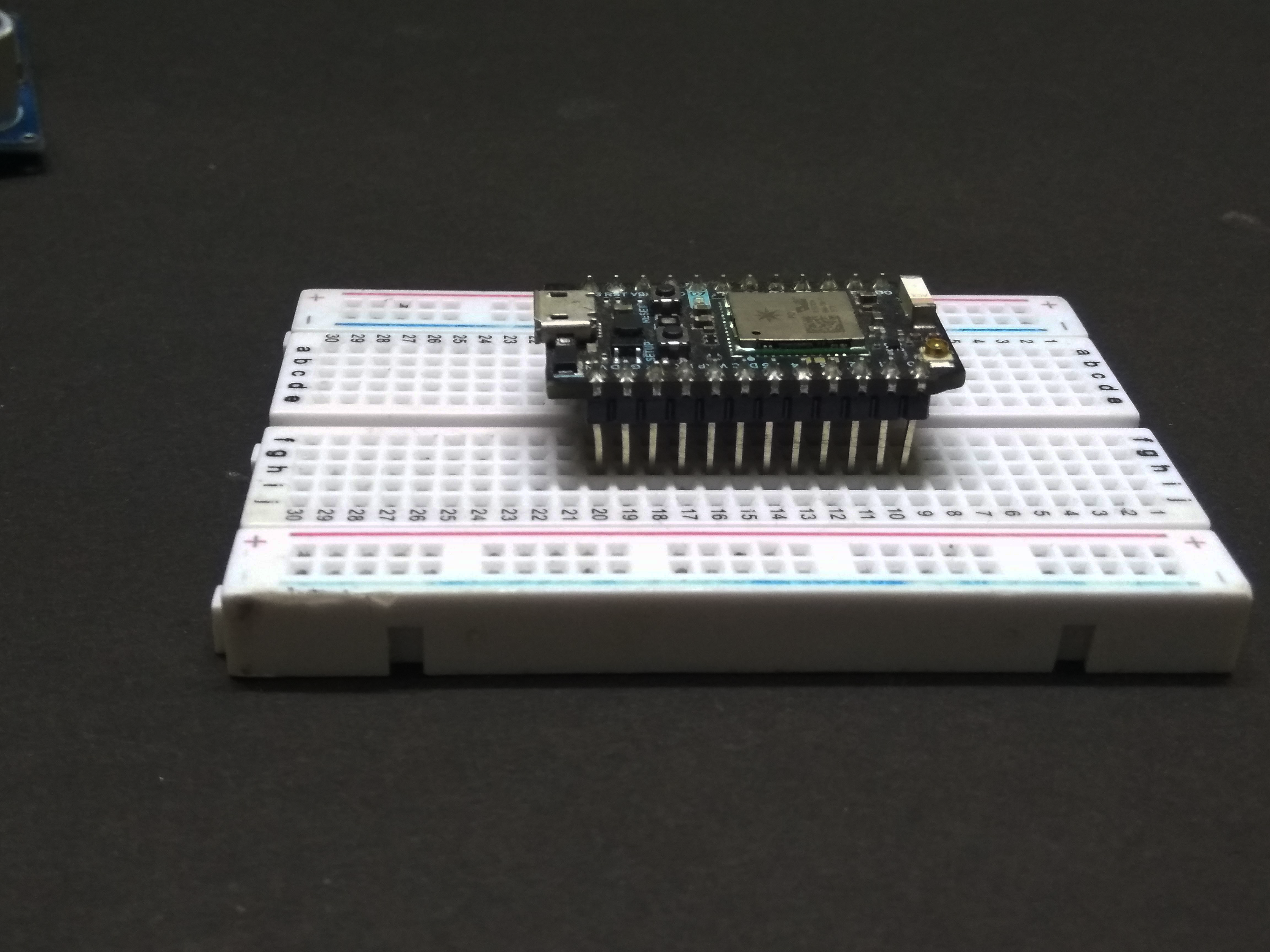
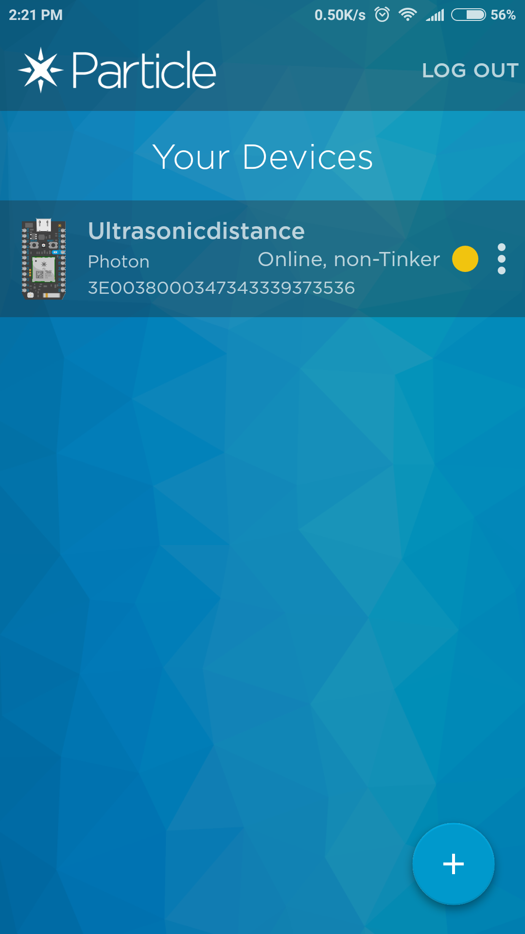
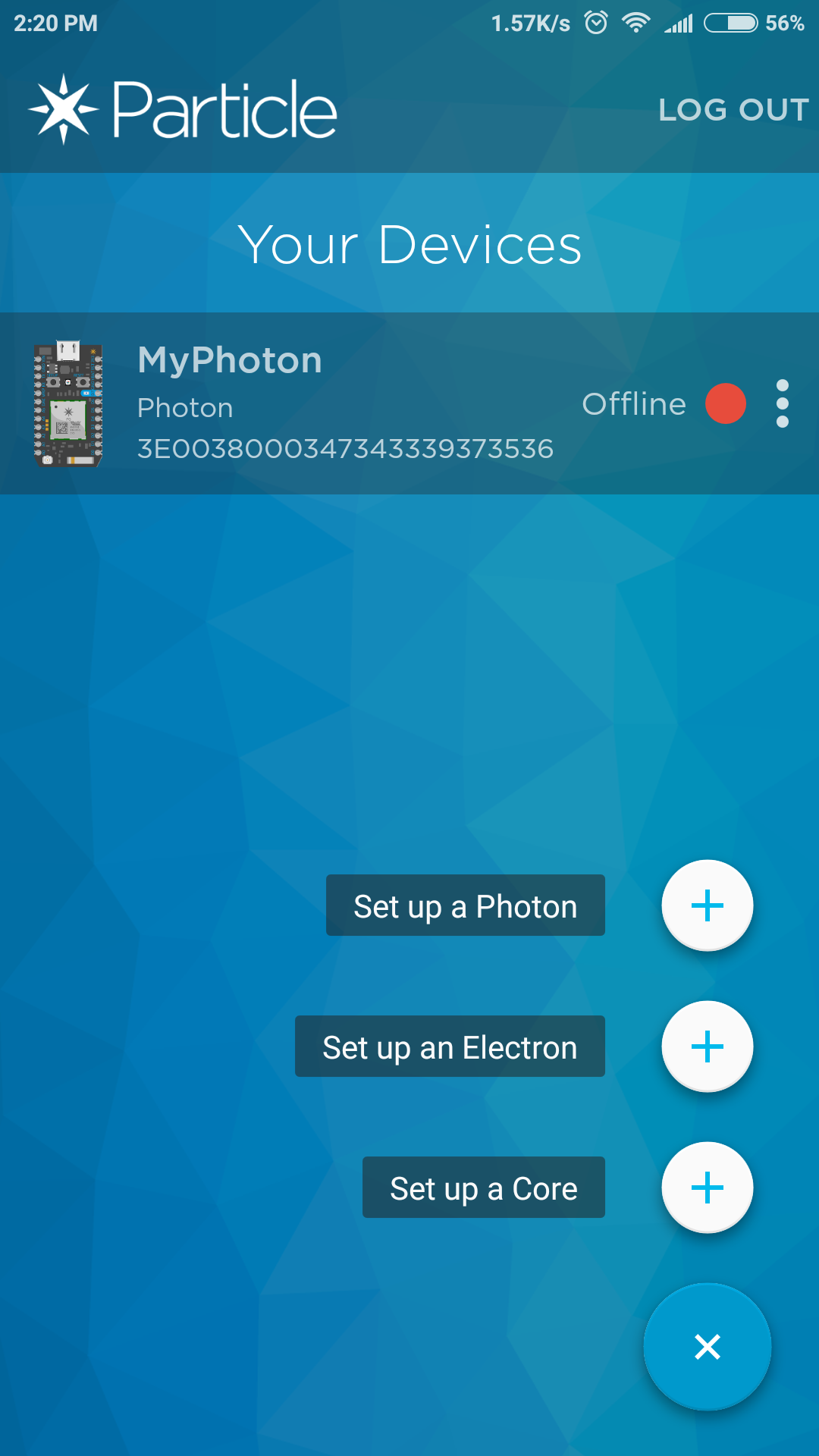
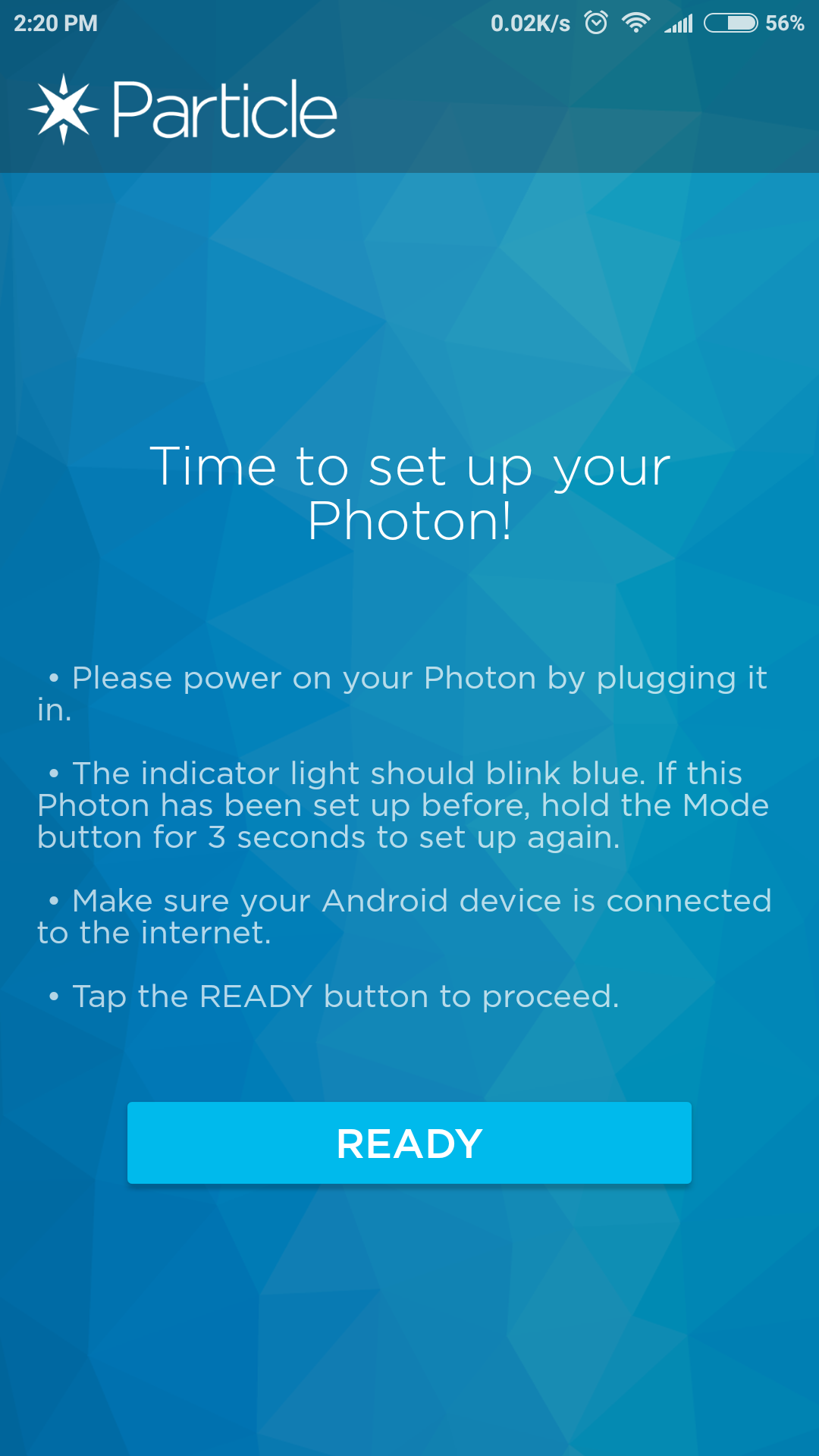
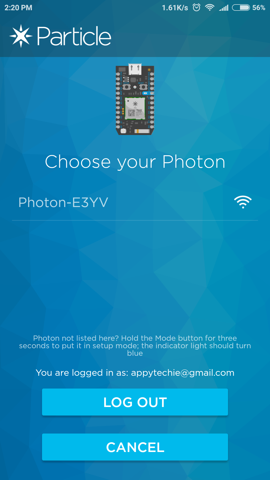
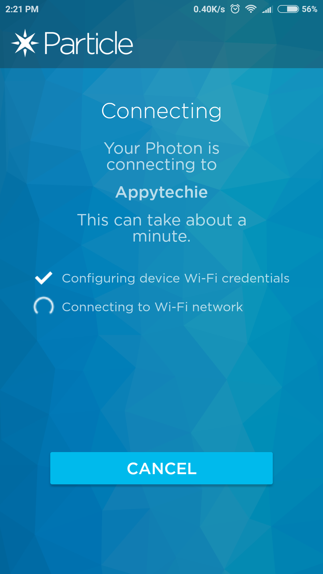
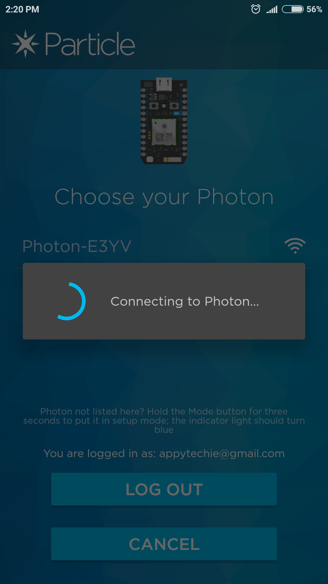
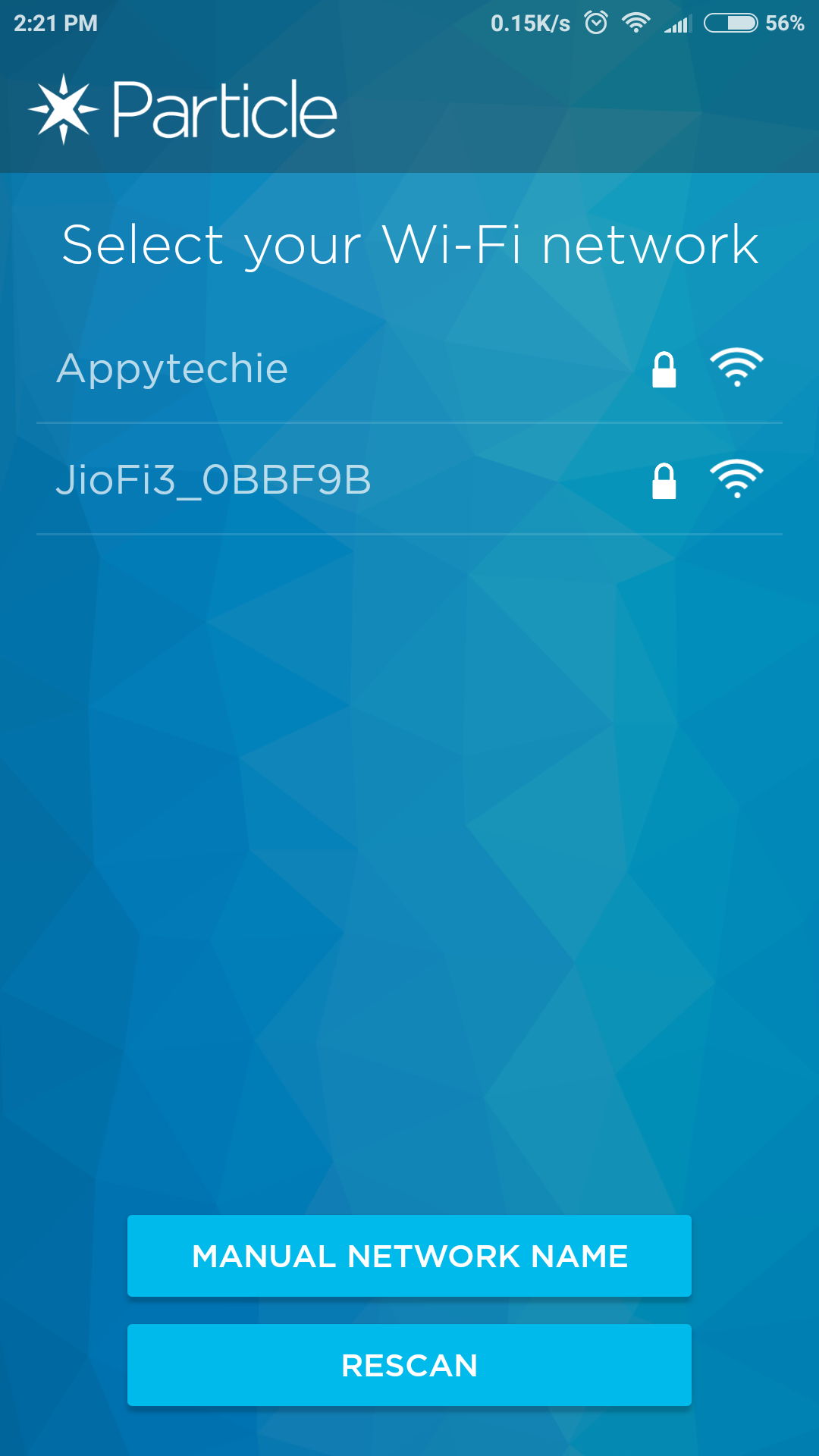
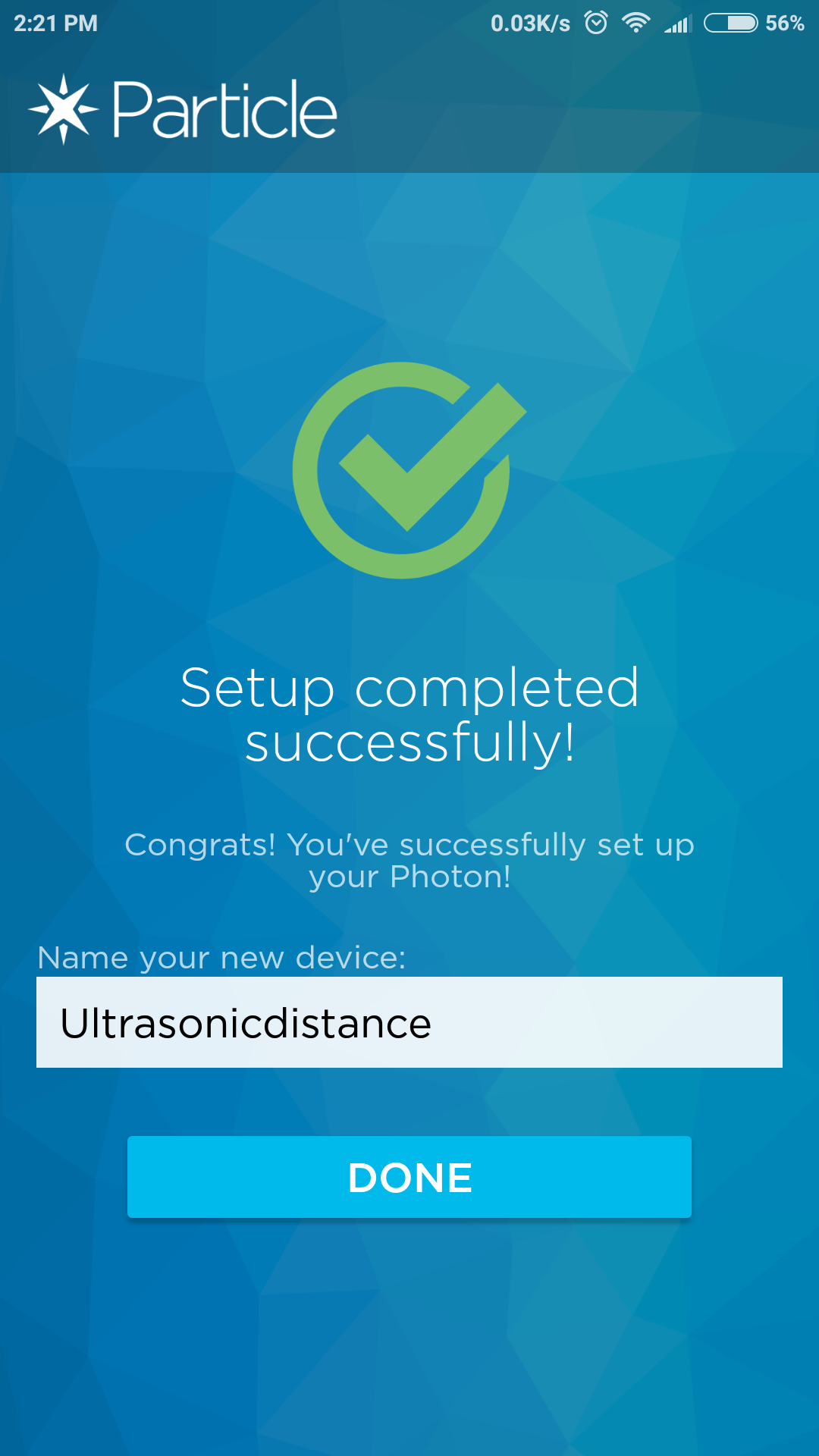
- To connect the Photon to the wifi, Power it up using the USB cable.
- Put the photon to listening mode by pressing the setup button until the led turn Blue color
- Download the Particle app from play store
- Login with your credentials
- Press the '+' button in the bottom right of the screen and choose set up Photon
- Complete the process as per the screen instruction
- Lastly, when you have finished the process successfully you will see the led blinking in Cyan indicating Photon is connected to wifi successfully
Connecting the LED
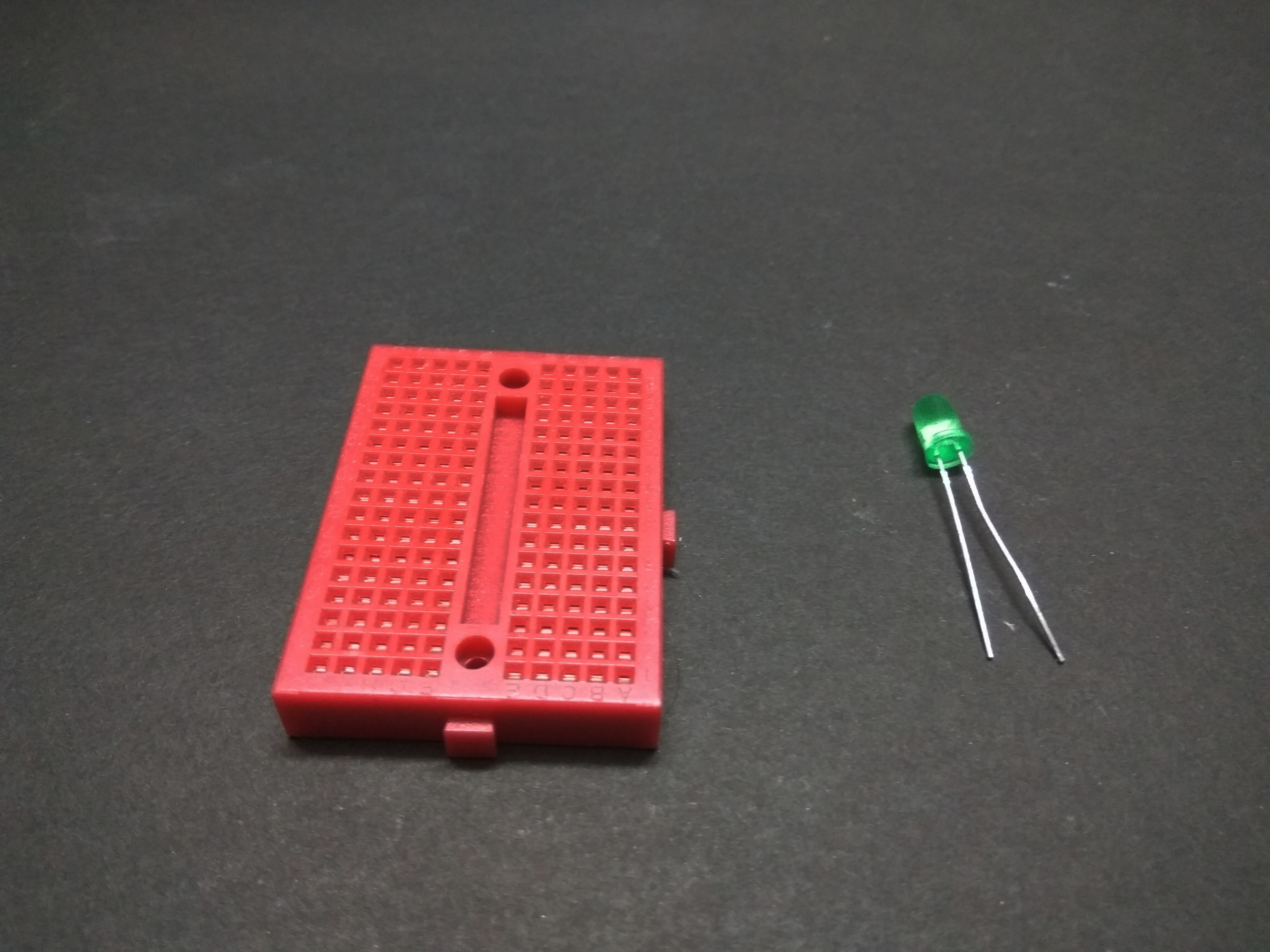
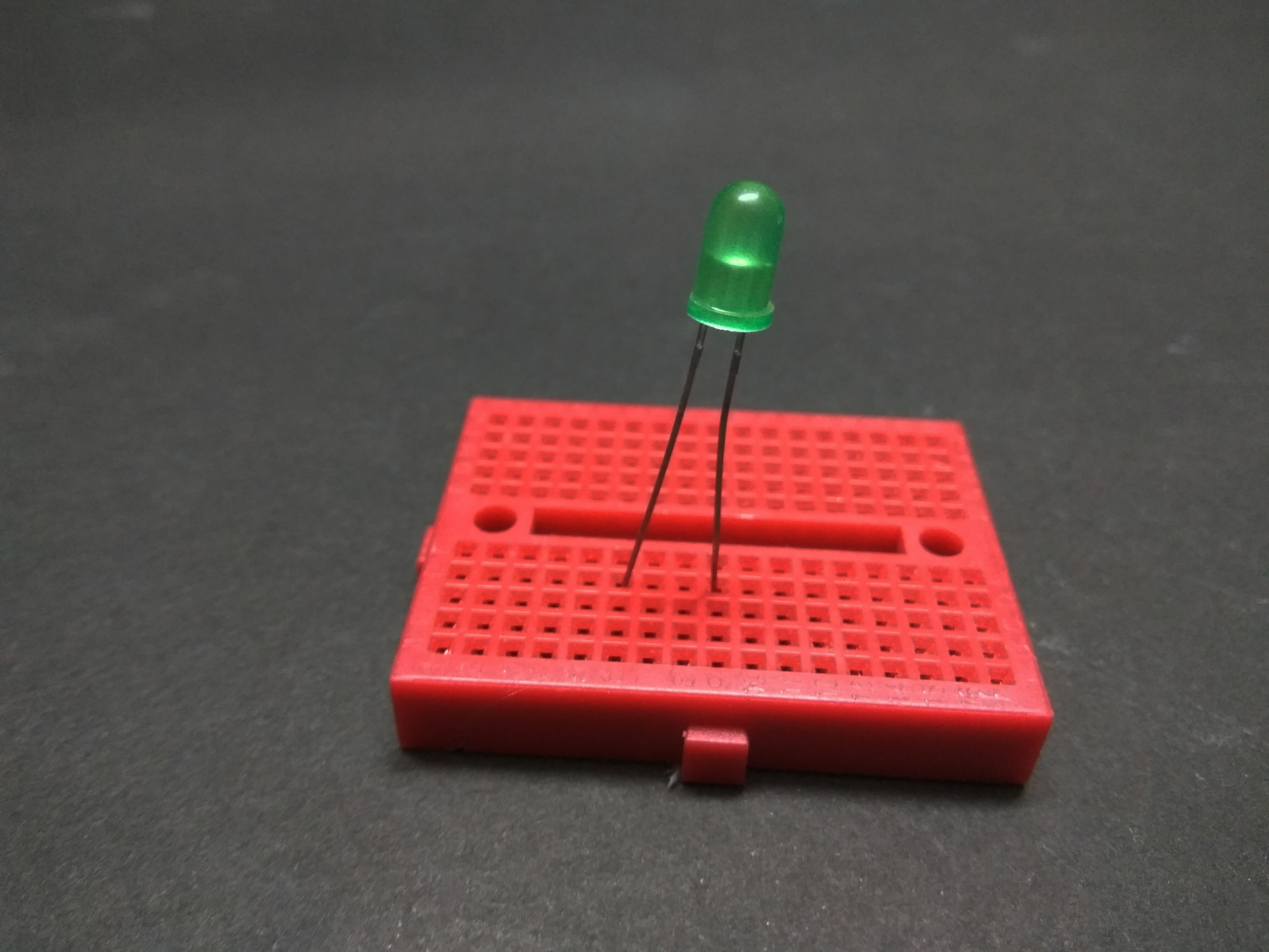
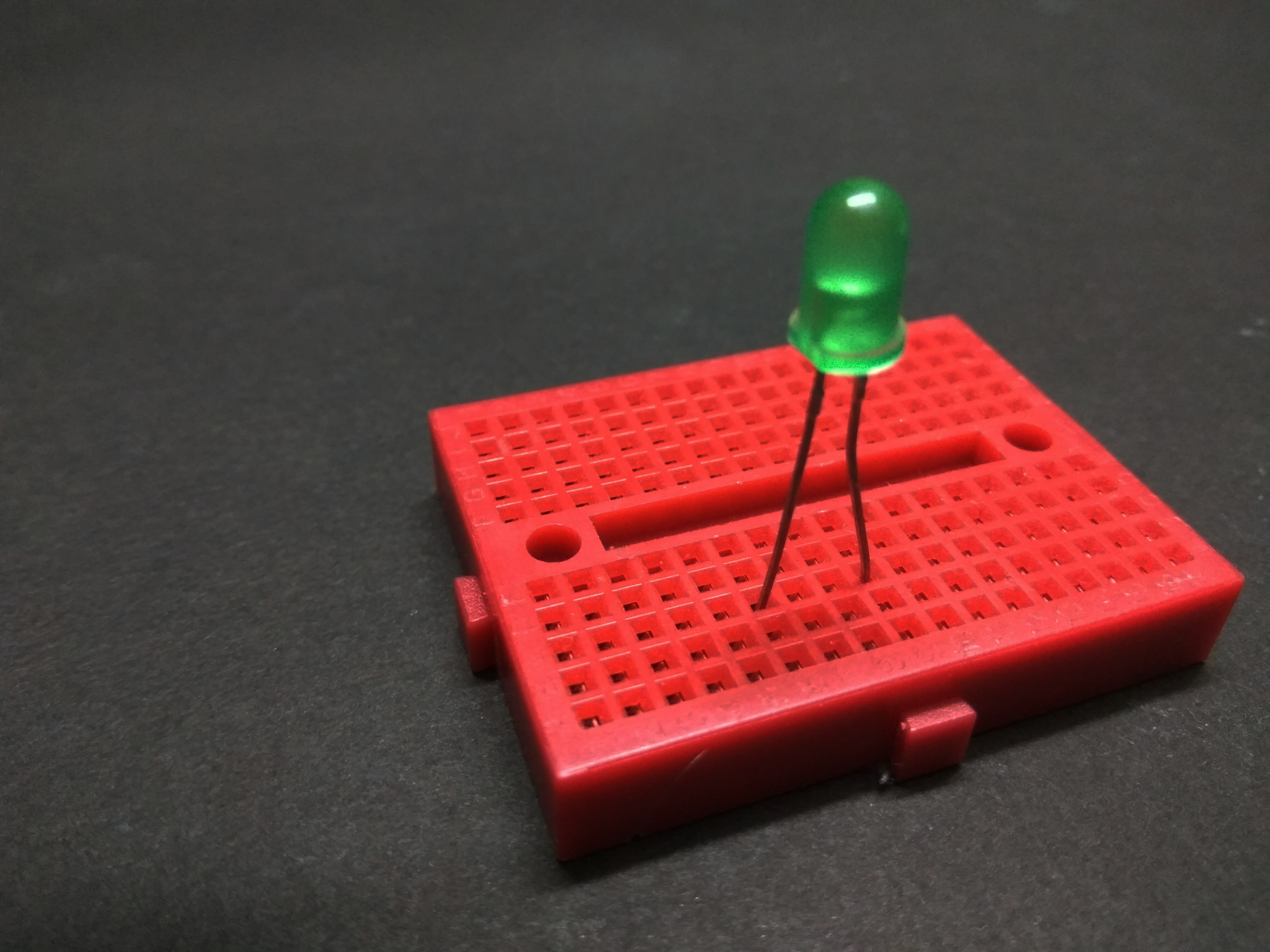
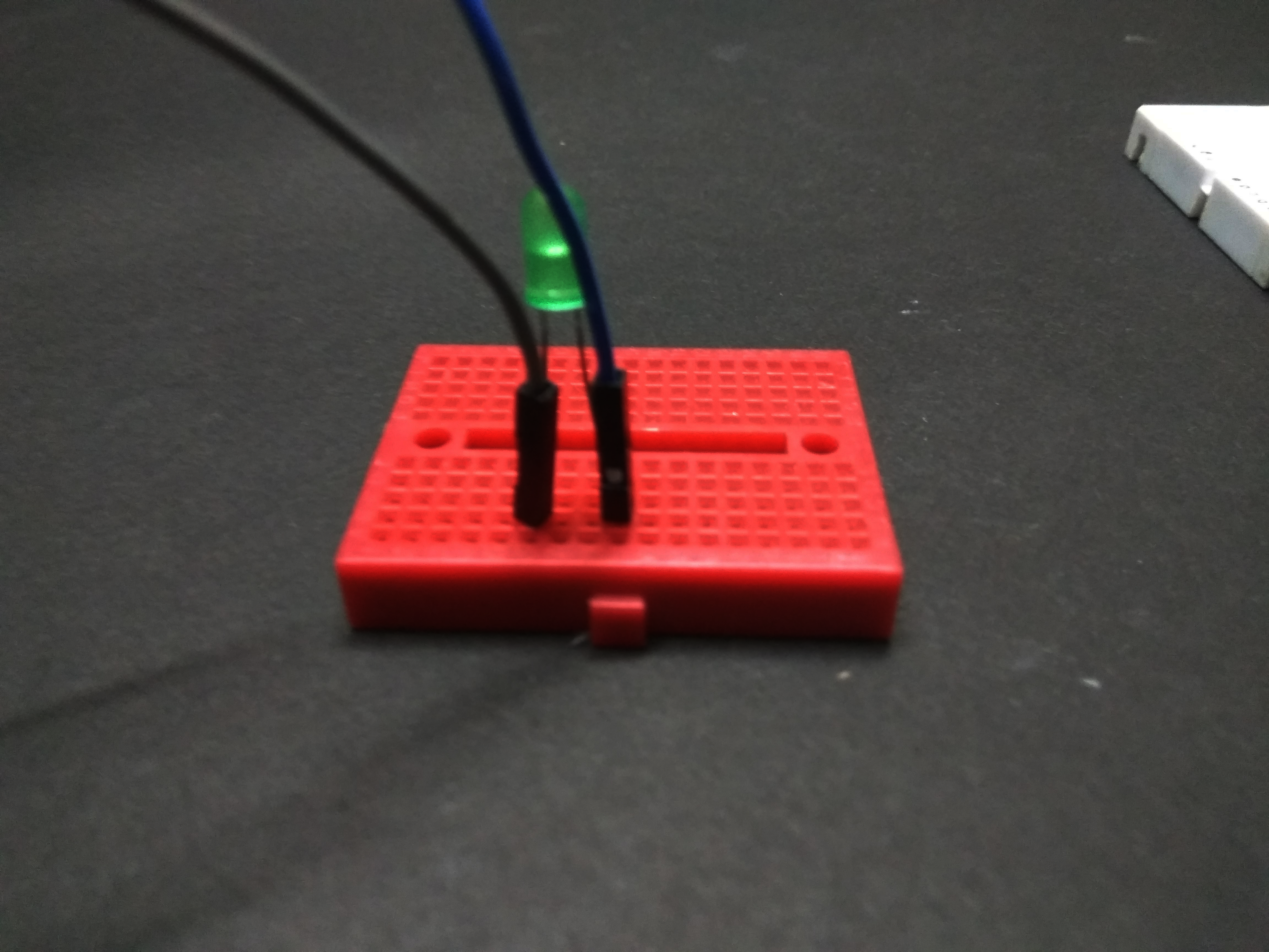
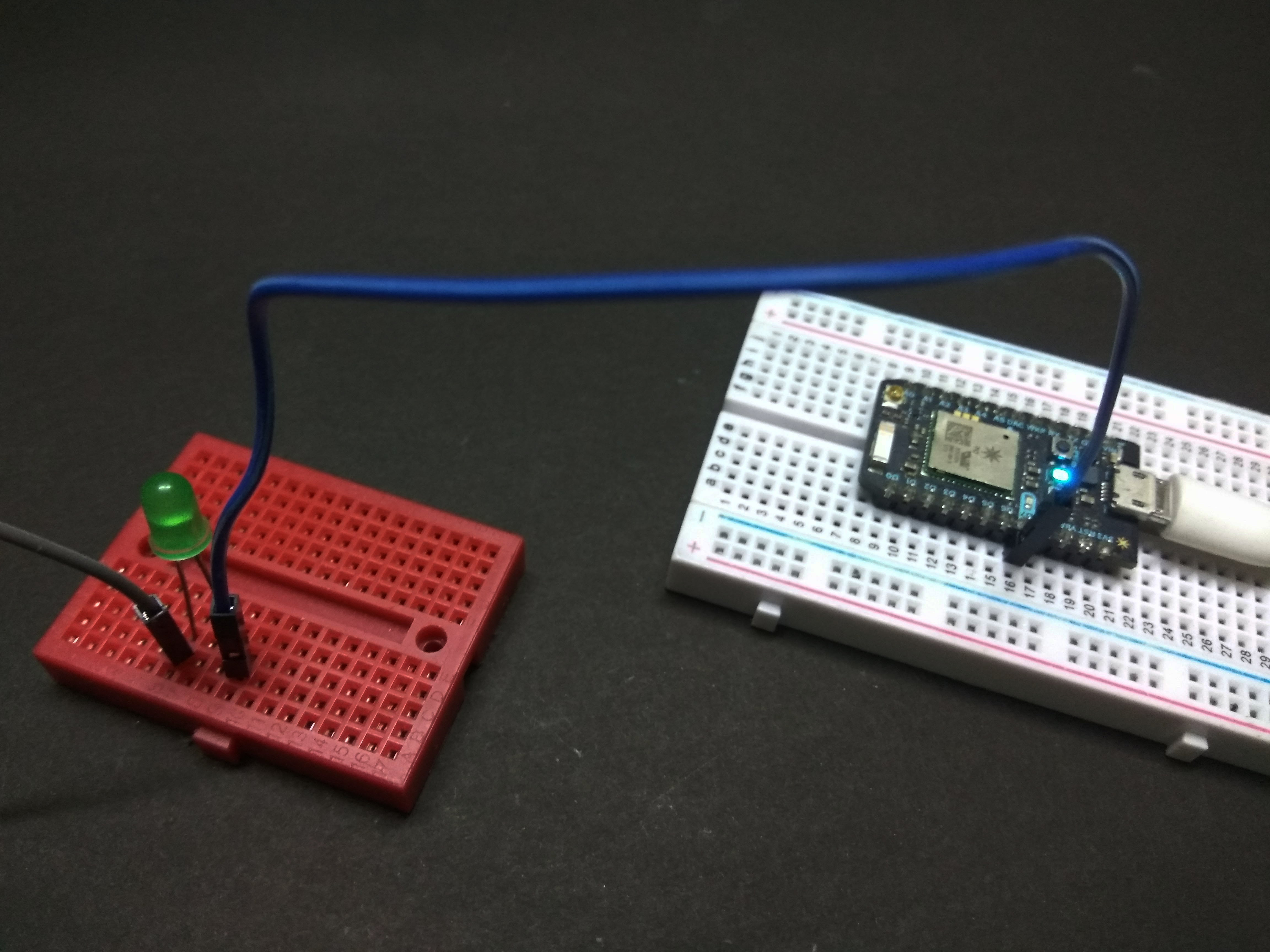

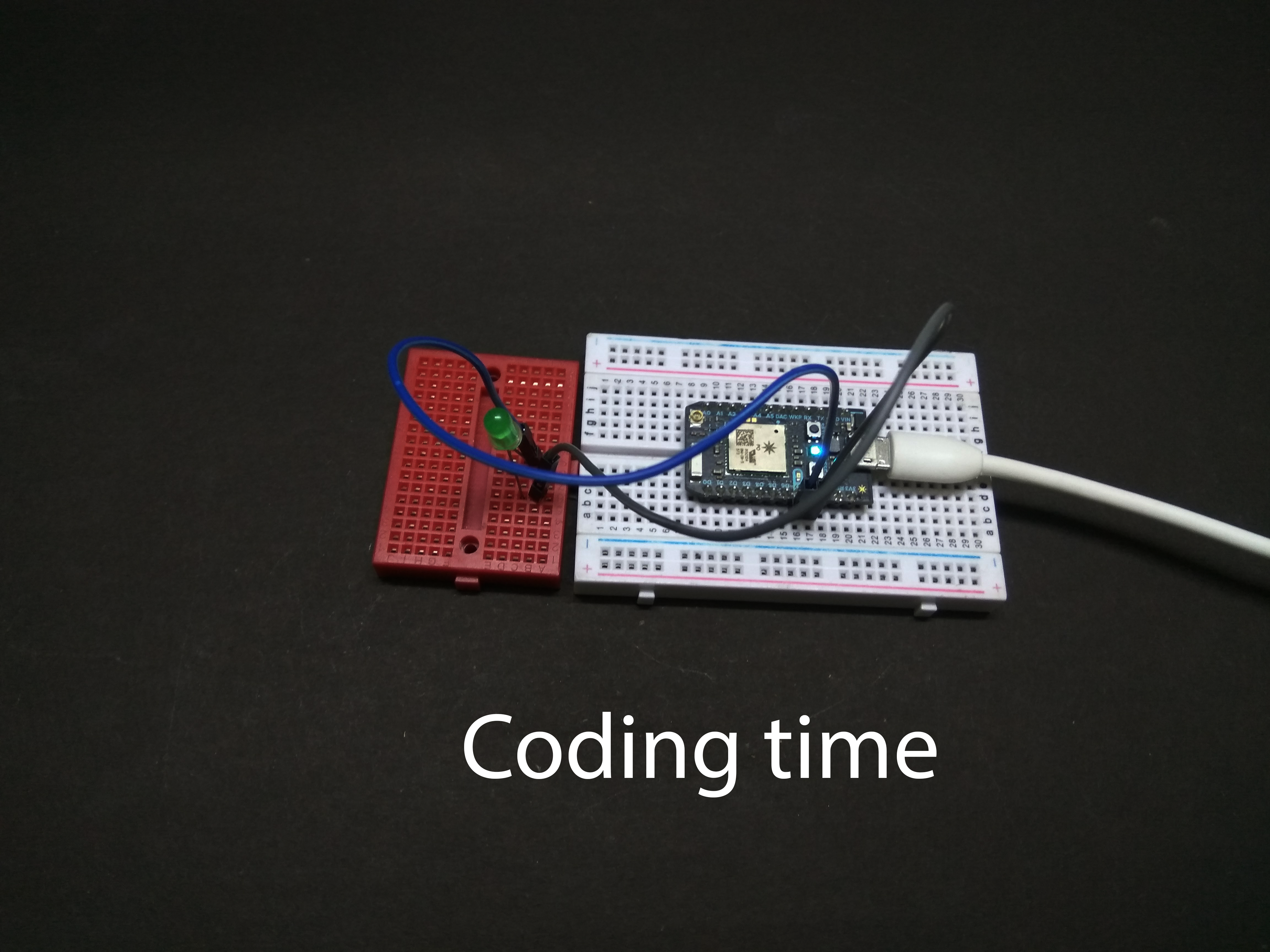
Led has two terminal vary in size the longer leg is called as the positive terminal or anode and the shorter leg is called as negative terminal or cathode.
The connection of two terminals are as follows:
- The positive leg is given to digital pin D7.
- The negative leg is given to negative railing of the breadboard.
IFTTT Account

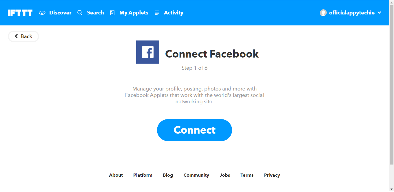
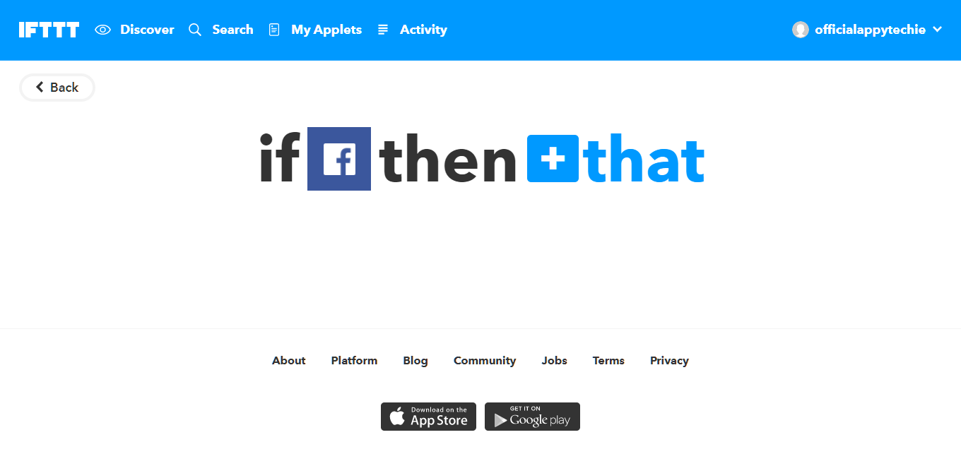
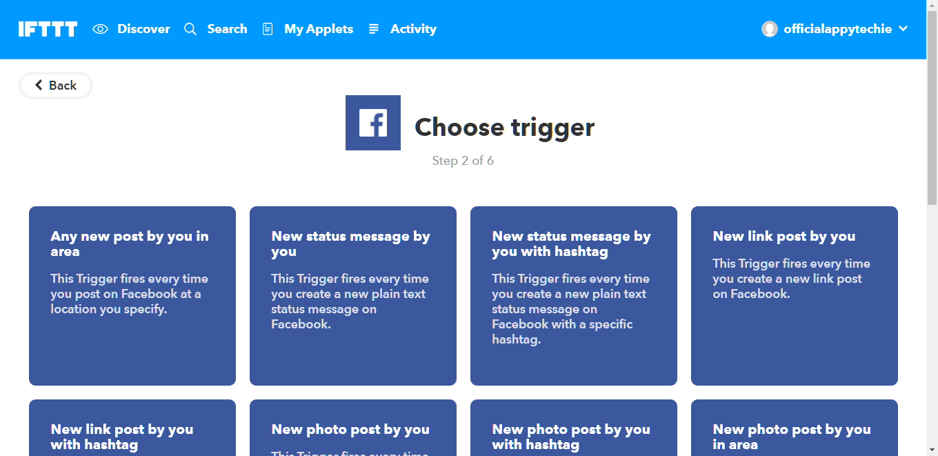
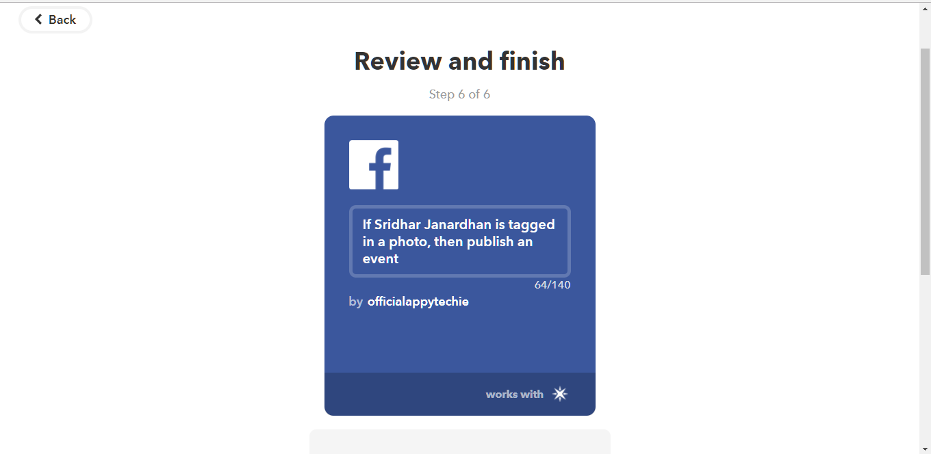
Step by Step Instruction:
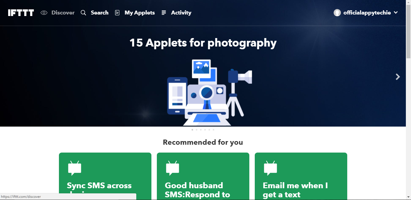
- Go to IFTTT website.
- Login with your credentials
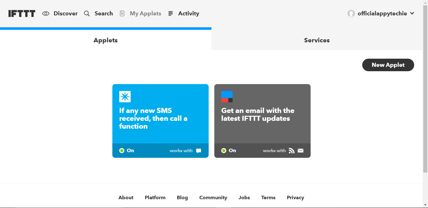
- .Press MyApplets in the navbar.
- Then press new applet.
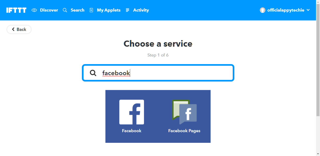
- Then press 'If' in 'If then that'
- Write Facebook in the search query.
- Choose your triggering part.
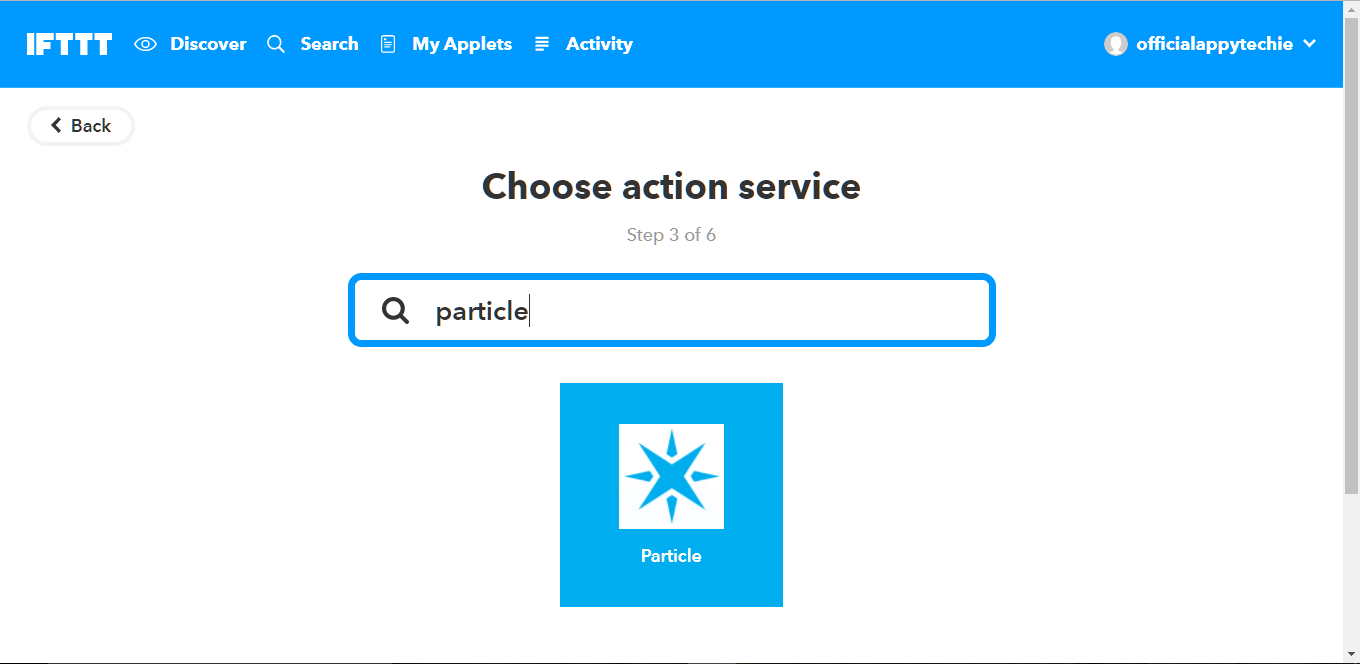
- Then press 'that' in 'If then that'Write Particle in the search query and log in with your particle account credential.
Coding
int led = D7;
void setup(){
//We set the pin mode to output
pinMode(led, OUTPUT); //We "Subscribe" to our IFTTT event called Button so that we get events for it Particle.subscribe("Button", myHandler); } //The program loop, not sure if this has to be here for the program to run or not
void loop() { } //The function that handles the event from IFTTT
void myHandler(const char *event, const char *data){ // We'll turn the LED on
digitalWrite(led, HIGH); // We'll leave it on for 5 second...
delay(5000); //Then we'll turn it off...
digitalWrite(led, LOW); }
Output
