IBM Cloud Robot



Motivation
I work as a robotics teacher in Sydney. I want to introduce my AI robot to my students in my class next month. In addition, I'm joining NASA Open Innovation Initiative (also known as NASA Space Apps Challenge) with my AI robot to measure the space environment such as temperature, humidity, and pressure. So, I'm so excited!!
Introduction
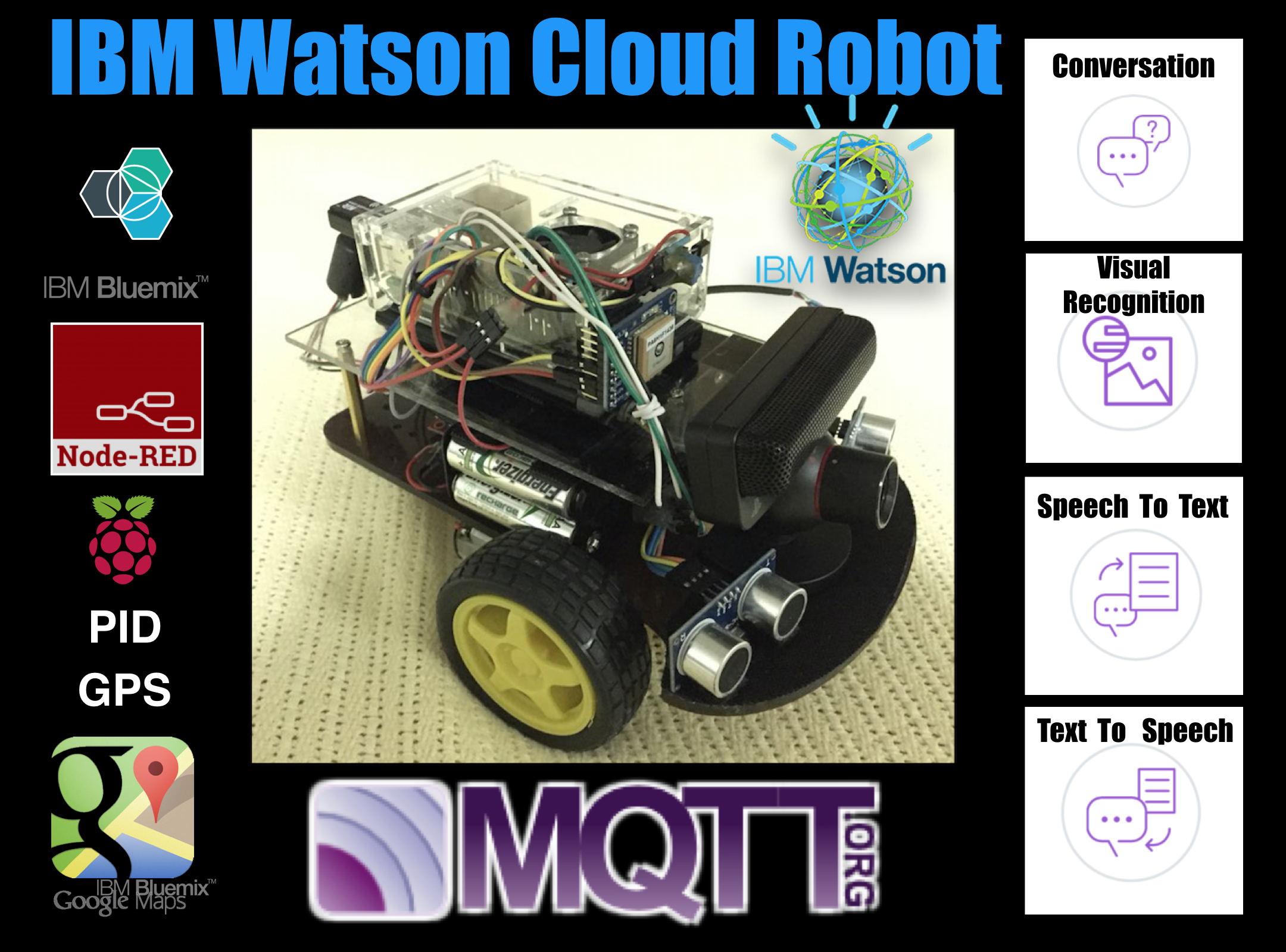
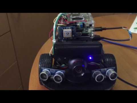
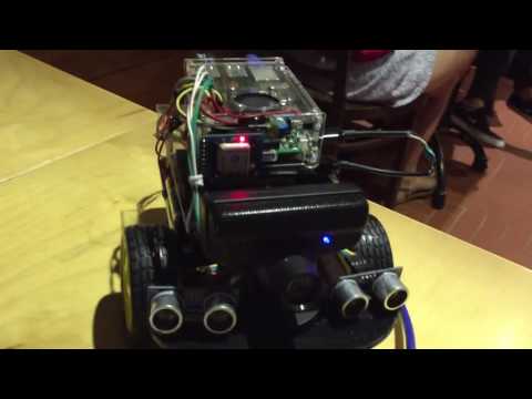
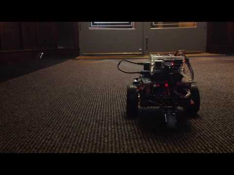
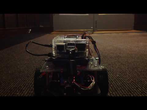
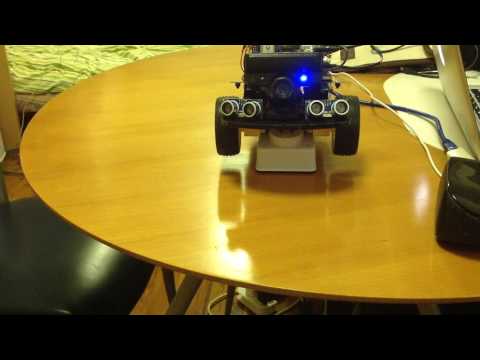
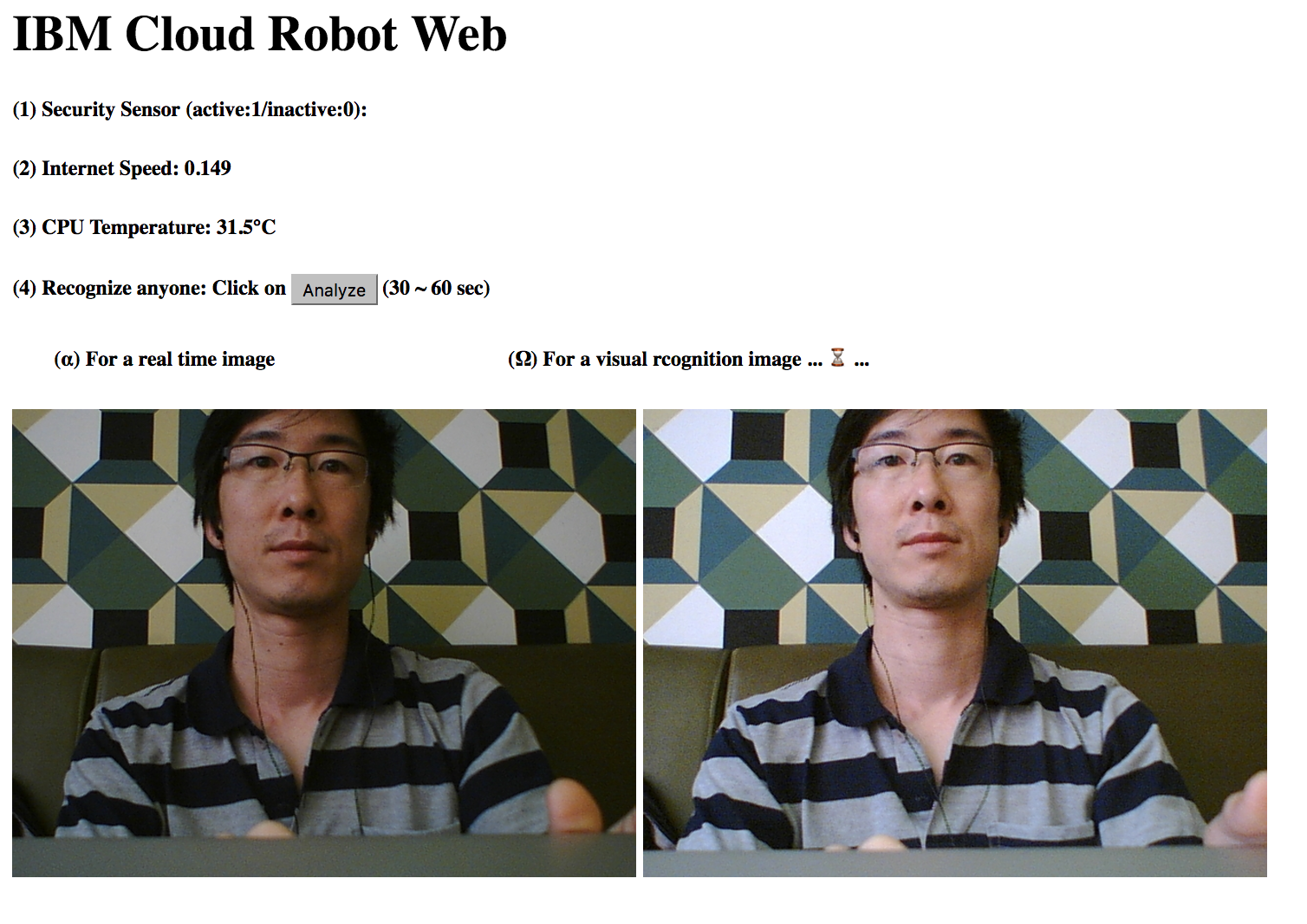
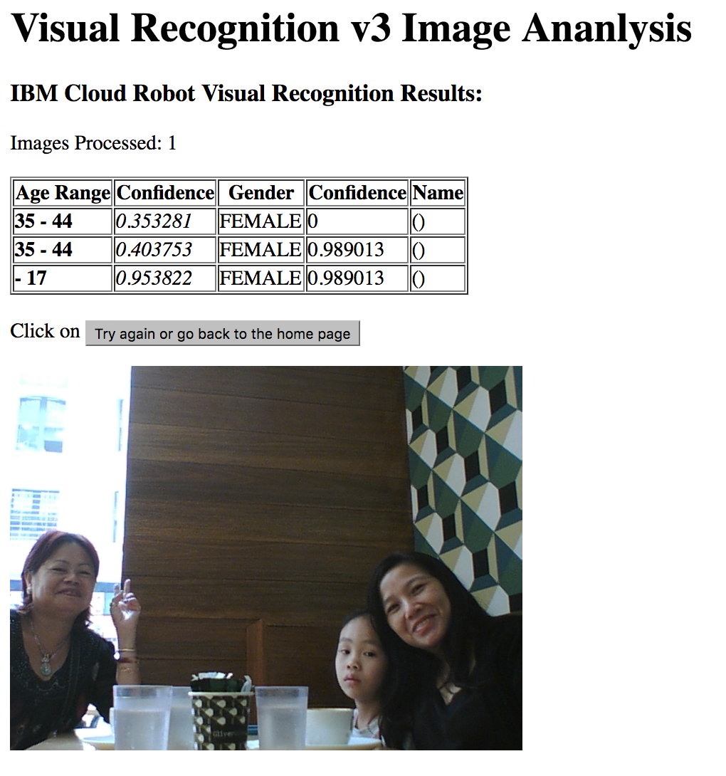
The IBM Watson Cloud Robot can recognize a human face, voice, and text like a human. The robot clearly recognized the celebrity (Elon Musk) and who he was. Also, it recognized my voice & any text. (YouTube)
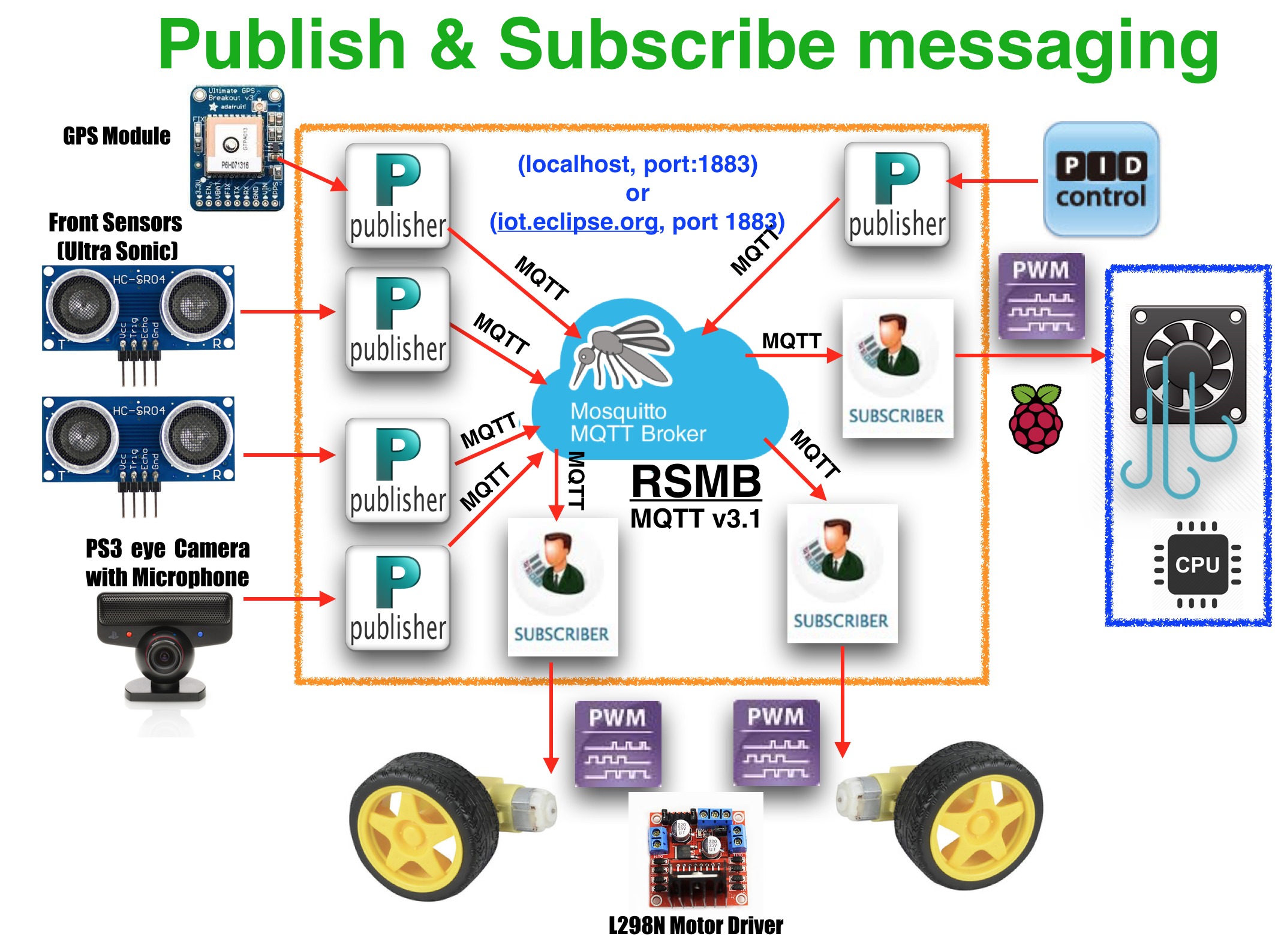
This instructable will cover the basic steps that you need to follow to get started with open sources such as Watson nodes (Visual Recognition V3, Speech To Text, Text To Speech) for IBM Bluemix, Node-RED, MQTT v3.1. MQTT(Message Queueing Telemetry Transport) is a Machine-To-Machine(M2M) or Internet of Things (IoT) connectivity protocol that was designed to be extremely lightweight and useful when low battery power consumption and low network bandwidth is at a premium. It was invented in 1999 by Dr. Andy Stanford-Clark and Arlen Nipper and is now an Oasis Standard .
- How to tune PID gains of Node-RED with MQTT on Raspberry Pi:
https://www.instructables.com/id/PID-Control-for-CPU-Temperature-of-Raspberry-Pi/
- How to use the Bluemix platform (Docs)
https://console.ng.bluemix.net/docs/
- Enclosed my additional material (Pi-Scratch_Robot_GPIO.sb) for kid education at Download List
(Functions: Driving motors & Taking a picture on Rasberry Pi)
Table of Contents
Step 0: Introduction
Step 1: Table of Contents
Step 2: Bill of Materials
Step 3: Assembly (Wiring & Soldering)
Step 4: Programming NodeRED on Raspberry Pi2
Step 5: Setting up MQTT v3.1 on Raspberry Pi2
Step 6: Checking your NodeRED codes with MQTT on Raspberry Pi2
Step 7: Adding & Setting up PID node, Dashboard on Raspberry Pi2
Step 8: Configuring the PS3 EYE camera with microphone
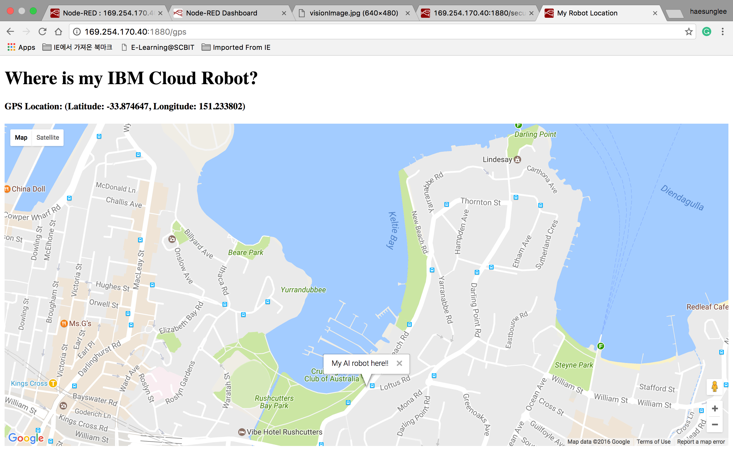
Step 9: Configuring GPS Sensor
Step 10: Using a dashboard for the robot
Step 11: Tuning PID controller
Step 12: (Optional) Programing a Pi-Scratch Robot
Step 13: Download list
Step 14: List of references
Step 15: Version Note
Bill of Materials
- Raspberry Pi3 Kit X 1ea
- Pi-1,2,3 are Possible.
- Installation guide
- Download image files
- Installing VNC : You can connect Raspberry Pi2 with Macbook Pro or Windows.
-
Sony PlayStation Eye Camera (embedded a microphone) X 1ea
- Raspberry Pi's box with Fan X 1ea
- PNP A1015 Transistor X 1ea
- Adjustable resistor(102) X 1ea
- Jumper wires(1m) X 1ea
- Wifi dongle X 1ea
- Description
- If you have Pi-3, it's unnecessary.
- Android smartphone's portable battery X 1ea
- Nod-RED software X 1ea
- Free open source
- Use the version pre-installed in Raspbian Jessie image since November 2015
- Installation guide
- MQTT v3.1 software X 1ea
- Free open source
- Installation guide includes at the Step
- Places to buy from?
- Element14
- Adafruit
- DigiKey
- Sparkfun
- eBay
- Amazon
Assembly (Wiring & Soldering)
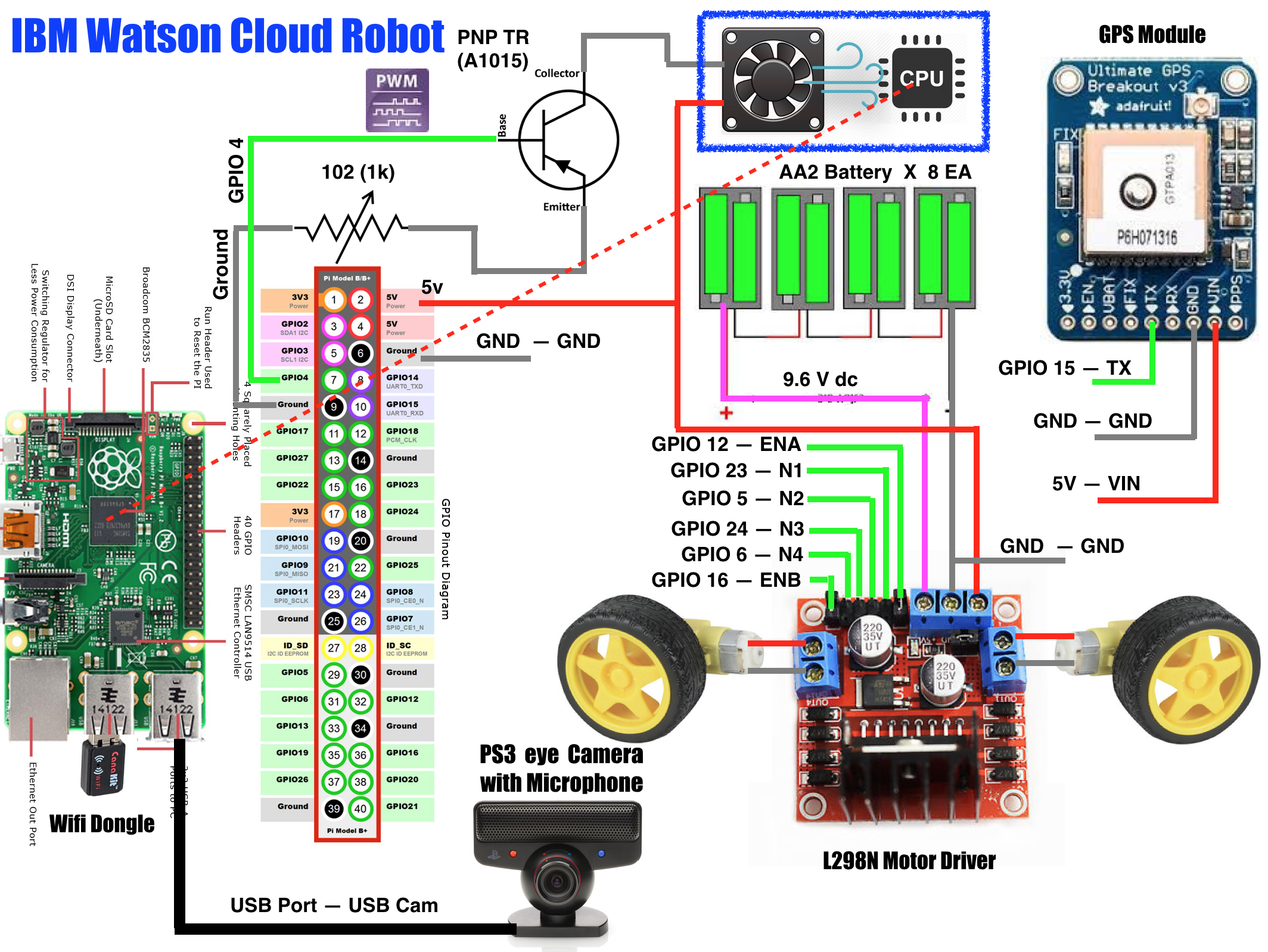
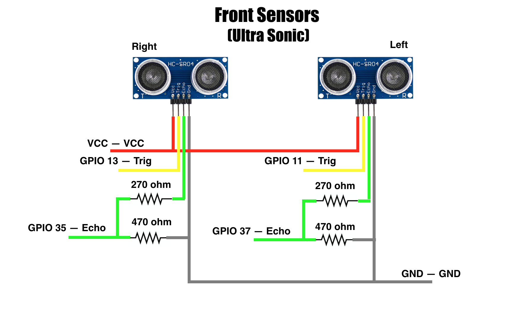
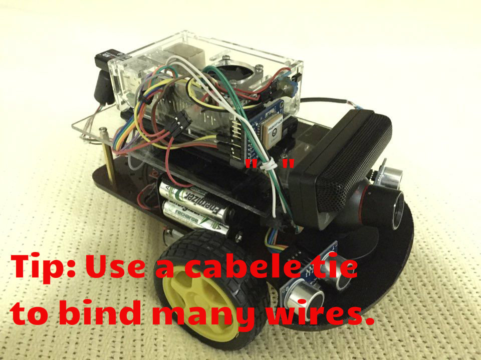
Programming NodeRED on Raspberry Pi2
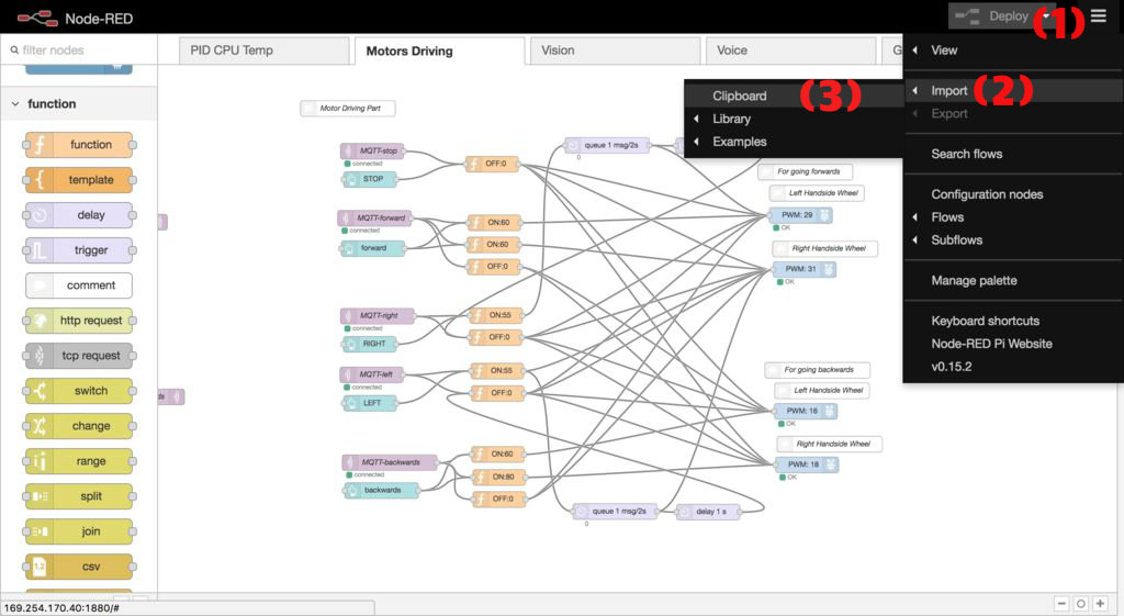
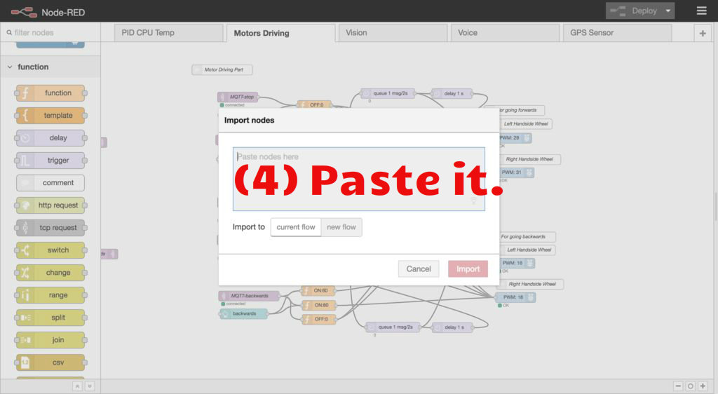
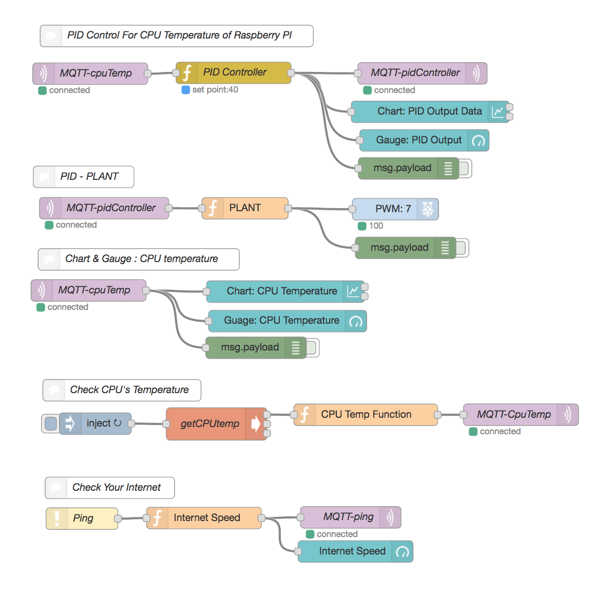
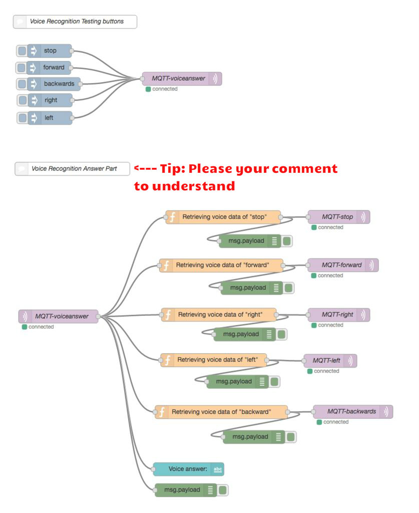
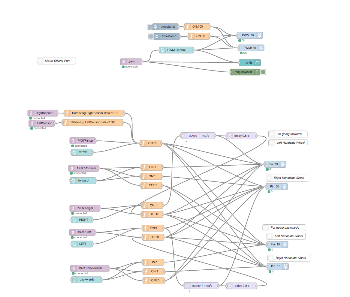
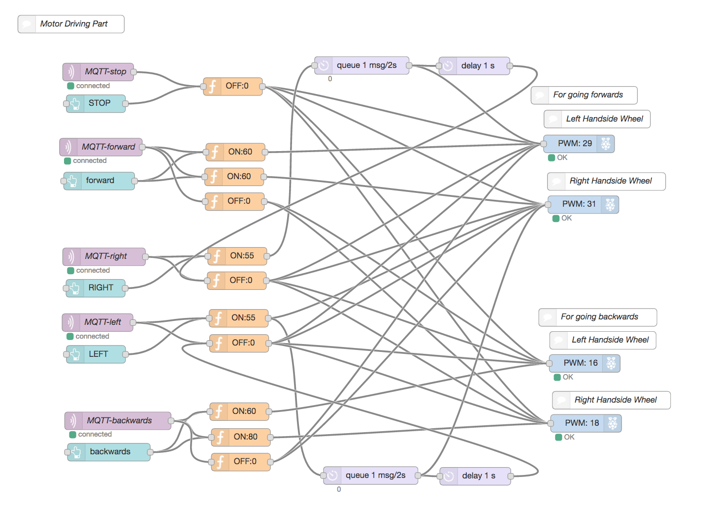
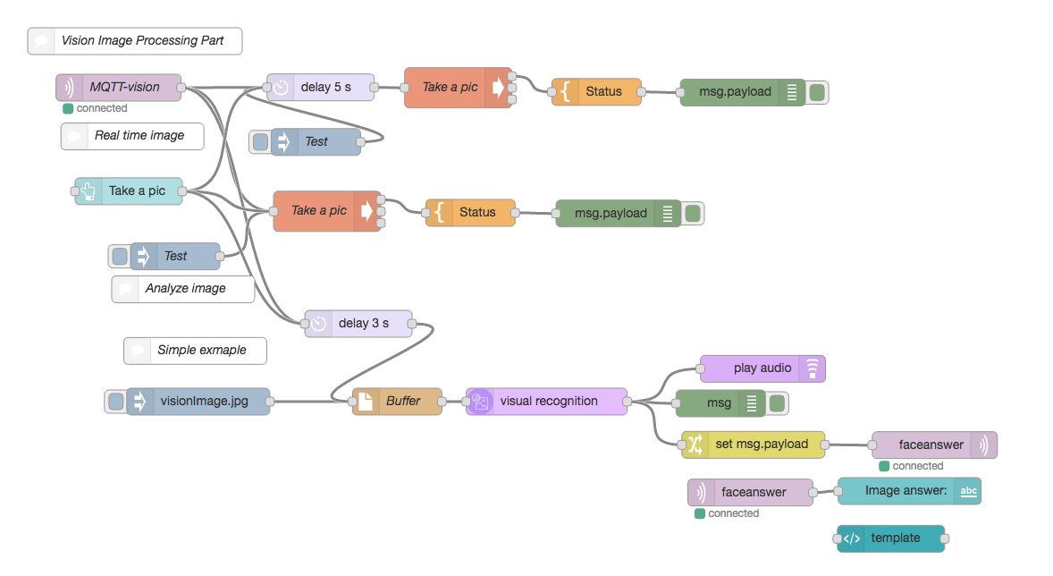
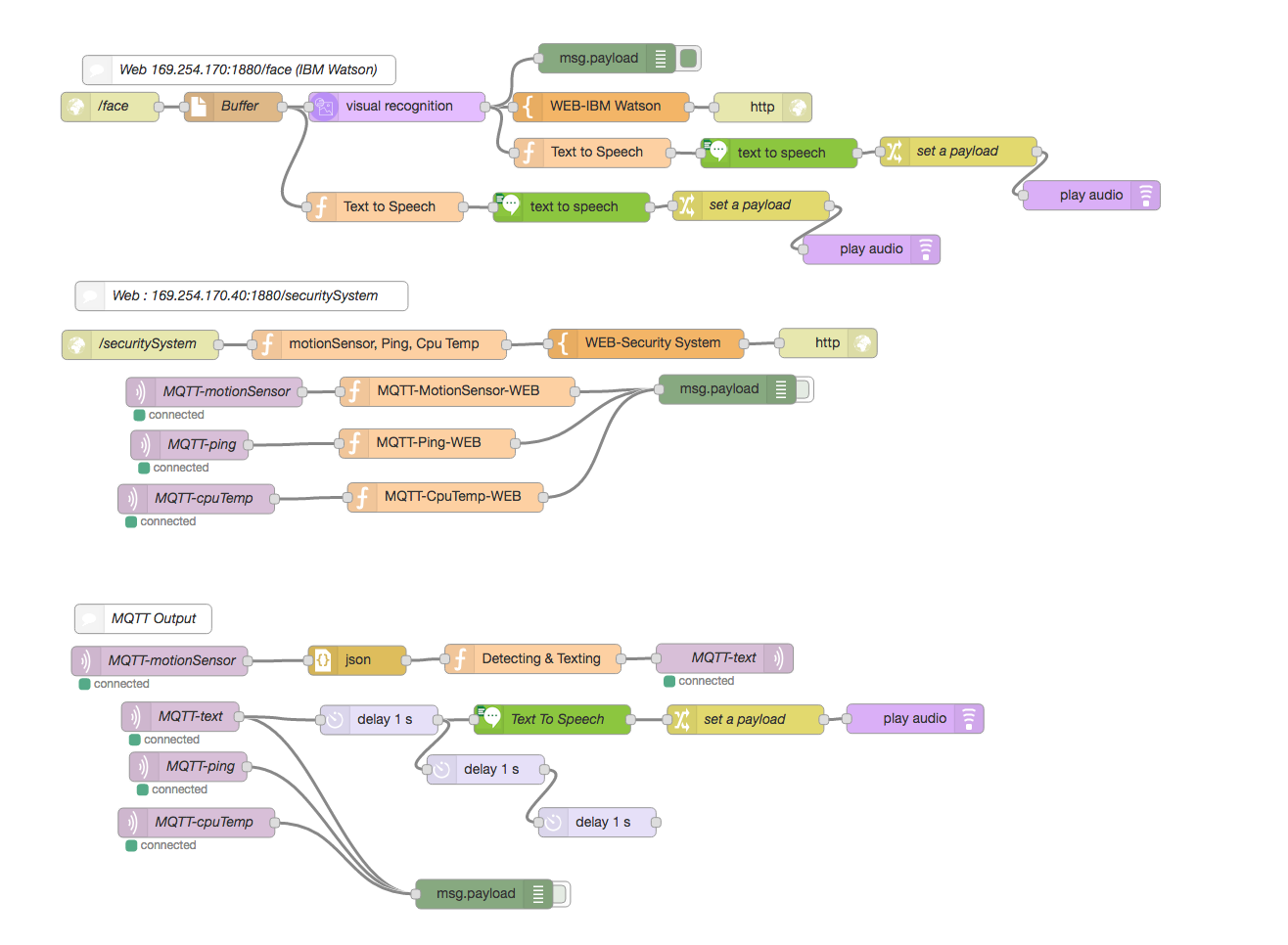
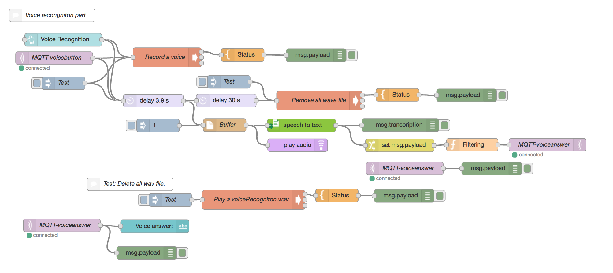
How to start Node-RED on web-browser.
(1) Write down command shown below to a terminal window.
node-red-start
(2) You can find an IP address as below. 'Once Node-RED has started, point a browser at http://169.254.170.40:1880' (It depends on your IP address)
(3) Open your web browser.
(4) Copy the IP address and paste on web-browser.
(5) It will display a visual editor of Node-RED on web-browser.
(6) You can start coding with visual editor on web-browser.
(7) Try dragging & dropping any node from the left-hand side to right-hand side. It's really easy to code. ( You can conveniently use the visual editor offline as well as online. ) Download all files at Download list. (1) Click the number (1) at the right-hand side corner shown in NodeRED on web-browser. (2) Click the Import button on the drop down menu. (3) Open the Clipboard shown in the above 1st picture. (4) Lastly, paste the given JSON format text of '____ver0.1.txt' (Download List) in Import nodes editor.
Setting Up MQTT V3.1 on Raspberry Pi2
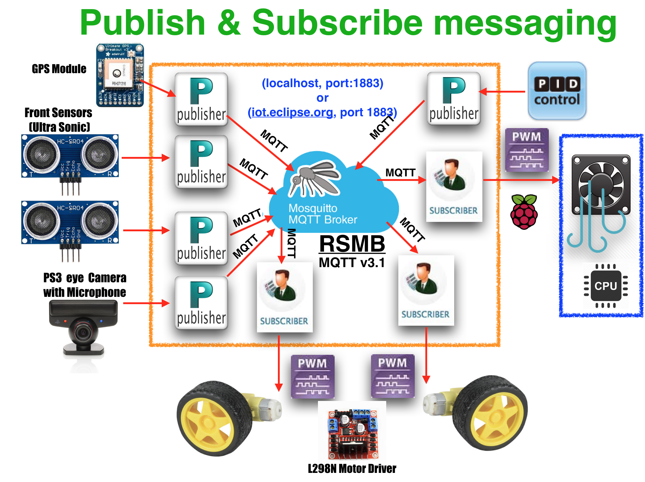
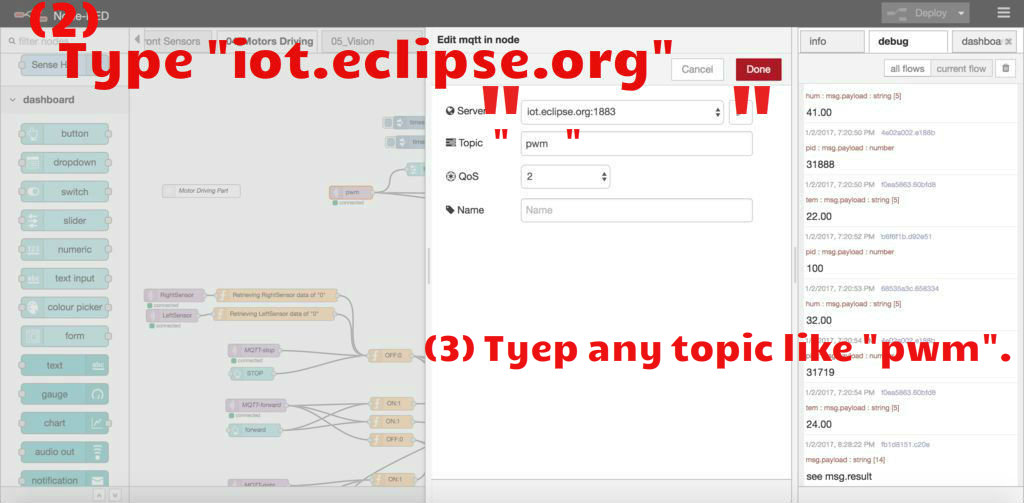
There are two options such as using eclipse paho, installing a mosquitto sever. Also, you can use (1) option instead of (2) opption.
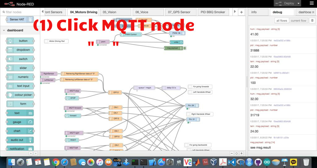
(1) Using "iot.eclipse.org".
Click each MQTT node and Type it.
iot.eclipse.org
(2) Setting up MQTT v3.1 on Raspberry Pi2
This message broker(Mosquitto) is supported by MQTT v3.1 and it is easily installed on the Raspberry Pi and somewhat less easy to configure. Next we step through installing and configuring the Mosquitto broker. We are going to install & test the MQTT “mosquitto” on terminal window. Click that.
https://www.instructables.com/id/PID-Control-for-CPU-Temperature-of-Raspberry-Pi/
Checking Your NodeRED Codes With MQTT on Raspberry Pi2
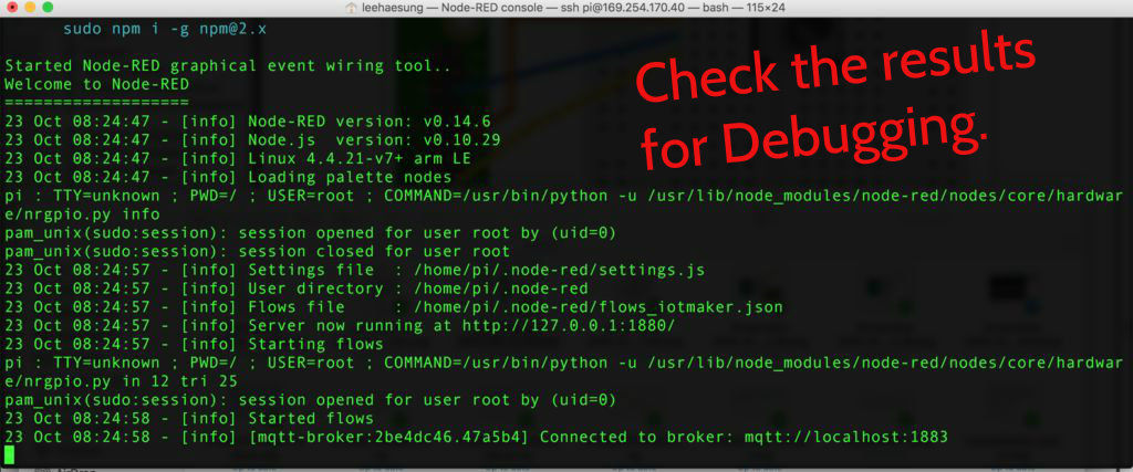
When you will use the JSON format of the 'NodeRED_Text_files_ver0.1.txt' (Download List) on Node-RED, it's automatically set up & coded each data. I have already set up the each data in each node.
(1) Click each node.
(2) Check information inside each node has been prefilled.
(3) Please don't change the set data. (The above can be customized for more advanced users.)
Adding & Setting Up PID Node, Dashboard on Raspberry Pi2
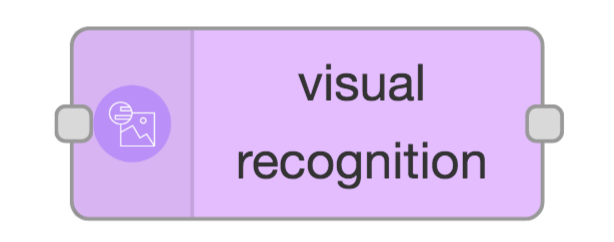

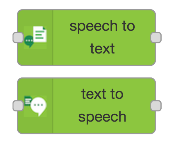



Searching the Nodes
Node-RED comes with a core set of useful nodes, but there are a growing number of additional nodes available for installing from both the Node-RED project as well as the wider community. You can search for available nodes in the Node-RED library or on the npm repository .
- For example, we are going to search 'node-red-node-pidcontrol' at the npm web. Click here .
- Then, we are going to install npm package, node-red-node-pidcontrol, node-red-dashboard on Raspberry Pi.
To add additional nodes you must first install the npm tool, as it is not included in the default installation. The following commands install npm and then upgrade it to the latest 2.x version.
sudo apt-get update
sudo apt-get install npm
sudo npm install -g npm@2.x
hash -r
cd /home/pi/.node-red
- For example, 'npm install node-red-{example node name}'
- Copy the 'npm install node-red-node-pidcontrol' from the npm web. Paste it on a terminal window.
- Ex: node-red-node-watson, node-red-contrib-play-audio, node-red-dashboard, node-red-node-pidcontrol
npm install node-red-node-watson node-red-contrib-play-audio node-red-node-pidcontrol node-red-dashboard
You will need to restart Node-RED for it to pick-up the new nodes.
node-red-stop
node-red-start
Close your web browser and reopen the web browser.
Configuring the PS3 EYE Camera With Microphone

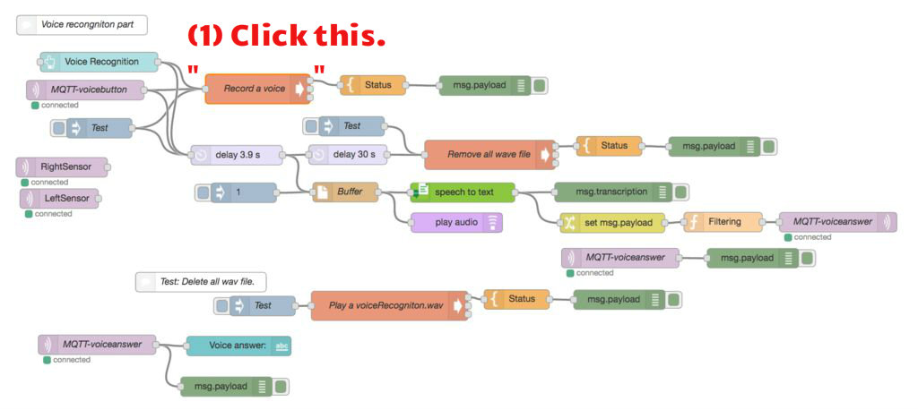
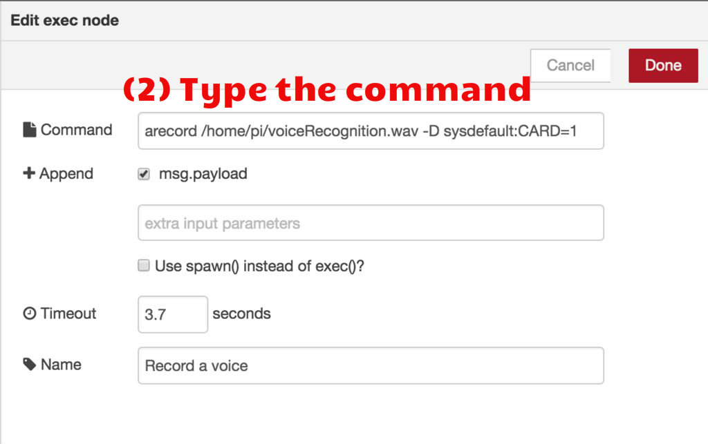
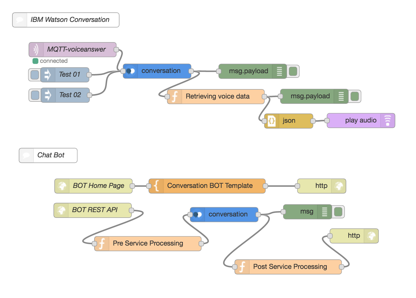
This Sony PS3 eye USB camera that can achieve up to 187 frames per second can be found for under $8 on Amazon.com that should make it quite a bargain for those wishing to experiment with CV projects. The PlayStation Eye camera for the PS3 is similar to a web camera but can also be used for computer vision and gesture recognition tasks. The PlayStation Eye has been supported by the Linux kernel since the late Linux 2.6 days but with a future update (Linux 3.20 or later given that the 3.19 merge window is closed) will support higher modes.
(1) Install a USB driver on Raspberry Pi.
sudo apt-get install fswebcam
(2) Take a picture and then check the 'visionImage.jpg' file in the /home/pi
(3) Don't forget to put the Bluemix service credentials for Watson Services such as Visual recognition, Speech to Text, and, Text to Speech. ( How to use the IBM Bluemix platform: https://console.ng.bluemix.net/docs/ )
(4) Make an image file (jpg) server for every boot.
cd /etc/xdg/autostart/
sudo nano imageFileServer.desktop
Type the description below or put the ‘imageFileServer.desktop’ file into /etc/xdg/autostart/ folder.
[Desktop Entry]
Type=Application
Name=imageFileServer
Comment=Start an image file server
NoDisplay=false
Exec=cd /home/pi
Exec=python -m SimpleHTTPServer 7000
Check the visionImage.jpg on the web browser.
Configuring GPS Sensor
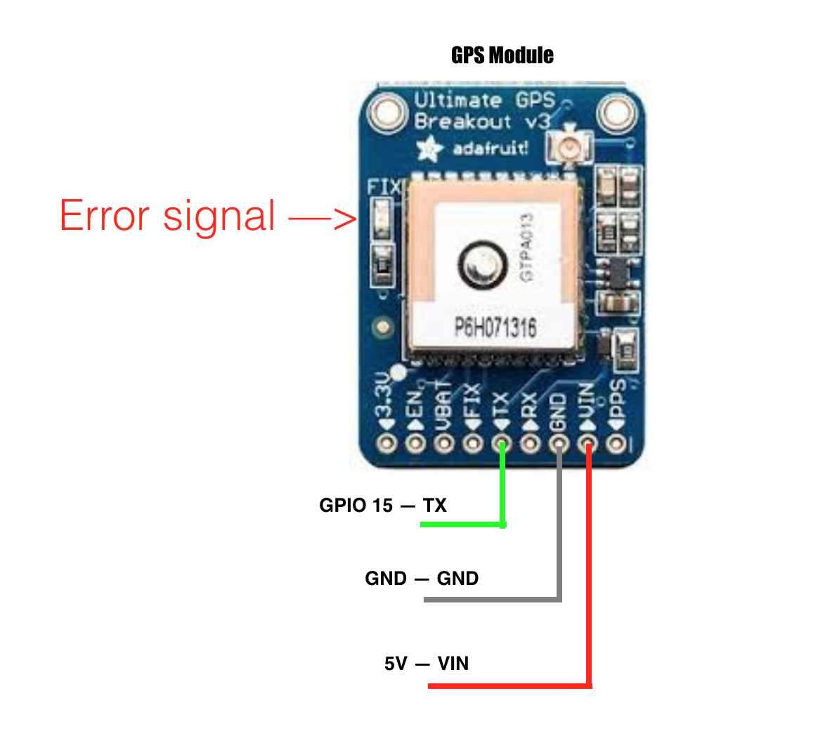
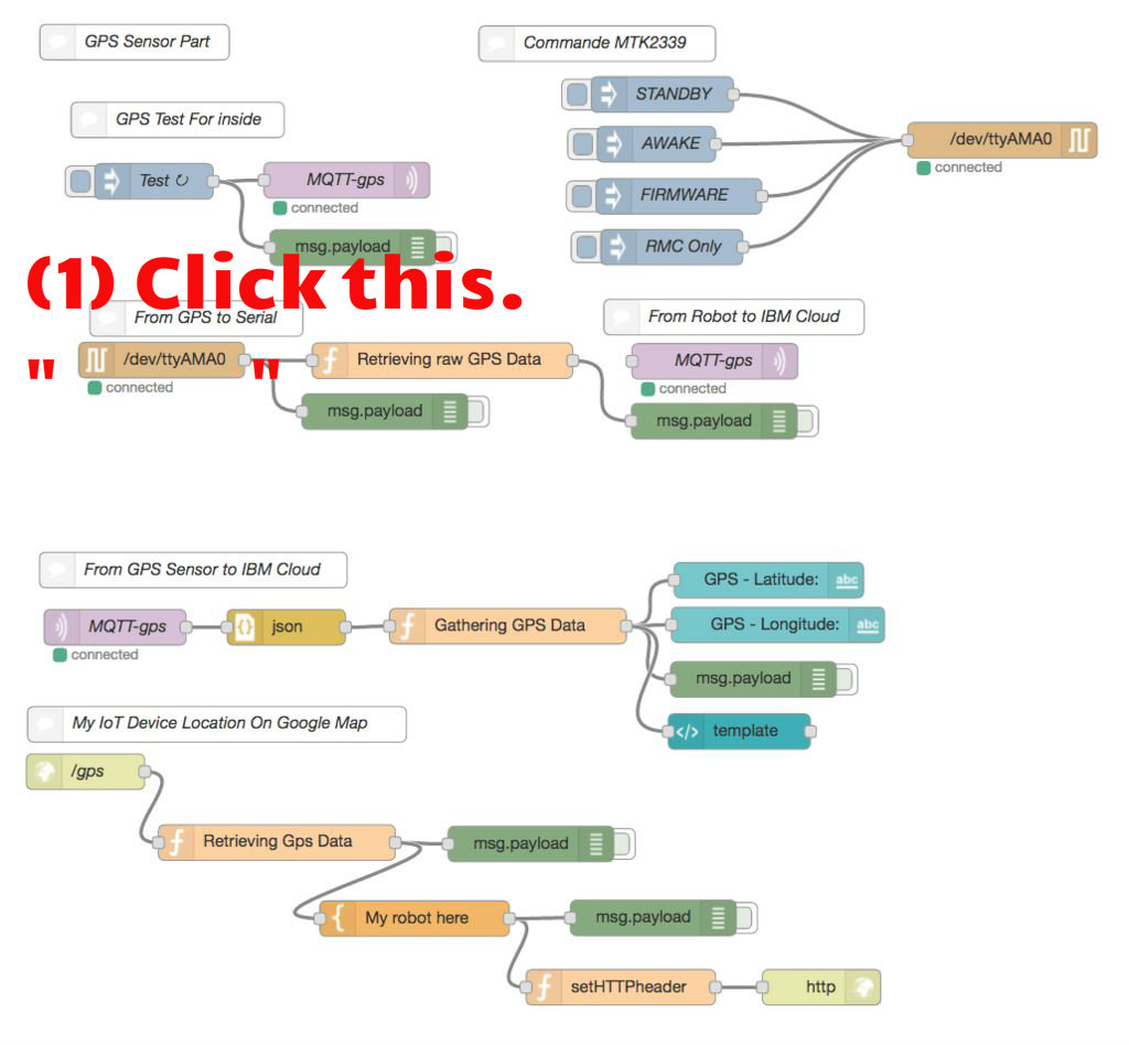
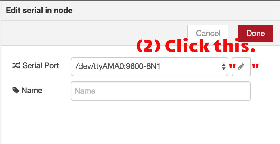
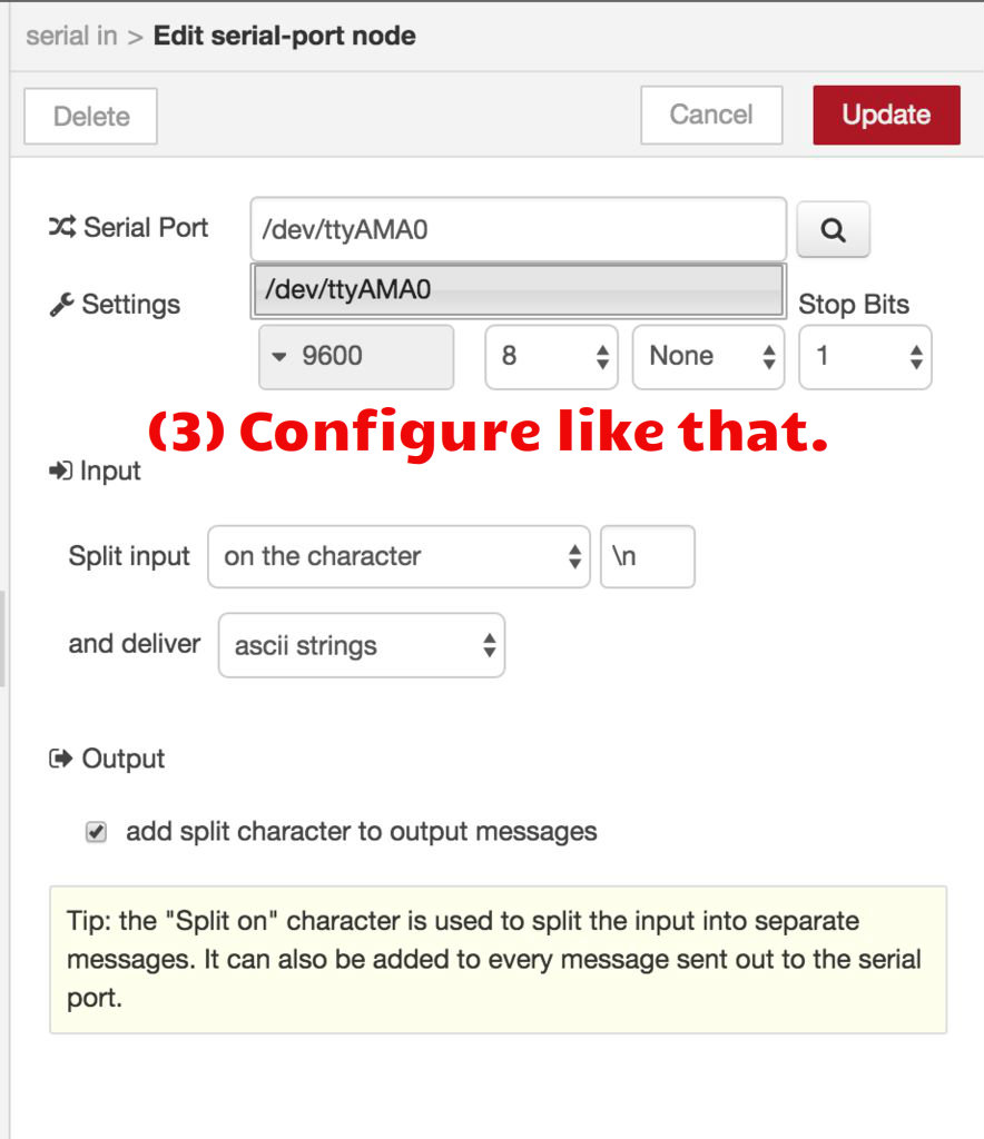
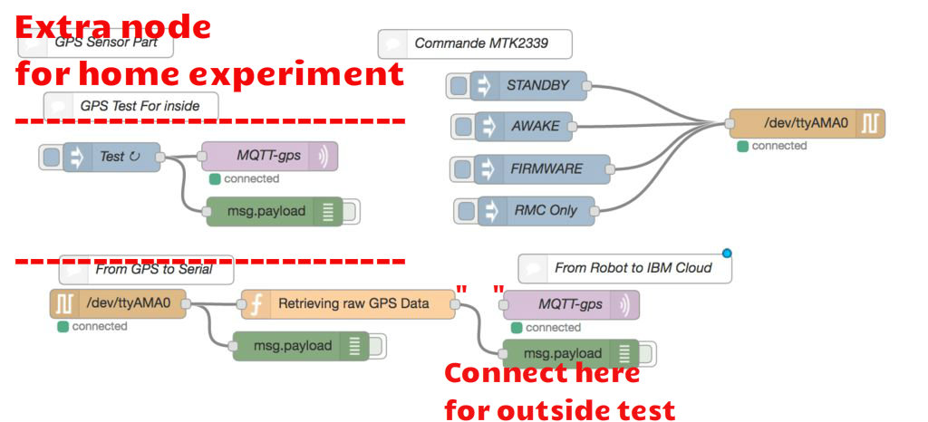
How to set the serial configuration for GPS module.
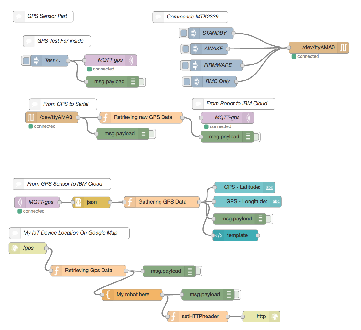
https://learn.adafruit.com/adafruit-ultimate-gps-on-the-raspberry-pi/using-uart-instead-of-usb
- Reference:
Adafruit Ultimate GPS & Download PDF file.
Tip: You should experiment the GPS sensor outside because this does not work inside at home. You would see an error signal. So, I made an extra node for home GPS test.
(1) Edit /boot/cmdline.txt
Next, enter the following command from the command line:
sudo nano /boot/cmdline.txt
And change:
dwc_otg.lpm_enable=0 console=ttyAMA0,115200 kgdboc=ttyAMA0,115200 console=tty1 root=/dev/mmcblk0p2 rootfstype=ext4 elevator=deadline rootwait
to:
dwc_otg.lpm_enable=0 console=tty1 root=/dev/mmcblk0p2 rootfstype=ext4 elevator=deadline rootwait
(eg, remove console=ttyAMA0,115200 and if there, kgdboc=ttyAMA0,115200)
Note you might see console=serial0,115200 or console=ttyS0,115200 and should remove those parts of the line if present.
(2) Edit /etc/inittab
(Raspbian Wheezy only)
From the command prompt enter the following command:
sudo nano /etc/inittab
And change:
#Spawn a getty on Raspberry Pi serial line

T0:23:respawn:/sbin/getty -L ttyAMA0 115200 vt100
to:
#Spawn a getty on Raspberry Pi serial line

#T0:23:respawn:/sbin/getty -L ttyAMA0 115200 vt100
That is, add a # to the beginning of the line!
(3) Only Raspbian Jessie
For the Raspberry Pi 1 or 2 (but NOT the 3!) Run the following two commands to stop and disable the tty service:
sudo systemctl stop serial-getty@ttyAMA0.service

sudo systemctl disable serial-getty@ttyAMA0.service
However for the Raspberry Pi 3 you need to use the /dev/ttyS0 port since that is what is normally connected to the GPIO serial port pins. Use these two commands instead:
sudo systemctl stop serial-getty@ttyS0.service

sudo systemctl disable serial-getty@ttyS0.service
(4) Raspberry Pi 3 Only
For the Raspberry Pi 3
You need to explicitly enable the serial port on the GPIO pins. The reason for this is a change with the Pi 3 to use the hardware serial port for Bluetooth and instead use a slightly different software serial port for the GPIO pins. A side effect of this change is that the serial port will actually change speed as the Pi CPU clock throttles up and down--this will unfortunately cause problems for most serial devices like GPS receivers!
Luckily there's an easy fix detailed in this excellet blog post to force the Pi CPU into a fixed frequency which prevents speed changes on the serial port. The Pi might not perform as well but it will have a stable serial port speed.
To make this change edit the /boot/config.txt file by running:
sudo nano /boot/config.txt
At the very bottom of the file add this on a new line:
enable_uart=1
ave the file (press Ctrl-O, then enter) and exit (press Ctrl-X). You're all set!
(5) Reboot your Pi
sudo reboot
(6) Restart GPSD with HW UART
Restart gpsd and redirect it to use HW UART instead of the USB port we pointed it to earlier. Simply entering the following two commands.
For the Raspberry Pi 1 or 2 (but NOT the 3!) run these commands:
sudo killall gpsd
sudo gpsd /dev/ttyAMA0 -F /var/run/gpsd.sock
And for the Raspberry Pi 3 run these commands to use the different serial port:
sudo killall gpsd
sudo gpsd /dev/ttyS0 -F /var/run/gpsd.sock
As with the USB example, you can test the output with:
cgps -s
Using a Dashboard for the Robot
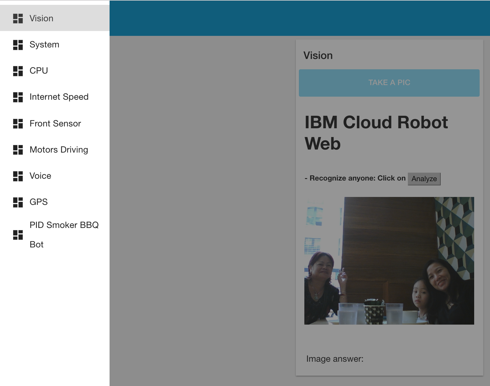
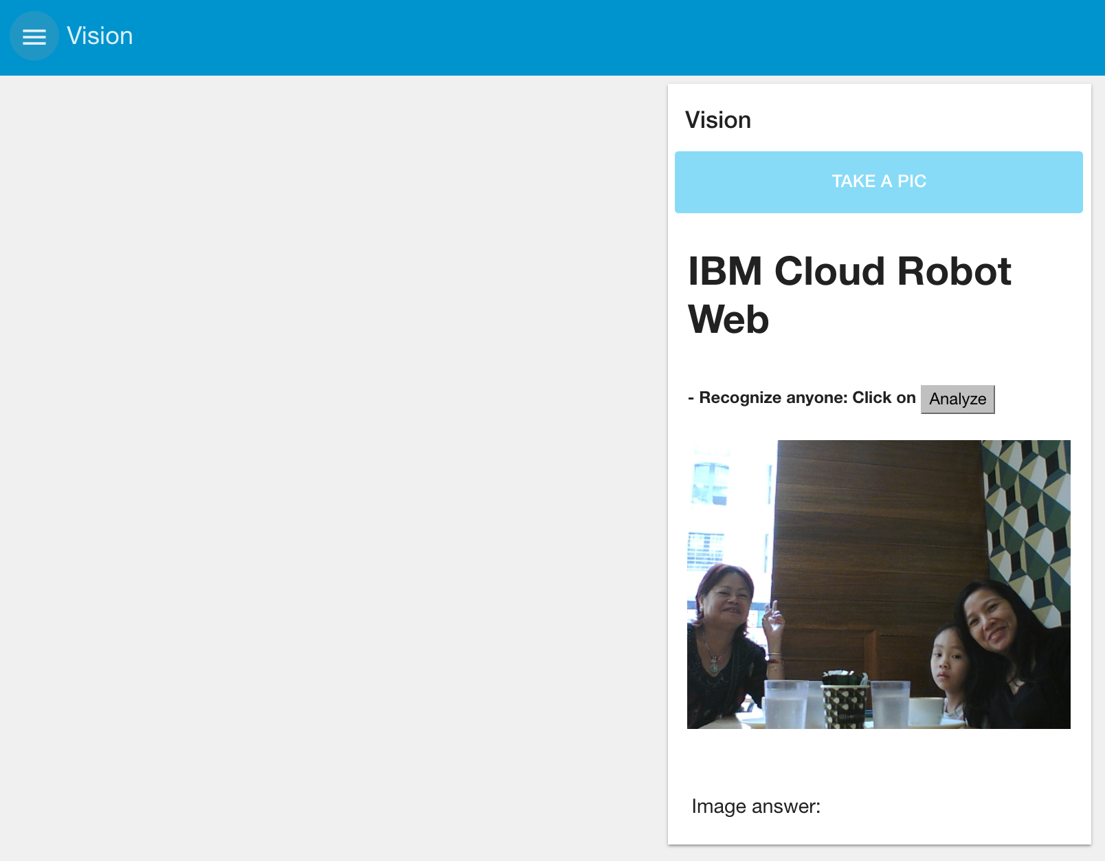
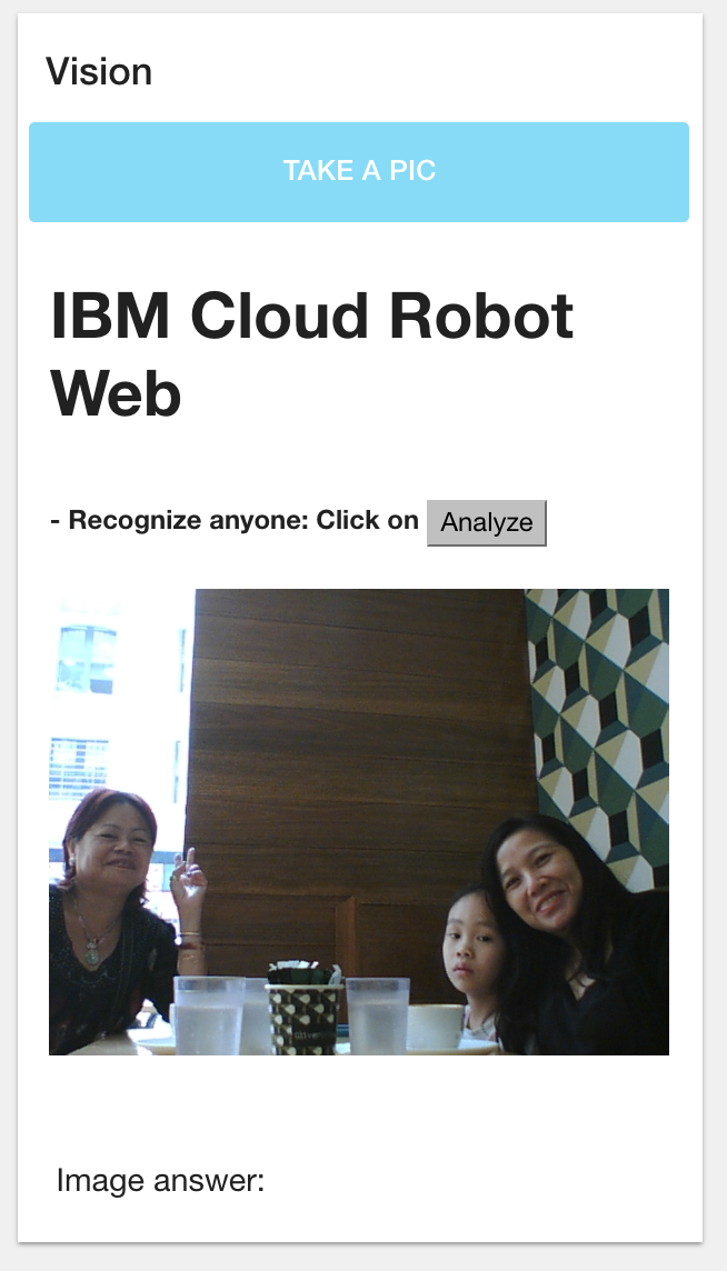
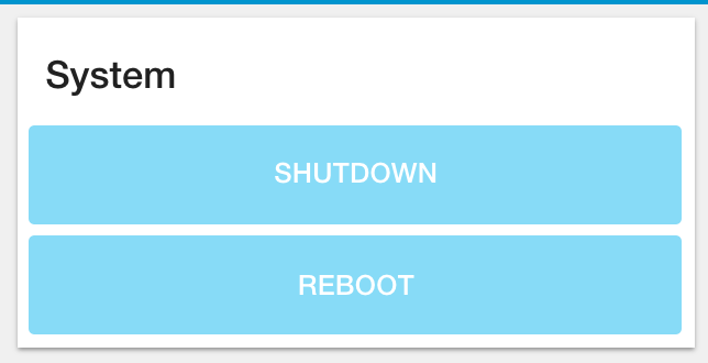
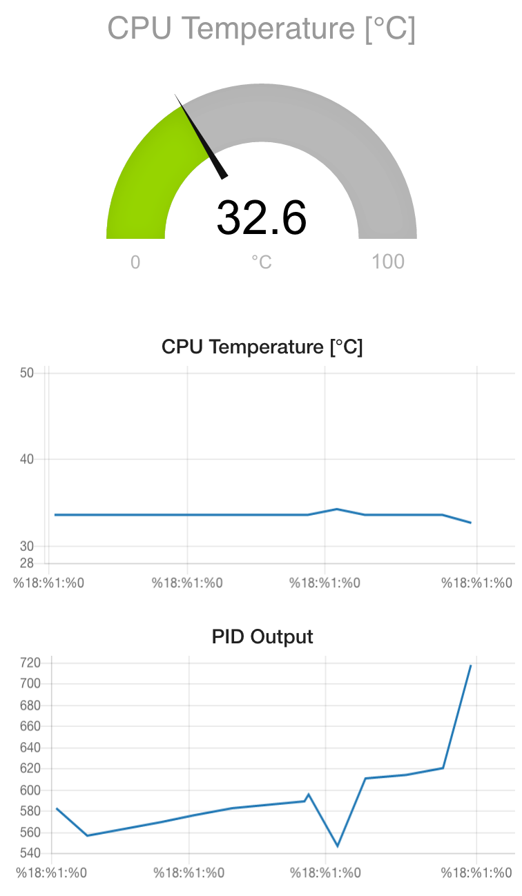
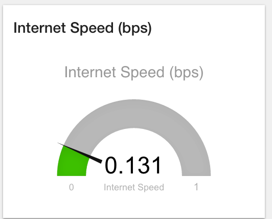
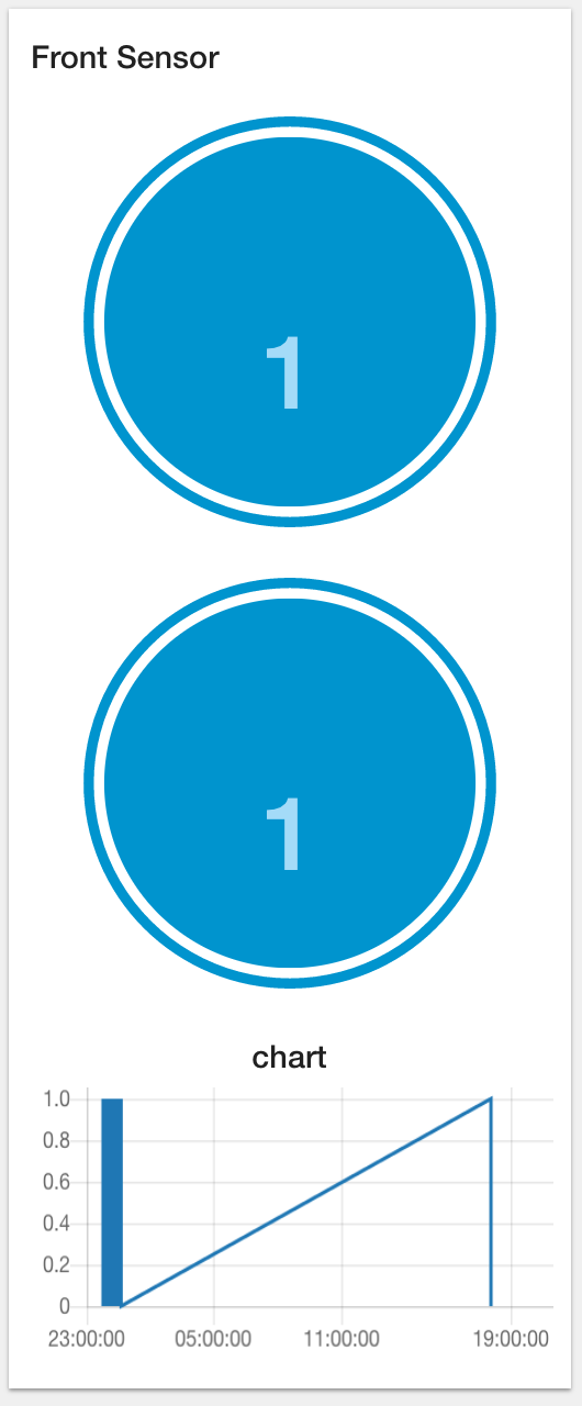
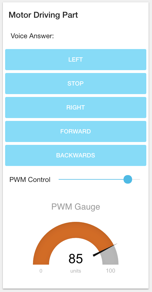
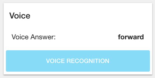
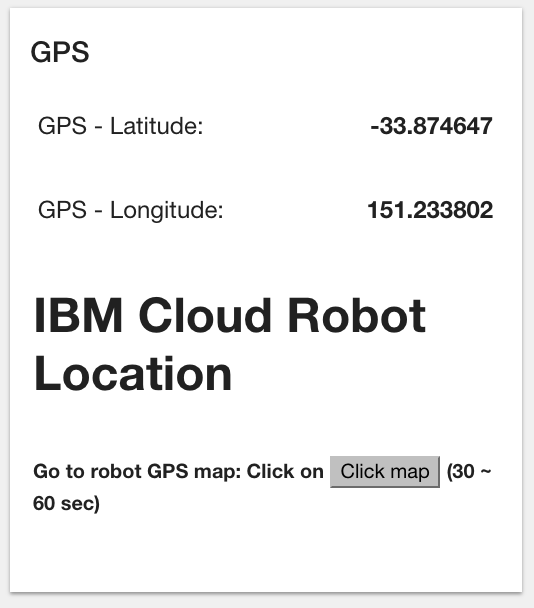
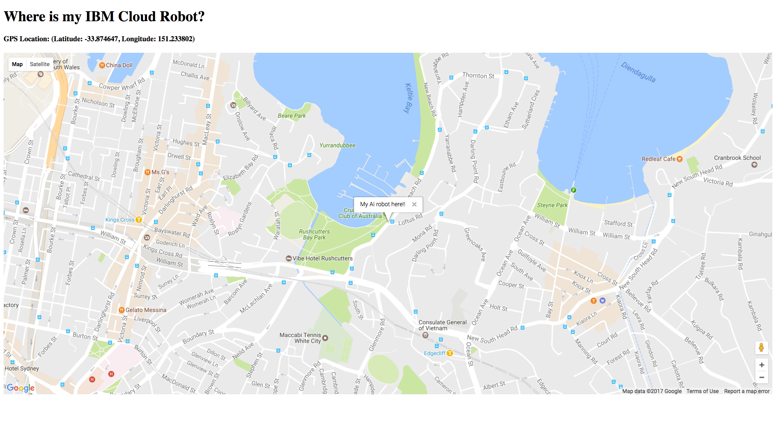
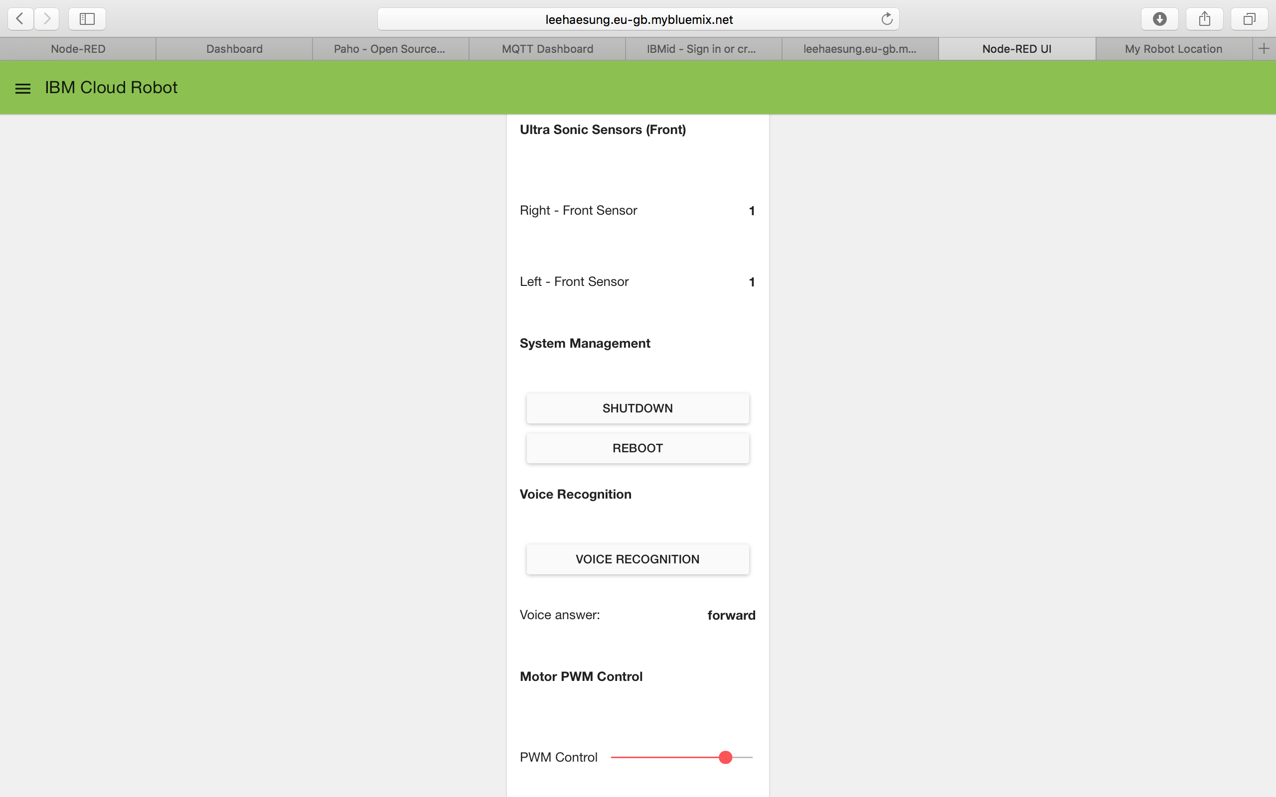
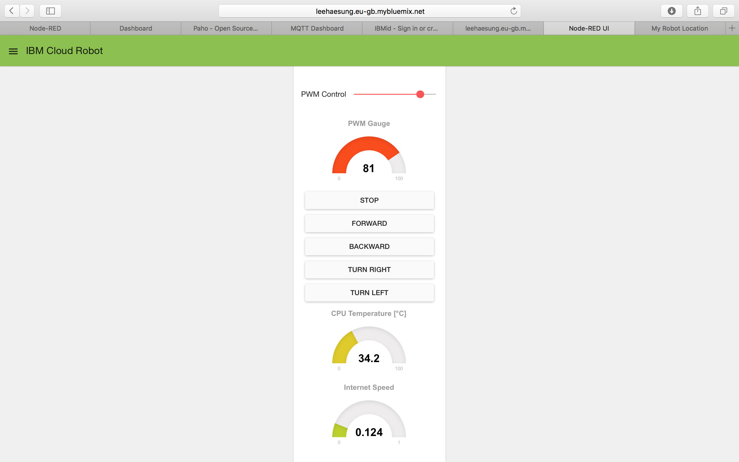
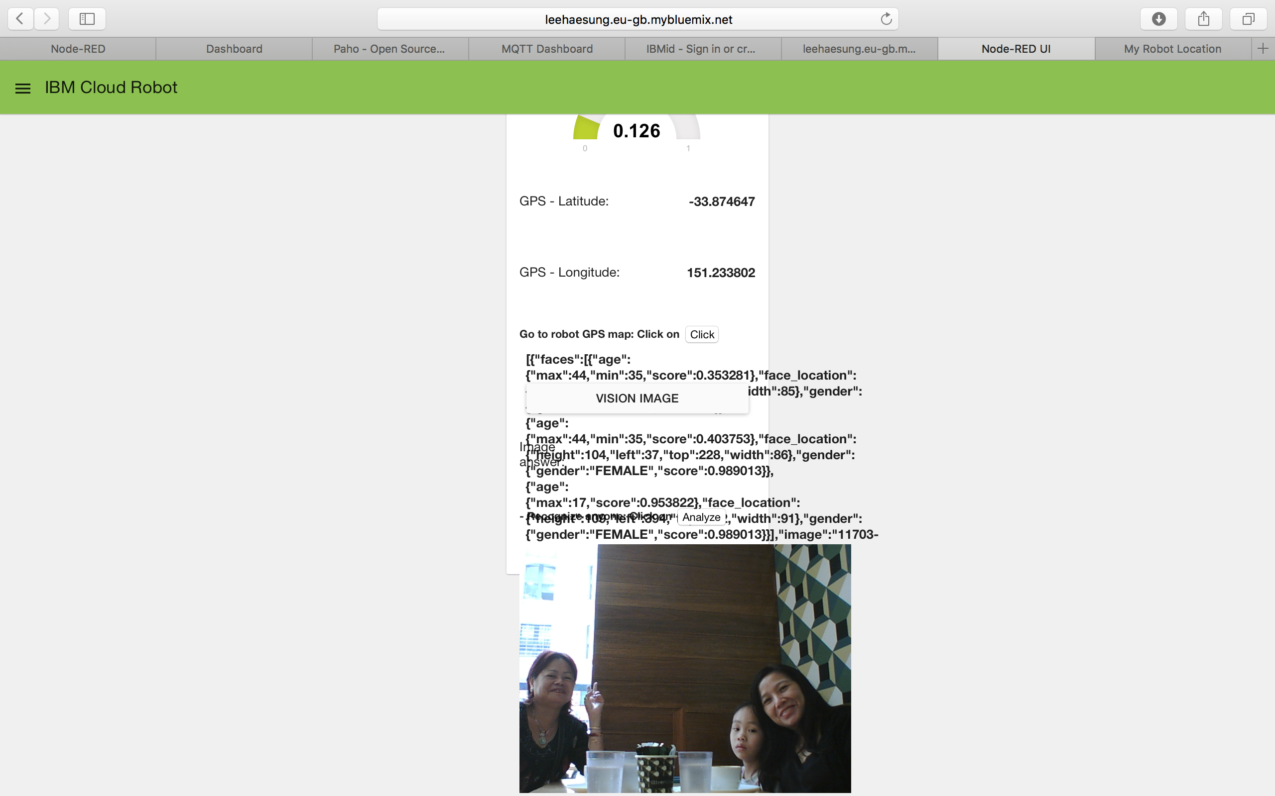
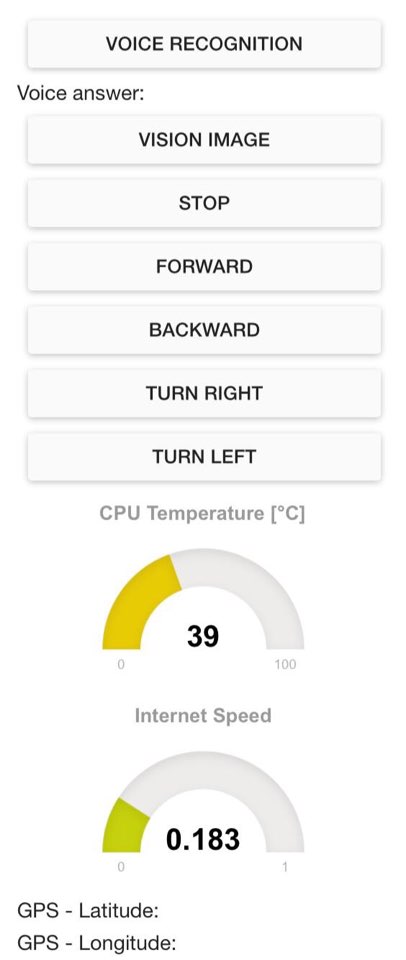
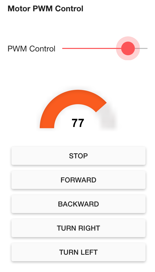
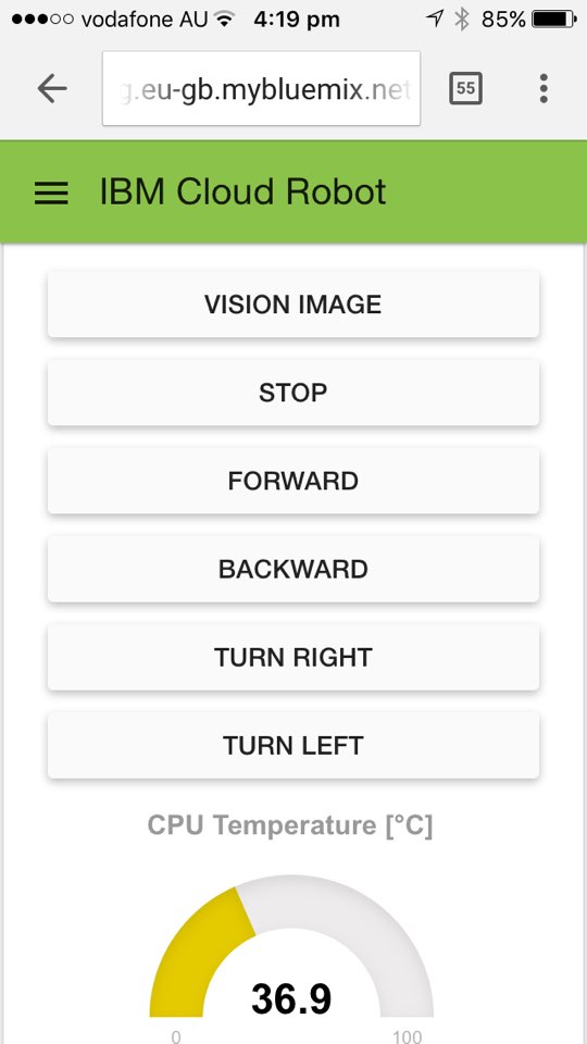
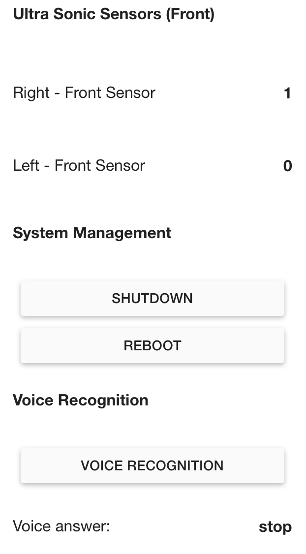
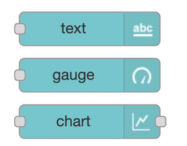
The dashboard is a visual UI tool like gauge, chart. There is a basic tutorial of a Node-RED dashboard using 'node-red-dashboard'
http://developers.sensetecnic.com/article/a-node-red-dashboard-using-node-red-contrib-ui/
Tuning PID Controller
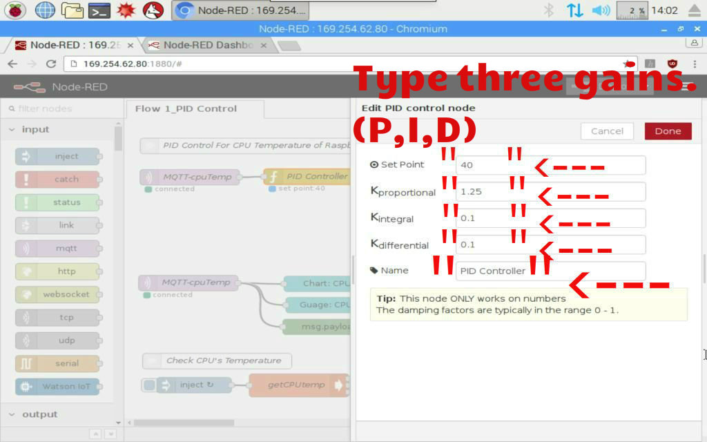
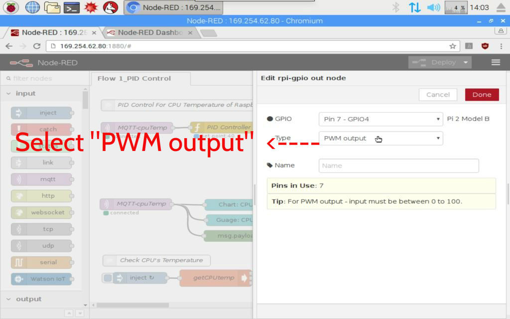
https://www.instructables.com/id/PID-Control-for-CPU-Temperature-of-Raspberry-Pi/
My instructable is really helpful to tune the PID gains for your system.
This is big job to adjust the pid gains. Use my source(node red) from the Download List.
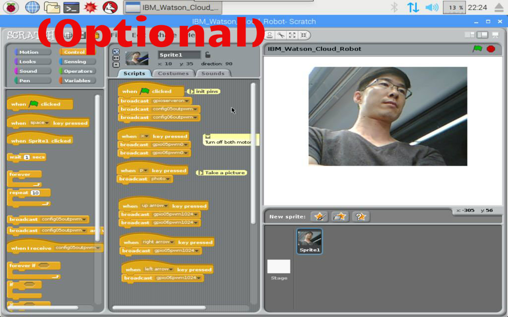
(Optional) Programing a Pi-Scratch Robot
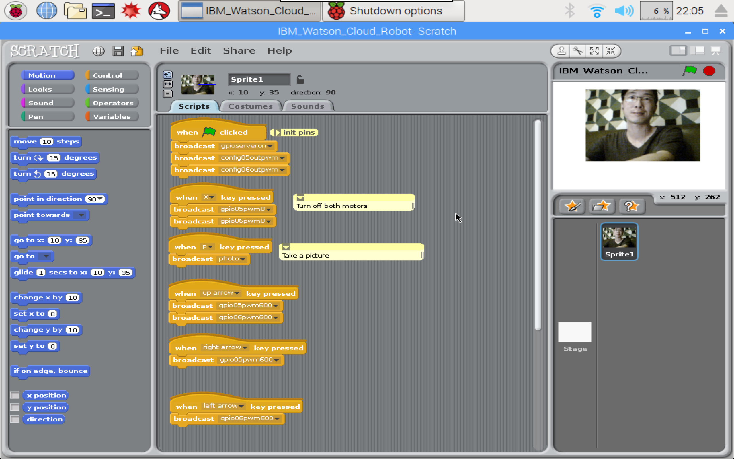


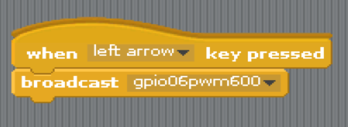
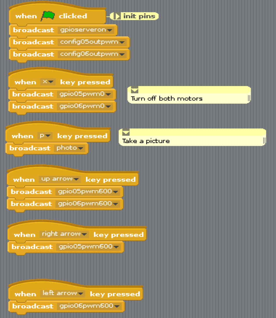
This part is an optional part for kid educational purpose. So, I developed it for my students in Sydney.
Let's have fun with kids!!
Download List
Please comment when you find some errors (bugs). I will fix the bug with version up.
Downloads
List of References
- MQTT.org: Version 3.1.1 becomes an OASIS Standard
- MQTT.org: Documentation
- Eclipse Paho
- What is Really Small Message Broker(RSMB)? (IBM)
- Node-RED.org: Documentation
- Node-RED: Running on Raspberry Pi
- Node-RED: Writing Functions
- JavaScript Reserved Words
- Node-RED: Node-RED Library
- RUN KIT: PID controller
- GitHub: A node advanced PID controller based on the Arduino PID library (index.js By wilberforce)
- GitHub: Node.js PID controller By wilberforce
- GitHub: node-red-nodes/function/PID/pidcontrol.js By dceejay
- Excel PID simulator
- PID Tutorial
- Automating my fan based off of the CPU temperaturePID Controller Wikipedia
- Automatically tune PID controller gains
- PID Controller Tuning in Simulink
- Modern Control Engineering Fifth Edition Katsuhiko Ogata
- Automatic Control Systems 9th Edition BENJAMIN C. KUO
- Modern Control Systems 12th Edtion Richard C. Dorf
Version Note
--------------------------------------------------------------------------
Version rules
- VerX.Y
- X: Changed
- Y: Added
- (Ex 01) file__Ver0.2 : added something
- (Ex 02) file__Ver1.0 : changed something
--------------------------------------------------------------------------
- 02_CPU_SQLite_Part_Ver0.2.txt : added SQLite For CPU Temperature (9 Dec 2017)
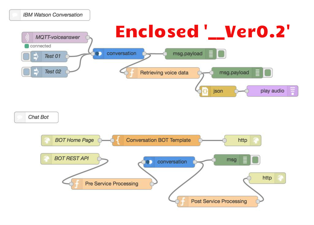
- 06_Voice_Part_Ver0.2.txt : added a Watson Conversation (17 Jan 2017)