I2C Between Arduinos

Maybe sometimes we want to share the workload of one Arduino with another. Or maybe we want more digital or analog pins. Inter-Integrated Circuit or I2C (pronounced I squared C) is the best solution.
I2C is an interesting protocol. It's usually used to communicate between components on motherboards in cameras and in any embedded electronic system.
Here, we will make an I2C bus using two Arduinos. We will program one master Arduino to command the other slave Arduino to blink its built-in LED once or twice depending on the received value.
In order to build this we need the following "ingredients":
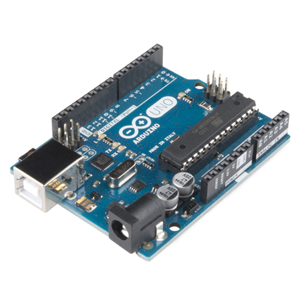
- 2 Arduinos
- Jumper cables
This instructable and many more can be found in my Arduino Development Cookbook available here. :D
How to Connect Them


Follow these steps to connect two Arduino UNOs using I2C:
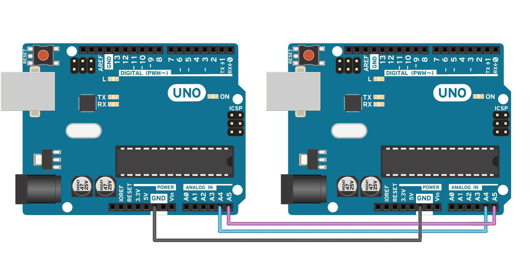
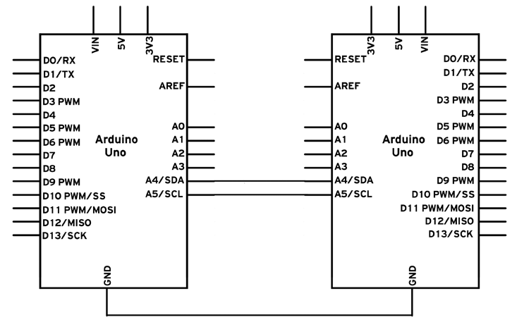
- Connect pins A4 and A5 on one Arduino to the same pins on the other one.
-
The GND line has to be common for both Arduinos. Connect it with a jumper.
We also have a schematic and a "breadboard" implementation, both easy to follow. Luckily, it's a simple implementation.
Remember never to connect 5 V and 3.3 V Arduinos together. It won't
hurt the 5V Arduino, but it will certainly annoy its 3.3 V brother!
Code
The following code is split in two parts: the master code and the slave code, which run on two different Arduinos. First, let's take a look at the master code:
// Include the required Wire library for I2C<br>#include
int x = 0;
void setup() {
  // Start the I2C Bus as Master
  Wire.begin();
}
void loop() {
  Wire.beginTransmission(9); // transmit to device #9
  Wire.write(x);              // sends x
  Wire.endTransmission();    // stop transmitting
  x++; // Increment x
  if (x > 5) x = 0; // `reset x once it gets 6
  delay(500);
}
And here is the slave code that interprets the characters sent from the master:
// Include the required Wire library for I2C<br>#include <Wire.h>
int LED = 13;
int x = 0;
void setup() {
  // Define the LED pin as Output
  pinMode (LED, OUTPUT);
  // Start the I2C Bus as Slave on address 9
  Wire.begin(9);
  // Attach a function to trigger when something is received.
  Wire.onReceive(receiveEvent);
}
void receiveEvent(int bytes) {
  x = Wire.read();    // read one character from the I2C
}
void loop() {
  //If value received is 0 blink LED for 200 ms
  if (x == '0') {
    digitalWrite(LED, HIGH);
    delay(200);
    digitalWrite(LED, LOW);
    delay(200);
  }
  //If value received is 3 blink LED for 400 ms
  if (x == '3') {
    digitalWrite(LED, HIGH);
    delay(400);
    digitalWrite(LED, LOW);
    delay(400);
  }
}Code Breakdown
First, let's look at the master. We need to include the required Wire.h library:
#include <Wire.h>
Then, in the setup function, we begin the I2C bus using the Wire.begin() function. If no argument is provided in the function, Arduino will start as a master.
Lastly, we send a character x, which is between 0 and 5. We use the following functions to
begin a transmission to the device with the address 9, write the character, and then stop the transmission:
Wire.beginTransmission(9); // transmit to device #9
Wire.write(x);             // sends x
Wire.endTransmission();    // stop transmitting
Now let's explore the slave Arduino code. We also include the Wire.h library here, but now we start the I2C bus using Wire.begin(9). The number in the argument is the address we want to use for the Arduino. All devices with address 9 will receive the transmission.
Now we need to react somehow when we receive an I2C transmission. The following function appends a trigger function whenever a character is received. Better said, whenever the Arduino receives a character on I2C, it will run the function we tell it to run:
Wire.onReceive(receiveEvent);
And this is the function. Here, we simply store the value of the received character:
void receiveEvent(int bytes) {
   x = Wire.read();
}
In loop(), we simply interpret that character to blink the built-in LED at different speeds depending on the received character.
More About I2C
To briefly go through the theory, I2C requires two digital lines: Serial Data line (SDA) to transfer data and Serial Clock Line (SCL) to keep the clock. Each I2C connection can have one master and multiple slaves. A master can write to slaves and request the slaves to give data, but no slave can directly write to the master or to another slave. Every slave has a unique address on the bus, and the master needs to know the addresses of each slave it wants to access.
Each I2C bus can support up to 112 devices. All devices need to share GND. The speed is around 100 kb/s—not very fast but still respectable and quite usable. It is possible to have more than one master on a bus, but it's really complicated and generally avoided.
A lot of sensors use I2C to communicate, typically Inertial Measurement Units, barometers,
temperature sensors, and some Sonars. Remember that I2C is not designed for long cable lengths. Depending on the cable type used, 2 meters might already cause problems.
I2C is a complicated transmission protocol, but it's very useful. All Arduinos implement it, with a few differences in pin mappings:
Board I2C pins
Uno, Pro Mini A4 (SDA), A5 (SCL)
Mega, Due 20 (SDA), 21 (SCL)
Leonardo, Yun 2 (SDA), 3 (SCL)
Connecting More Devices

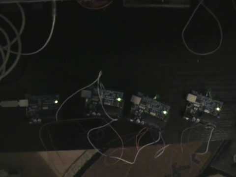
If we need to connect more than two devices on an I2C bus, we just have to connect all SDA and SCL lines together. We will need the address of every slave to be addressed from the master Arduino.
Here is a video of a personal implementation using 1 master and 3 slaves.
More topics regarding Arduino communications such as Wireless Serial, SD cards or Ethernet can be found in my Arduino Development Cookbook available here. :D