I2C Sensor Hub


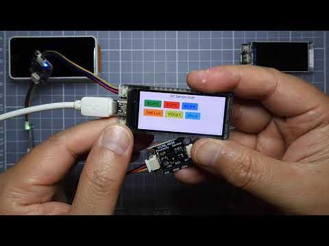
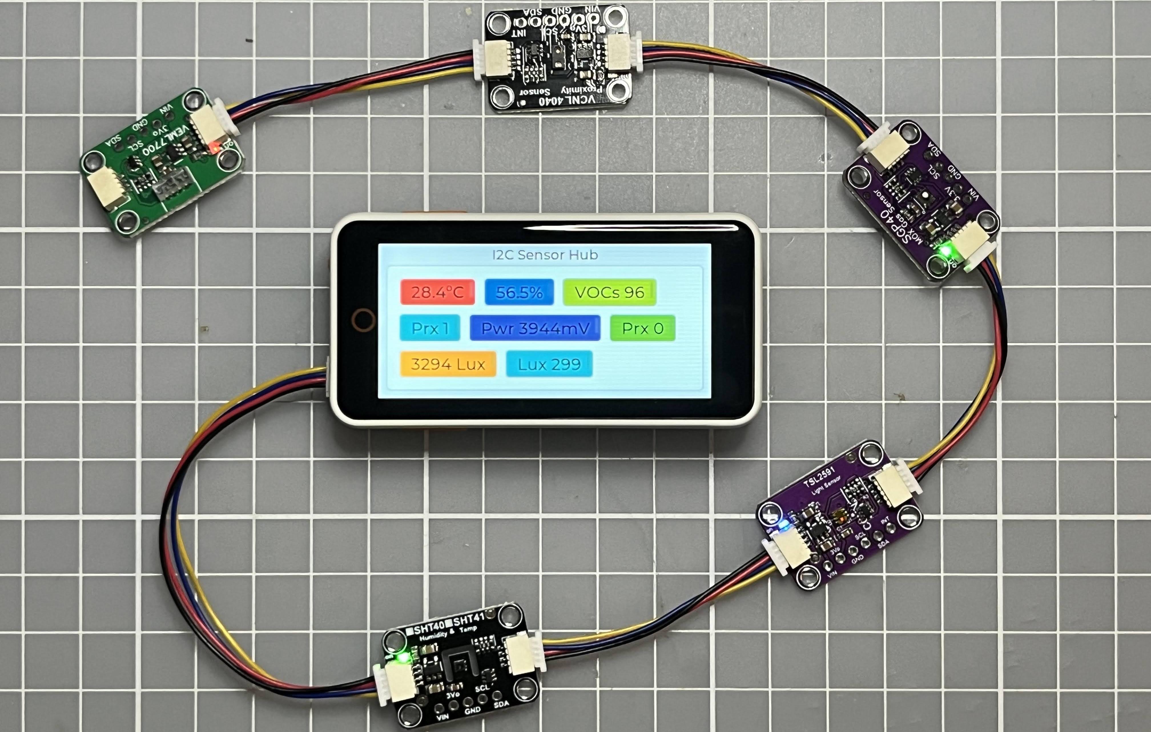
This instructables show how to use a dev board connect to various I2C sensors to build an I2C sensor hub.
Supplies

- Any dev device with display and STEMMA QT / Qwiic port should be ok
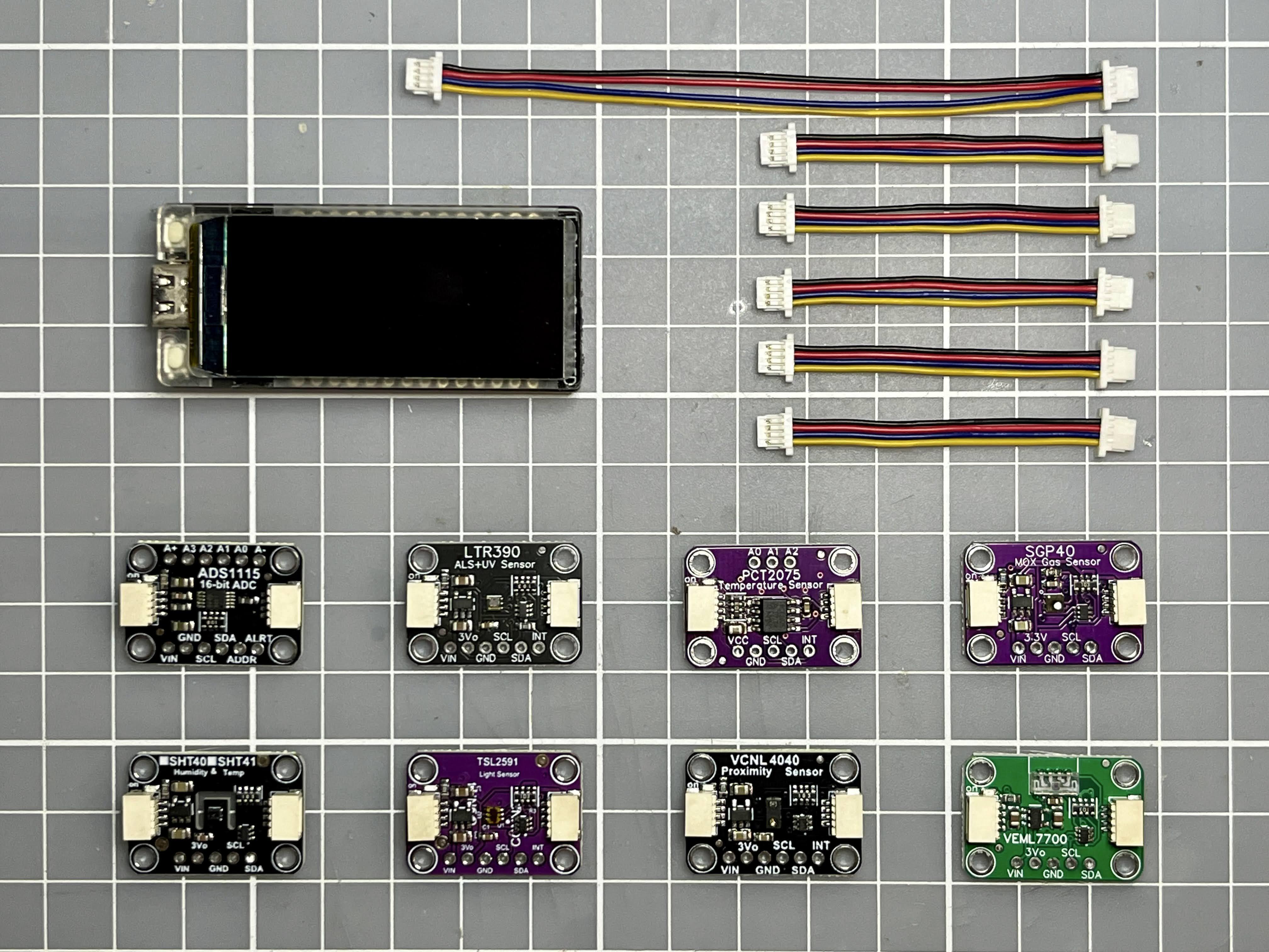
- Some STEMMA QT / Qwiic sensor modules
- STEMMA QT / Qwiic JST SH 4-Pin Cables
This project tested with below dev devices:
Note:
- This project use 2 GPIO physical buttons to build a simple UI. If your dev device did not have physical buttons, simply add a buttons module can do the job.
- I2C sensors have 2 types of connector, Grove/STEMMA and Qwiic/STEMMA QT. Most of them are compatible, you just need prepare some converting cables, e.g.
- https://www.sparkfun.com/products/15109
- https://www.aliexpress.com/item/3256804861770947.html
- https://www.adafruit.com/product/4528
What Is I2C?
I2C (Inter-Integrated Circuit; pronounced as “eye-squared-see” or “eye-two-see”), alternatively known as I2C or IIC, is a synchronous, multi-controller/multi-target (historically-termed as master/slave), single-ended, serial communication bus invented in 1982 by Philips Semiconductors. It is widely used for attaching lower-speed peripheral integrated circuits (ICs) to processors and microcontrollers in short-distance, intra-board communication.
I2C bus can be found in a wide range of electronics applications where simplicity and low manufacturing cost are more important than speed.
Since the data volume of most sensors are relatively low, so it is very suitable using I2C interface for a low cost solution.
Ref.:
What Is Qwiic?

Qwiic is a standardized, plug-and-play connectivity system developed by SparkFun Electronics. It uses a series of 4-pin JST SH connectors and cables to quickly and easily connect various sensors, displays, and other components using the I2C protocol without the need for soldering or wiring. Qwiic is solder free, daisy chain-able, and uses polarized connectors to prevent accidental pin swapping to be user-friendly and allow for fast prototyping and development of IoT projects.
Qwiic helps you fast prototyping. And this project, I2C Sensor Hub, helps you fast test the sensor metrics and behaviors of the modules before your development kickstart.
Besides SparkFun, Adafruit also introduced STEMMA QT modules that can compatible with Qwiic.
So, for smaller I2C devices, we'll use the JST SH that SparkFun Qwiic uses, so that Qwiic & STEMMA QT sensors are cross-compatible!
STEMMA QT devices keep the level shifting/regulator, so you can use STEMMA QT with Grove/Gravity/STEMMA/Qwiic controllers at any voltage range, safely!
Ref.:
https://www.sparkfun.com/qwiic
https://www.digikey.com/en/maker/platforms/q/qwiic
https://learn.adafruit.com/introducing-adafruit-stemma-qt/what-is-stemma-qt
Various I2C Sensors
The sensor modules with 2 Qwiic connectors are more handy to connect all in a series (actually the circuit should call connect in parallel), so I will support those modules first.
Current I have below sensor modules in hand and tested:
The ADS1115 are precision, low-power, 16-bit, I2C- compatible, analog-to-digital converters (ADCs).
The LTR390 is one of the few low-cost UV sensors available, and it's a pretty nice one! With both ambient light and UVA sensing with a peak spectral response between 300 and 350nm. You can use it for measuring how much sun you can get before needing to covering up.
PCF85063
The PCF85063 is a CMOS Real-Time Clock (RTC) and calendar optimized for low power consumption.
The PCT2075 is a temperature-to-digital converter featuring ±1 °C accuracy over -25 °C to +100 °C range.
The SGP40 is a digital gas sensor designed for easy integration into air purifiers or demand-controlled ventilation systems.
The SHT41 sensor is the fourth generation of I2C temperature and humidity sensor from Sensirion.
The TSL2591 luminosity sensor is an advanced digital light sensor, ideal for use in a wide range of light situations.
The VCNL4040 is a handy two-in-one sensor, with a proximity sensor that works from 0 to 200mm (about 7.5 inches) and light sensor with range of 0.0125 to 6553 lux.
The VEML7700 Ambient Light Sensor makes your life easier by calculating the lux, which is an SI unit for light.
There are much more sensors available. Given that the I2C sensor module have corresponding Arduino library, it can support by this I2C Sensor Hub.
Software Preparation
Arduino IDE
Download and install Arduino IDE latest 1.x version if not yet:
https://www.arduino.cc/en/software
Arduino-ESP32
Follow installation step to add Arduino-ESP32 support if not yet:
https://docs.espressif.com/projects/arduino-esp32/en/latest/installing.html
Arduino_GFX Library
Open Arduino IDE Library Manager by selecting "Tools" menu -> "Manager Libraries...". Search "GFX for various displays" and press "install" button.
You may refer my previous instructables for more information about Arduino_GFX.
LVGL
Open Arduino IDE Library Manager by selecting "Tools" menu -> "Manager Libraries...". Search "LVGL" and press "install" button.
Sensor Libraries


Please install all supported sensors libraries in Arduino IDE, the keywords for searching corresponding libraries are:
- ADS1x15
- LTR390
- PCT2075
- RTClib
- SensorLib
- SGP40
- SHT4x
- SY6970
- TSL2591
- VCNL4040
- VEML7700
Note:
You may refer to Arduino Documentation for the details on how to install/import library to Arduino IDE.
Main Design
The I2C Sensor Hub program try to read data for each I2C address. If the address have response, call the corresponding function to show the UI.
The UI is using LVGL, each newly detected sensor will add the metric label to the main screen. And then also create a new screen plot the graph of the sensor metrics in time sequence.
Source Code
Please download the source code at GitHub:
https://github.com/moononournation/I2C_Sensor_Hub
Open I2C_Sensor_Hub.ino in Arduino IDE. The program is tested with few dev devices, each dev device have their own pin configurations. It define separately in independant header files, you can uncomment corresponding header at around line 37:
Note:
You can also define your own pin configuration header file for your dev device, simply copy one of the header file as template and change the contents.
Upload Program
Connect your dev device and select corresponding board parameters, then simply press the Arduino IDE upload button to upload the program.
Implement New Sensor Support
If you would contribute for the new sensor support, simply copy one of sensor_*.h file as template then change the logic for your sensor. If you sensor have multiple metrics, you may start from sensor_ADS1x15.h; single metric sensor can start from sensor_LTR390.h.
Or if your sensor no need to plot graph, you may start from sensor_PCF85063.h. It actually a RTC and it is no much meaning to plot the timestamp, so it only show a label in main screen.
Lazy Initialization
Each sensor defines their own header file, all logic handle in one update function, e.g. update_ads1x15() for ADS1x15 sensor. The sensor_loop() function will call corresponding update function if found the sensor while each scanning.
The I2C Sensor Hub can support many sensors, but not all sensors connected at the beginning. So the sensor objects will not be created until the first update call, this is lazy initialization design.
I2C Mapping List
The update functions are registered at the func_list array in sensors_func.h header file. I2C have 127 possible addresses, so the array have 127 items. The array index represent the sensor address registered the corresponding update function and the address not yet registered set nullptr. E.g. VEML7700 Proximity Sensor default address is 0x10, so the array index 16 registered update_veml7700.
Happy Prototyping!

Now you can compare similar sensors metrics and behavior, then choose the suitable one for your project prototype.