I2C Communication Between Raspberry Pi Pico and NodeMCU
by pro-nav in Circuits > Microcontrollers
5332 Views, 3 Favorites, 0 Comments
I2C Communication Between Raspberry Pi Pico and NodeMCU
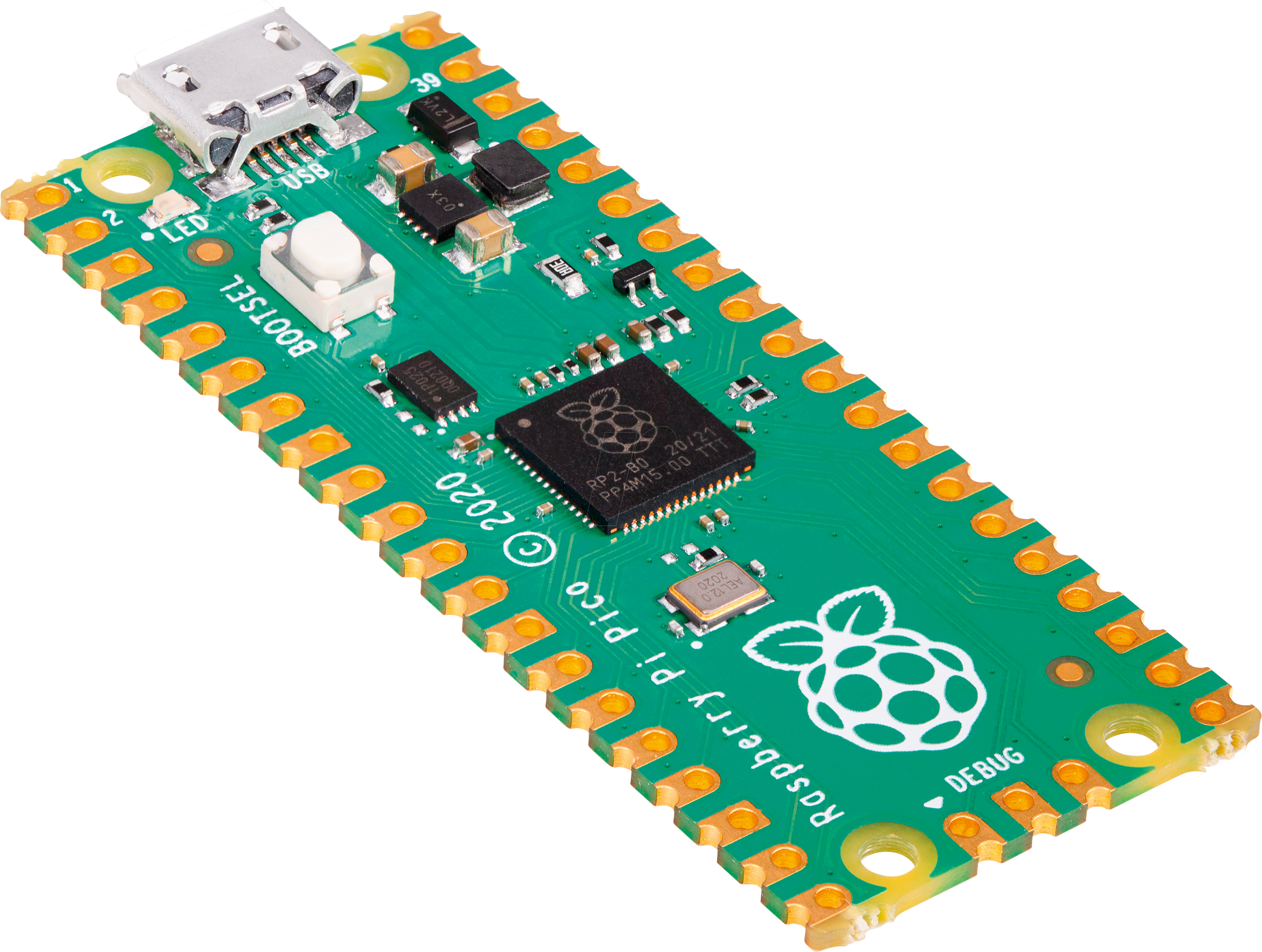
Raspberry Pi Pico is a great microcontroller from the Raspberry PI foundation. It has very interesting capabilities as
- 133MHz dual ARM Cortex-M0+ cores
- 264kB SRAM in six independent banks
- Support for up to 16MB of off-chip Flash memory via dedicated QSPI bus
- DMA controller
- Fully-connected AHB crossbar
- Interpolator and integer divider peripherals
- On-chip programmable LDO(Low-dropout_regulator) to generate core voltage
- 2 on-chip PLLs to generate USB and core clocks
- 30 GPIO pins, 4 of which can be used as analog inputs
It can be used to drive VGA displays, do multi-threaded processing, etc. In this instructable we will explore how to connect Raspberry PI Pico to NodeMCU with I2C communication Protocol with NodeMCU as a Slave.
Supplies
- Raspberry Pi Pico
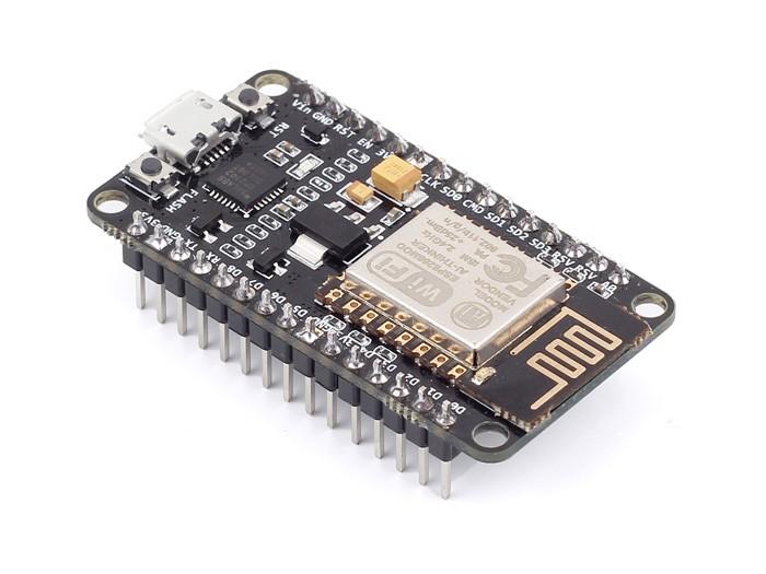
- NodeMCU
Wiring/Connections
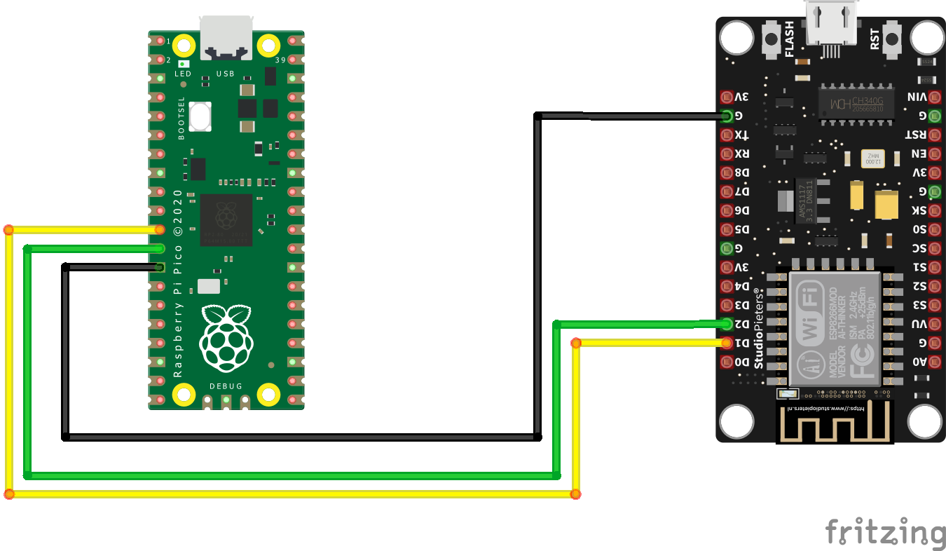
To connect the Raspberry Pi Pico to NodeMCU
- Connect D1 of NodeMCU to GP8 of Raspberry PI Pico
- Connect D2 of NodeMCU to GP9 of Raspberry PI Pico
- Connect GND line on both for a common ground
Check the above image to cross-check your connections. No need to worry here as the connections are simple.
Software
Raspberry Pi Pico can be programmed in Micropython, CircuitPython and C++. We will be programming it with MicroPython with Thonny IDE. I recommend going through Raspberry Pi foundation's getting started guide. Also, you may need to flash your Pico before using it for the first time. it can be done by holding the BOOTSEL key down on Pico before plugging it into your PC. Now the Pico will be attached to your PC as a flash drive. Drag and drop through a file explorer the downloaded .UF2 file onto the new flash drive that is the Pico. After having flashed, the Pico will eject itself from the computer and reboot. Now it is time to install Thonny. Download from the below link the Thonny executable. After installing, open the ide and click the bottom left-hand corner's box and select "Configure interpreter". When the menu appears, make sure the top drop-down box is set to "MicroPython (Raspberry Pi Pico)". With this, you are now set to program the Pico with MicroPython!
Here are the download links:
Code
This code is split into two parts: one will run on the Raspberry Pi Pico while the other will run on NodeMCU.
As mentioned above Raspberry Pi Pico is programmed using Thonny IDE, this is the code:
#Code for Raspberry Pi Pico
import utime
import machine
from machine import I2C

I2C_ADDR = 0x08 #I2C Address of NodeMCU
data = "Some data to send" #Data to send to I2C device

def main():
    print("Initalizing I2C as Master")
    i2c = I2C(0, sda=machine.Pin(8), scl=machine.Pin(9), freq=10000)


    i2c.writeto(I2C_ADDR, data) #This line is responsible for sending data
                                #the above function can be called multiple times, changing
                                #the I2C_ADDR to transmit to various devices on the bus
                                #also changing the data variable will change the data being transmitted
    utime.sleep_ms(50)

main()
In the above code the line
i2c.writeto(I2C_ADDR, data)
is responsible for sending the data over the i2c bus, here I2C_ADDR is the address of the device and data is the data is data being send over I2C.
Code for NodeMCU using Arduino IDE:
#include <Wire.h>

#define SDA_PIN D1         //Declare SCL Pin on NodeMCU
#define SCL_PIN D2         //Declare SDA Pin on NodeMCU

const int16_t I2C_SLAVE = 0x08;

void setup() {
  Wire.begin(SDA_PIN, SCL_PIN, I2C_SLAVE);  // join i2c bus with address #8
  Wire.onReceive(receiveEvent);             // register event
  Serial.begin(115200);                     // start serial for output
}

void loop() {
  delay(100);
}

// function that executes whenever data is received from master
// this function is registered as an event, see setup()
void receiveEvent(int howMany) {
  while (1 < Wire.available()) { // loop through all but the last
    char c = Wire.read(); // receive byte as a character
    Serial.print(c);         // print the character
  }
}
Upload the above code on the NodeMCU using Arduino IDE, When done uploading open Serial Monitor and set the baud rate to 115200. The data being transmitted will get printed on the Serial monitor. Now modify the code for your program.