Hydrogen Water Electrolysis Setup for Educational Use
by Saxion University of Applied Sciences in Teachers > University+
631 Views, 4 Favorites, 0 Comments
Hydrogen Water Electrolysis Setup for Educational Use
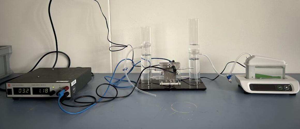
The Sustainable Energy System research group at Saxion University of Applied Sciences has developed a water electrolysis setup. Purchasing a complete commercial electrolysis setup can be costly, but buying the individual components separately is a more affordable option. Interested users can easily purchase these components online and complete the setup themselves.
The setup is straightforward and consists of three main components: a power supply, a PEM electrolyser, and a gas measurement device. Detailed information about the components and setup process can be found in the following sections.
Water electrolysis is the process of splitting water into oxygen and hydrogen using electrical energy. In this setup, the power supply provides electricity to the electrolyser, where water splitting takes place. The hydrogen produced in the electrolyser is then directed to the gas measurement device to measure the volume of gas generated.
Supplies
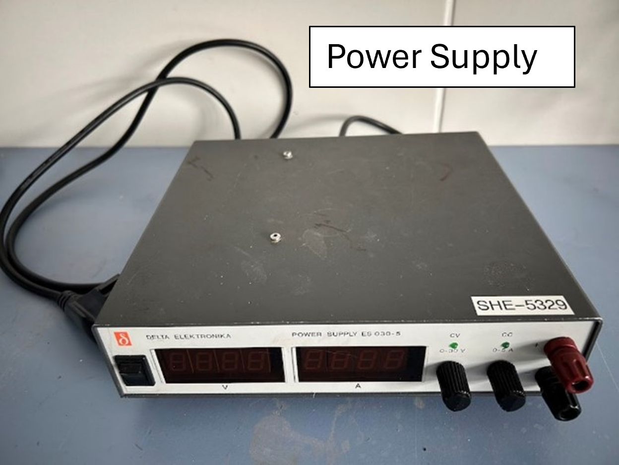
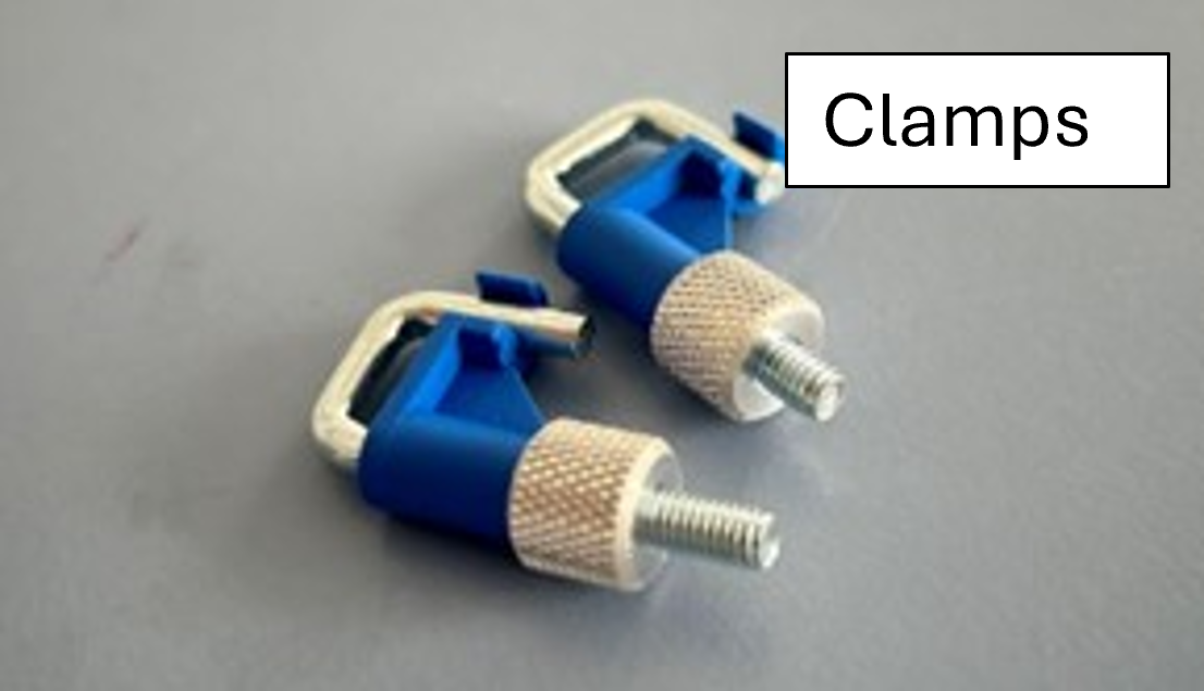
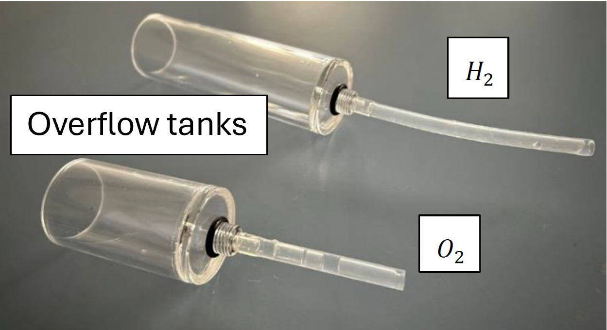
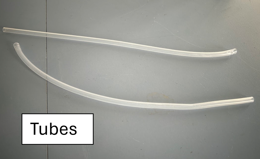
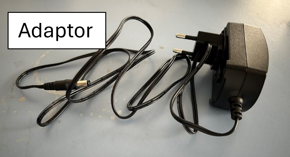
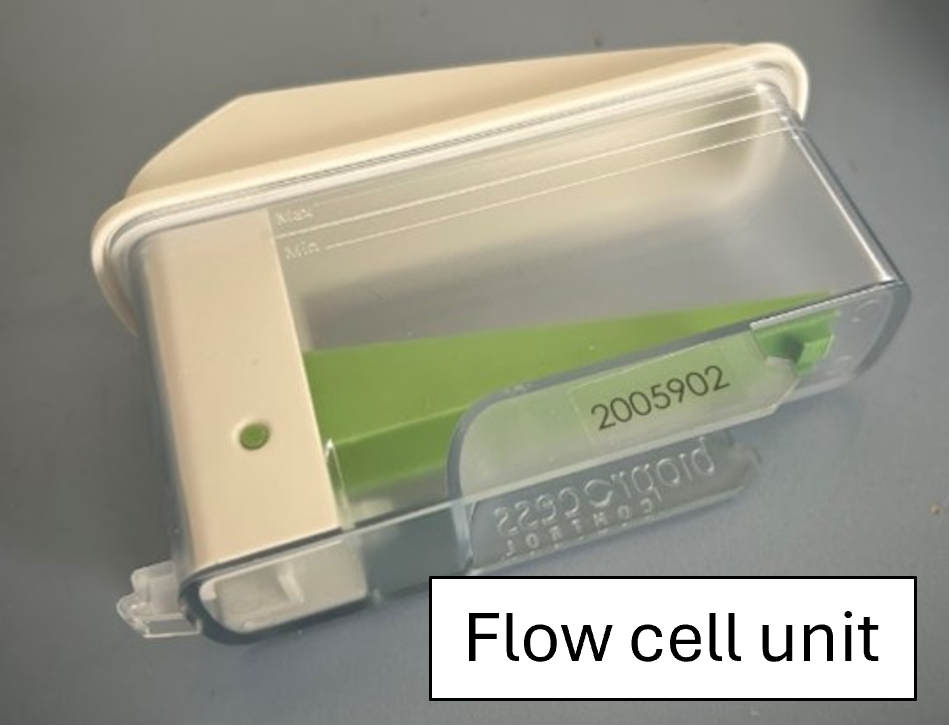
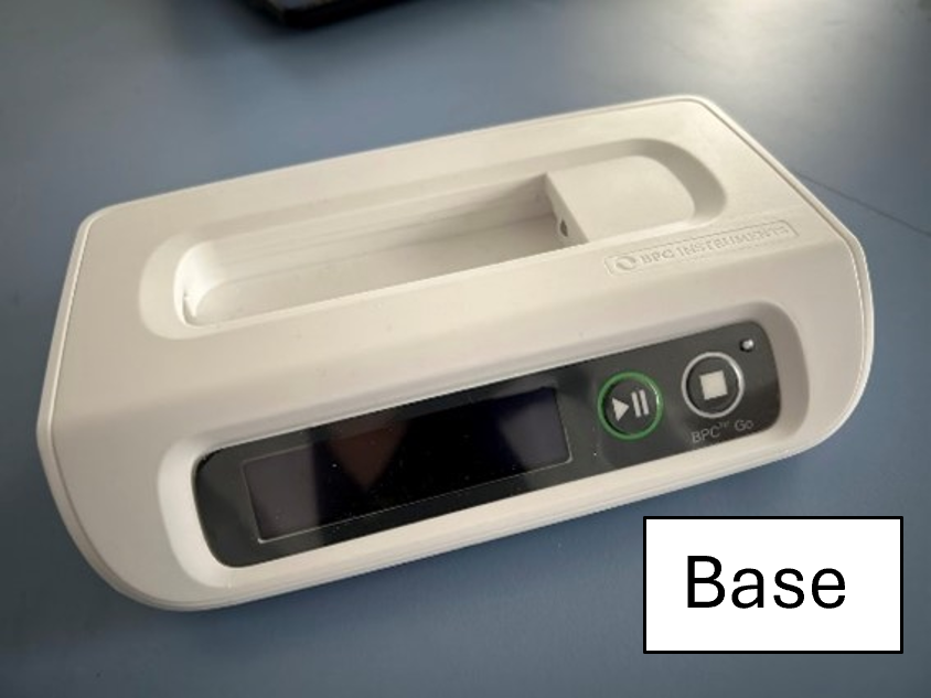
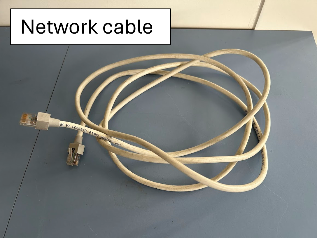
- Power supply (1 unit): provides electricity to the electrolyzer
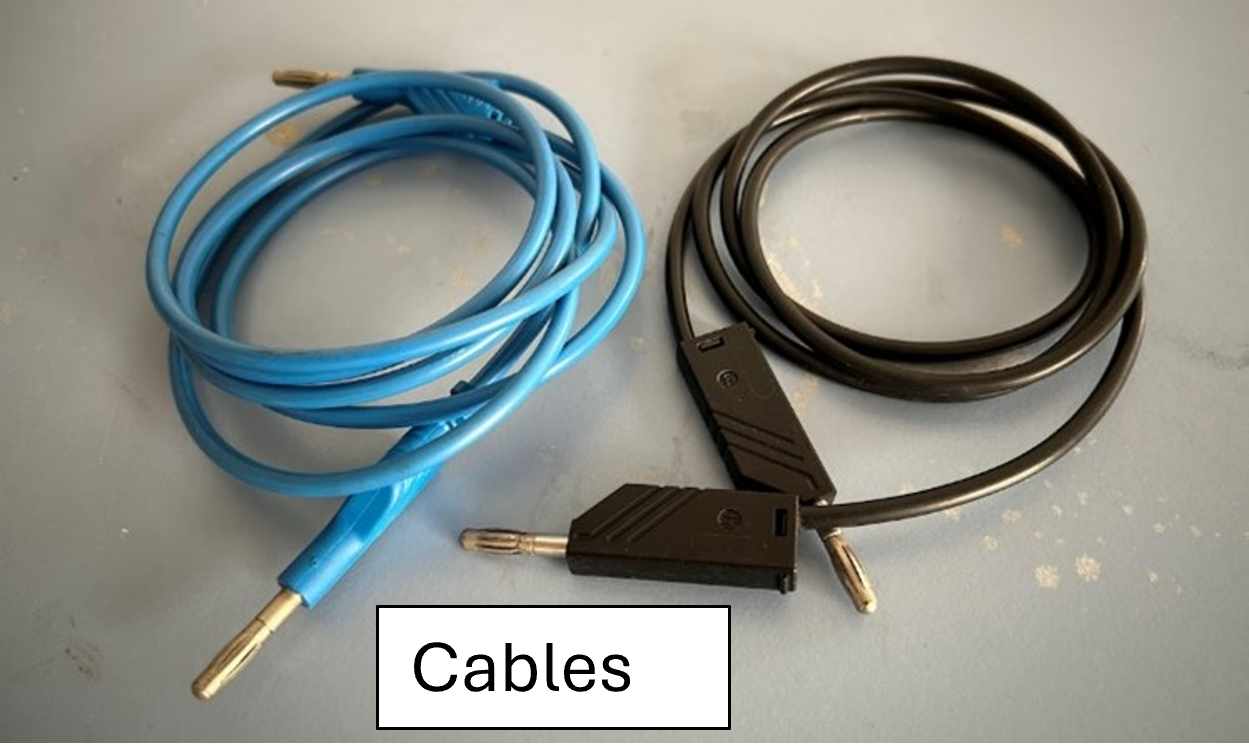
- Cables (2 units): connect the power supply to the electrolyzer
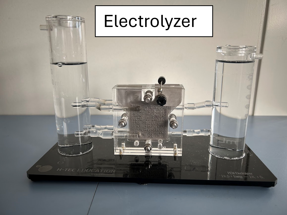
- Electrolyser (1 unit): splits water into hydrogen and oxygen
- Clamps (2 units): prevent gas from escaping
- Overflow tanks (2 units): serve as water reservoirs
- Hydrogen tank (1 unit)
- Oxygen tank (1 unit)
- Tubes (2 units): serve as a connection of gas outlets and can be used to connect the electrolyzer to the gas measurement device
- Gas measurement device - BPC Go (1 unit): measures the amount of produced gas.
- Adaptor (1 unit)
- Flow cell units (2 units): with different volumes which are 2 ml and 9 ml
- Base (1 unit)
- Network cable
Main component details:
- Power supply-ES150 SERIES
- Supplier: Delta Elektronic
- Price: 500 €
- Electrolyzer - Electrolyzer 65 (Double-Cell PEM electrolyzer stack)
- Supplier: Fuel Cell Store
- Price: 330 €
- Manufacture: H-TEC Education
- BPC Go
- Supplier: BPC instruments
- Price: 2780 €
Attaching the Tubes and Clamps to the Electrolyser
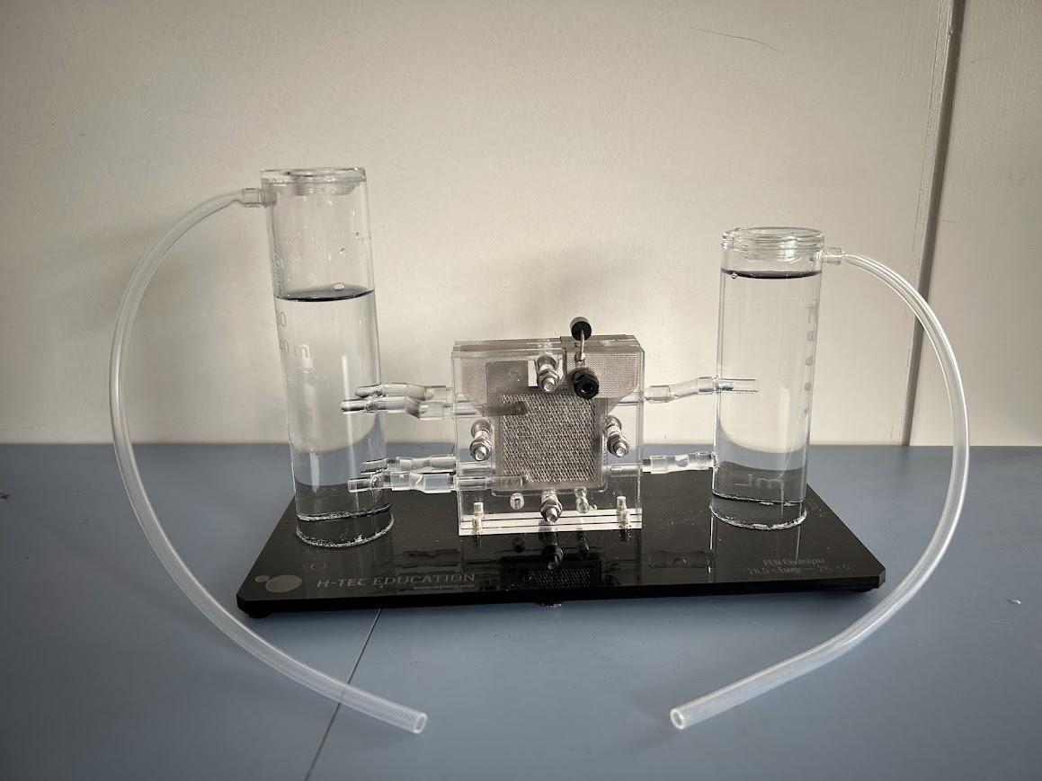
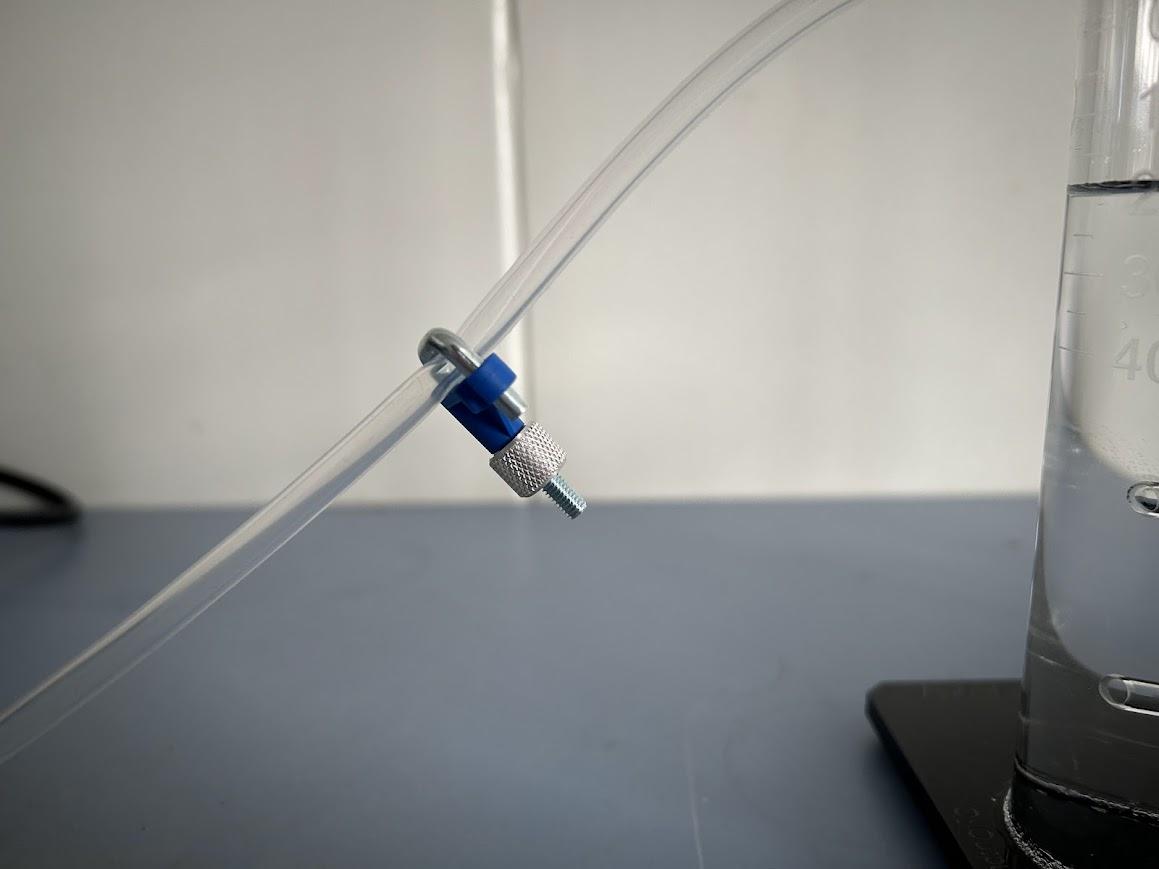
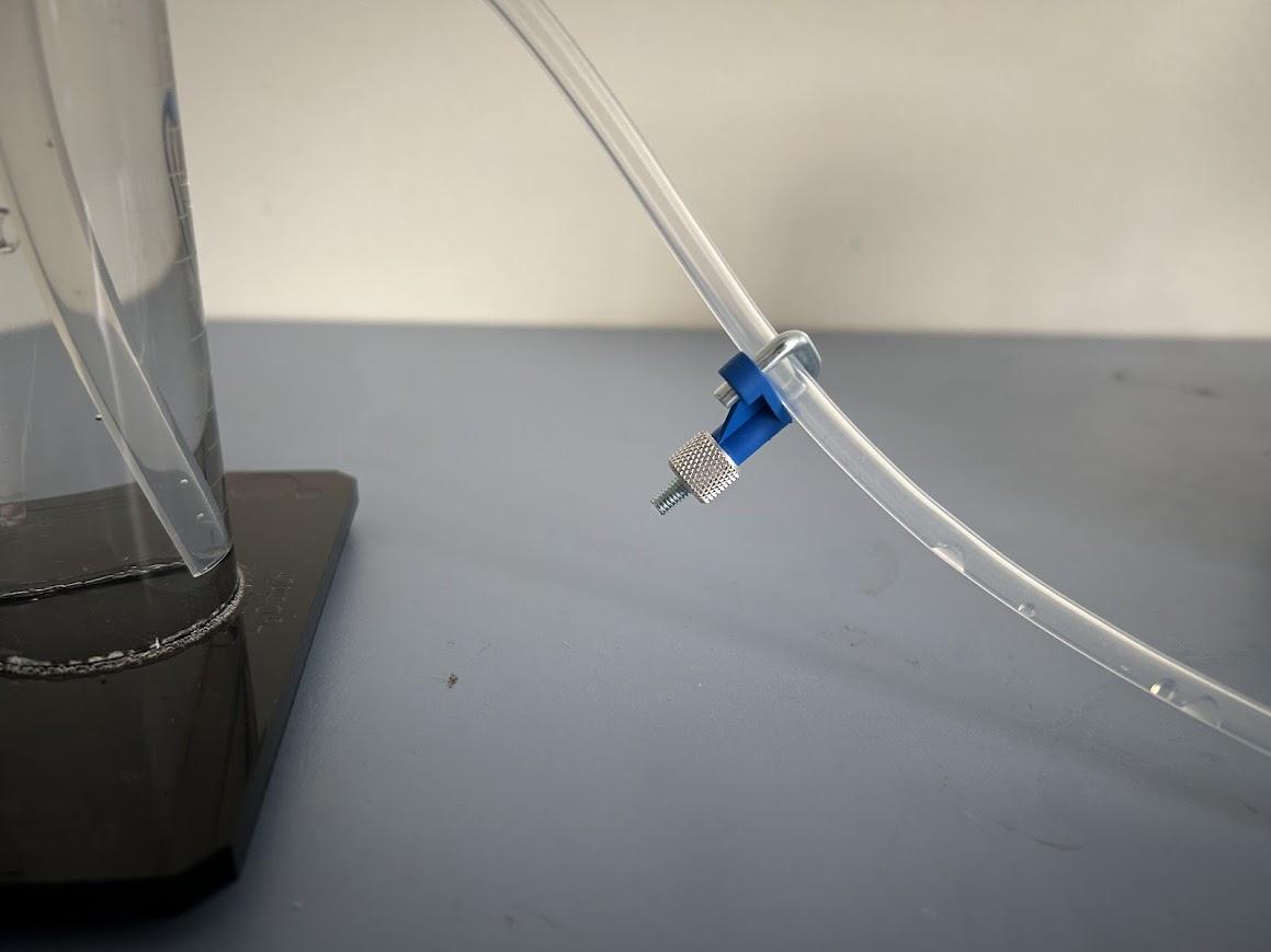
- Components needed: 2 tubes, 2 clamps and electrolyser.
- Instructions:
- Attach a tube on both hydrogen and oxygen outlets.
- Attach a clamp to both the hydrogen and oxygen outlet tubes (but do not close the clamp on the hydrogen side).
Attaching the Overflow Tanks to the Electrolyser
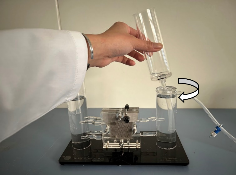
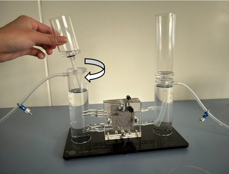
- Components needed: Electrolyser and 2 overflow tanks.
- Instructions:
- Connect the longer overflow tank to the hydrogen side (the shorter fixed tube on the electrolyser).
- Connect the shorter overflow tank to the oxygen side (the longer fixed tube on the electrolyser).
Connecting the Power Supply
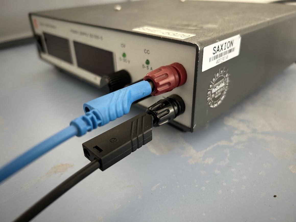
- Components needed: Power supply and 2 cables.
- Instructions:
- Connect one cable to the red terminal and the other cable to the black terminal of the power supply.
Connecting the Electrolyzer to the Power Supply
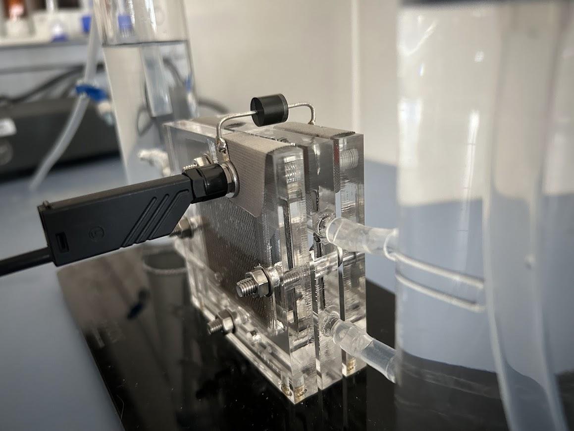
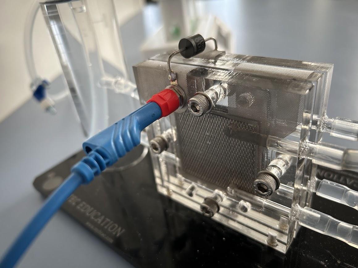
- Components needed: 2 cables and electrolyzer.
- Instructions:
- Connect the cable from the black terminal of the power supply to the black terminal on the electrolyzer, and the cable from the red terminal to the red terminal on the electrolyzer.
Adding Water to the Gas Measurement Device
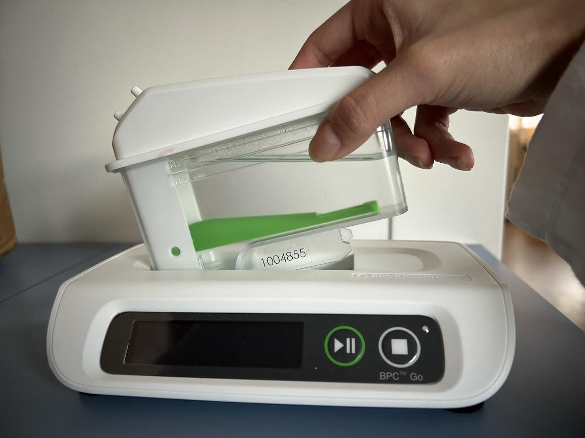
- Components needed: Flow cell unit and the base
- Instructions:
- Connect a flow cell unit to the base
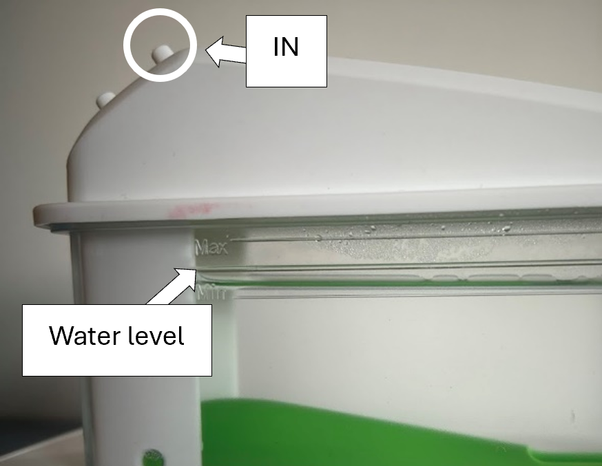
- Gas measurement device: add distilled water to the level to reach the line between ‘Max’ and ‘Min’. Use a syringe to fill the flow cell unit via the "IN" port.
Adding Water to the Electrolyzer
- Components needed: Electrolyser.
- Instructions:
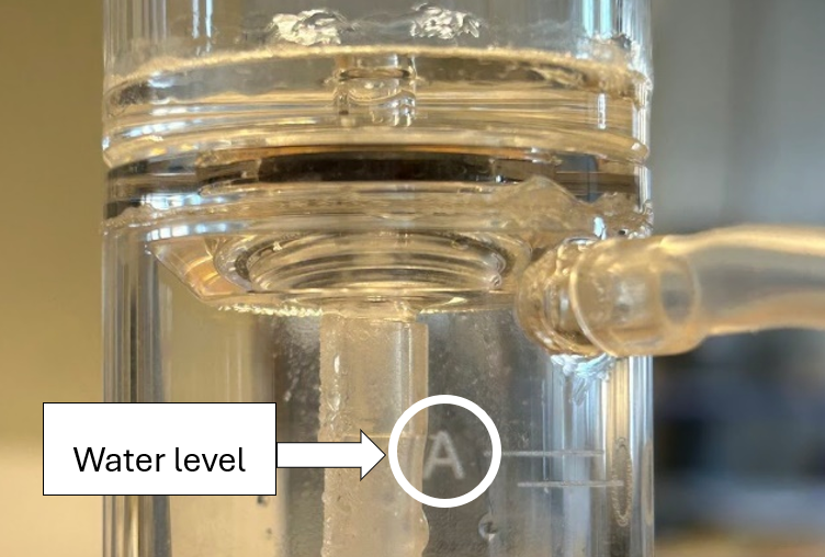
- Electrolyser: add the distilled water to the level that reaches ‘A’ in the electrolyser for both the hydrogen and oxygen sides.
Connecting the Electrolyzer to the Gas Measurement Device
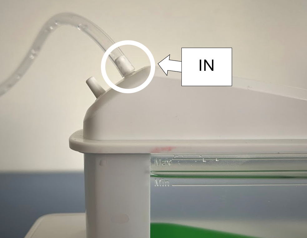
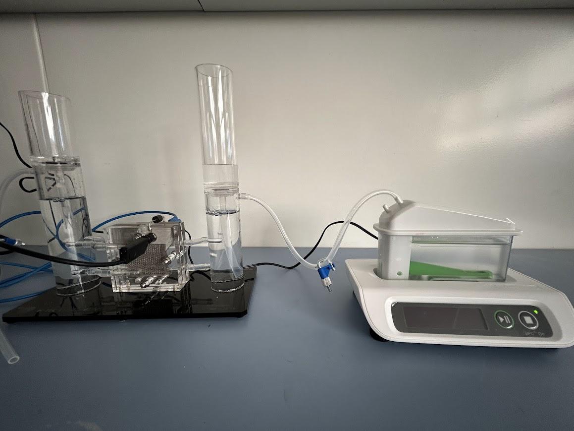
- Components needed: Hydrogen outlet tube and gas measurement device.
- Instructions:
- Connect the hydrogen outlet tube to the ‘IN’ port of the gas measurement device.
Connecting the Data Measured From the Gas Measurement Device to a Laptop
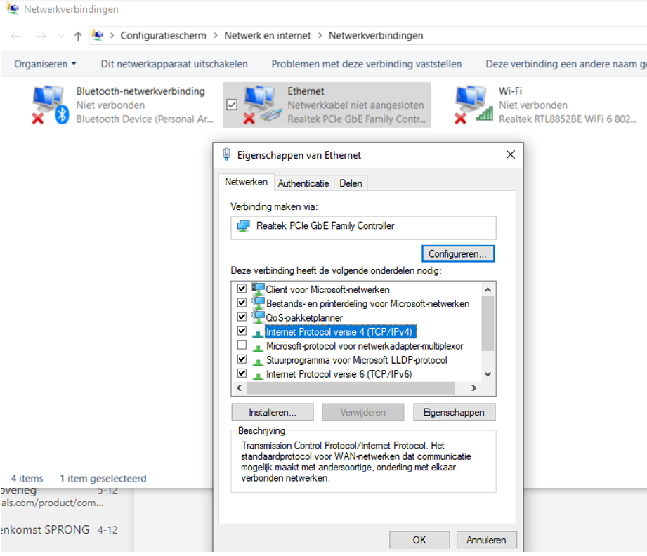
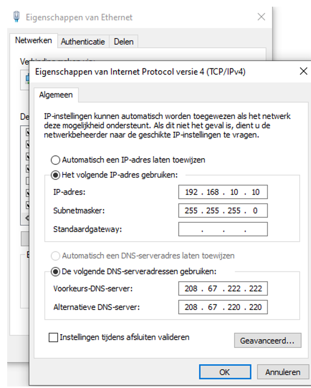
- Components needed: Network cable and a laptop
- Instructions:
- Plug the network cable from the gas measurement device into the laptop.
- Go to the Settings on your Windows computer and open Network & Internet.
- Select the right ethernet connection. Go to the Advanced Network Setting and select the correct network. Then go to More Adapter Options and the tab in the left picture can be found.
- Press Internet Protocol version 4 (TCP/IPv4) fill in the numbers in the right picture and save them.
Accessing to the Software
- Type 192.168.10.11 into the address bar at the top of your browser, then press Enter.
- When you have a connection to the gas measurement device you see the following: BPC Instruments | BPC Go | BPC Instruments
- Fill in the password
The Software
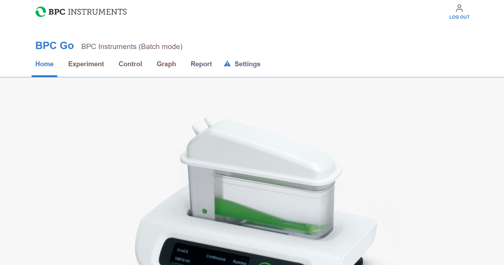
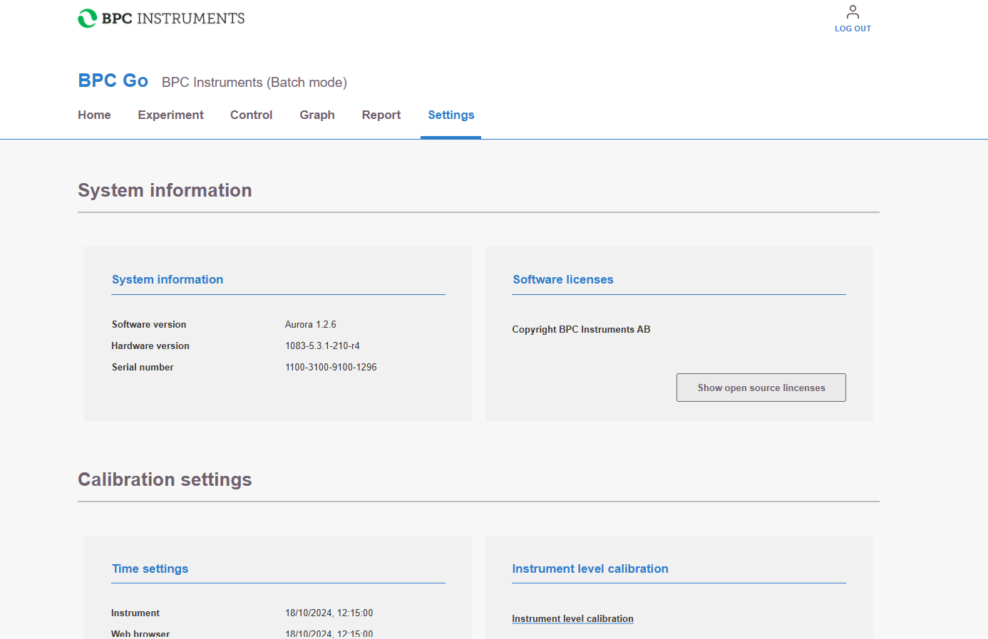

- After logging in, the menu in the first picture is shown.
- Go to the Settings menu, synchronize the computer, and calibrate the device.
The Software
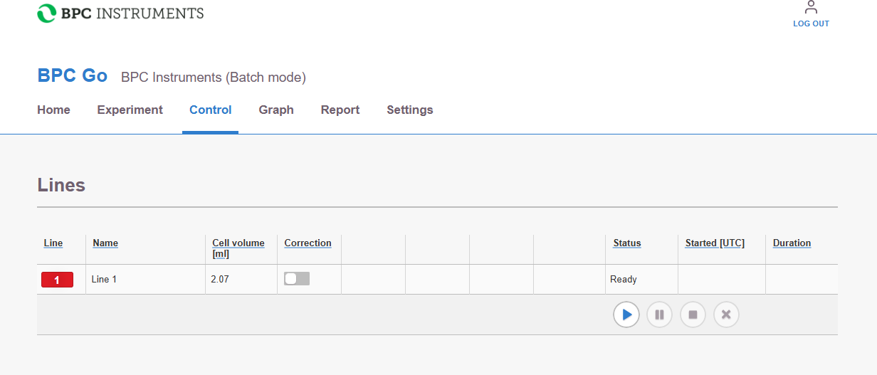
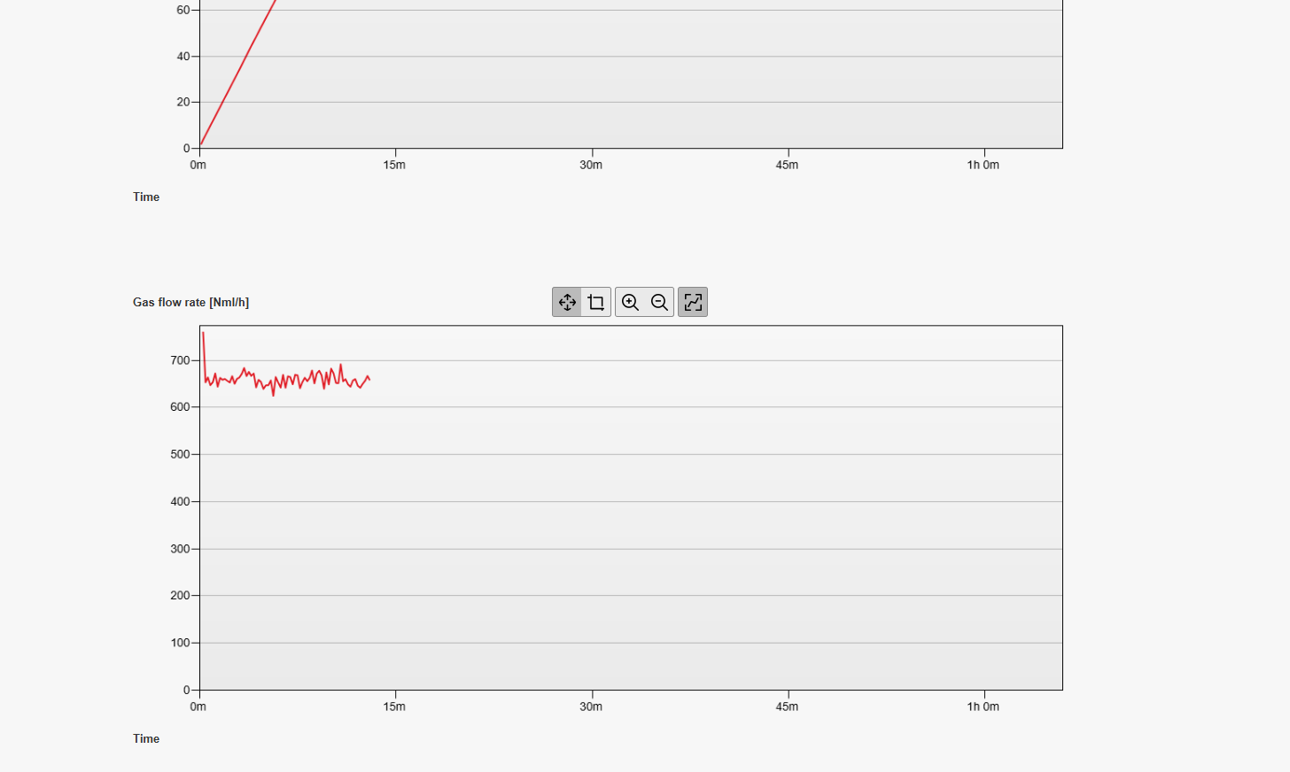
- Press on the play button in the Control screen so the flow measurements start being recorded.
- There is a Graph screen where you can see the flow measurements.
The Software
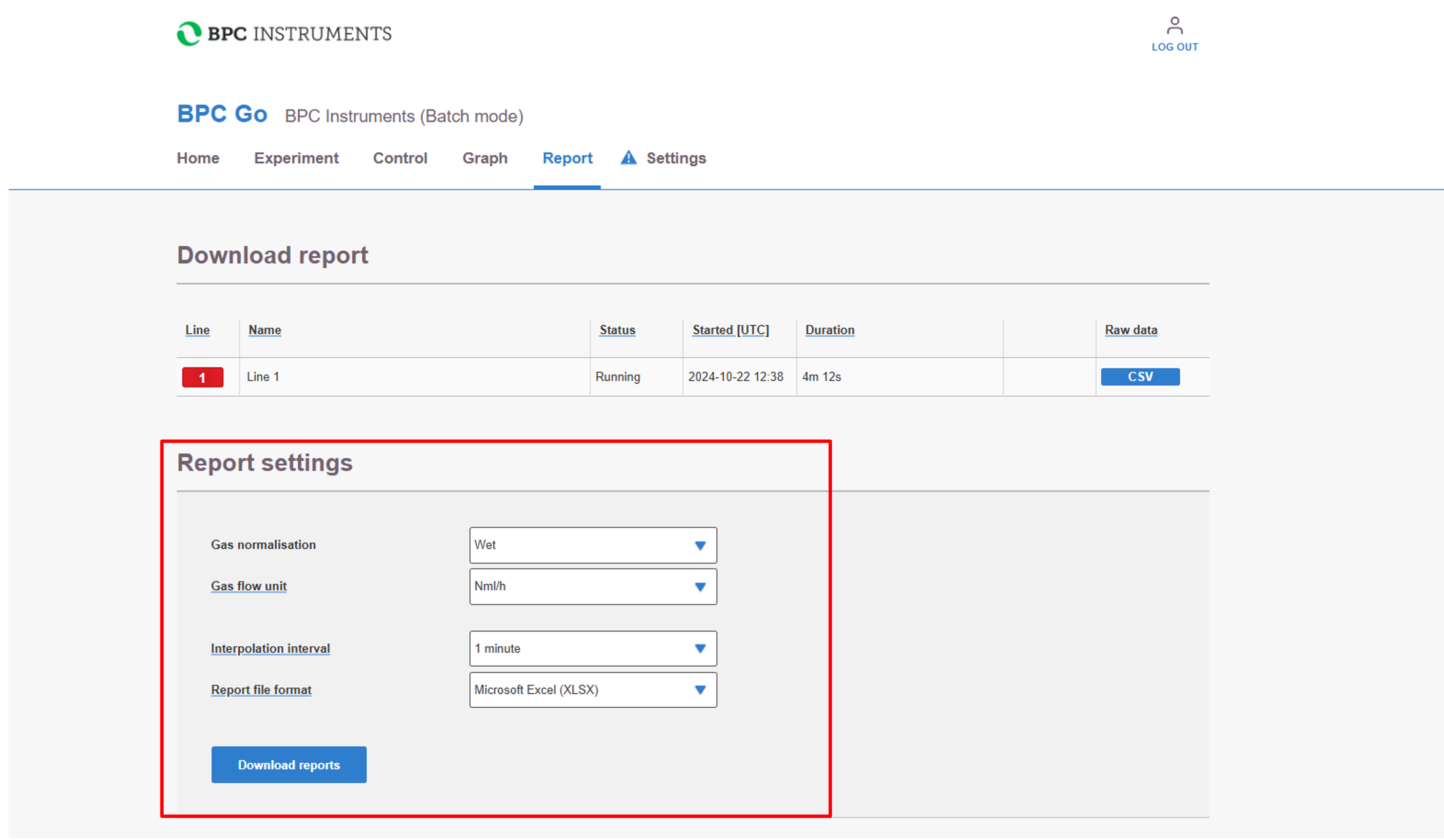
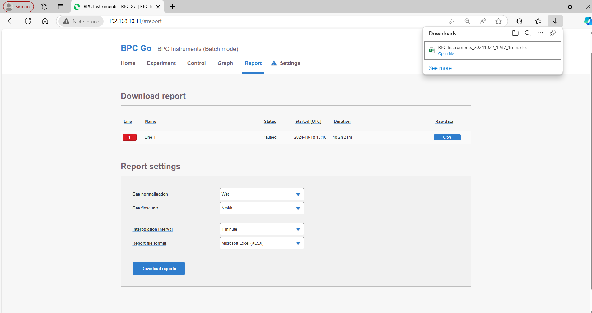
a. The measurements can be downloaded via a CSV file.
Components Protection (Optional)
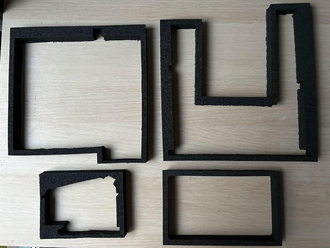
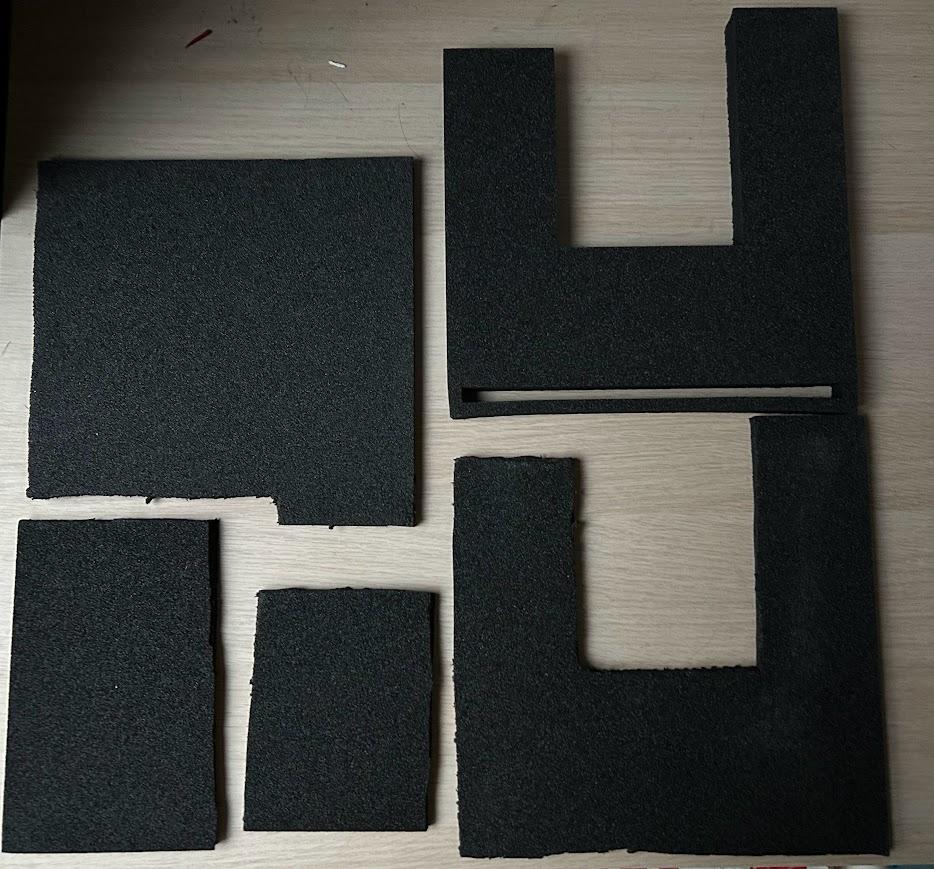
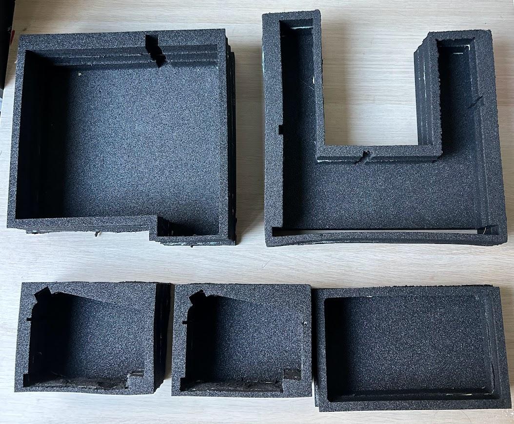
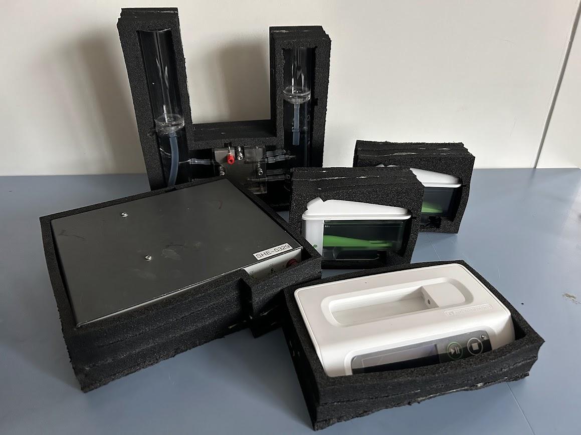
Since the components are fragile, there is a high risk of damage during transportation; therefore, it would be useful to have some protection packing. The attachments include the vector files for laser cutting each component. PE foam has been chosen as the prototype material since it is safe for laser cutting. After laser cutting the foam, the layers can be glued together with an appropriate adhesive, specifically for foam. The thickness specifications of the foam are indicated in the document names.
Final Check Before Operating
- Are the red and black terminals connected correctly to the power supply and electrolyser?
- Are the overflow tanks connected correctly to the hydrogen and oxygen sides on the electrolyser?
- Is the hydrogen outlet clamp open?
- Is the hydrogen tube correctly connected to the gas measurement device?
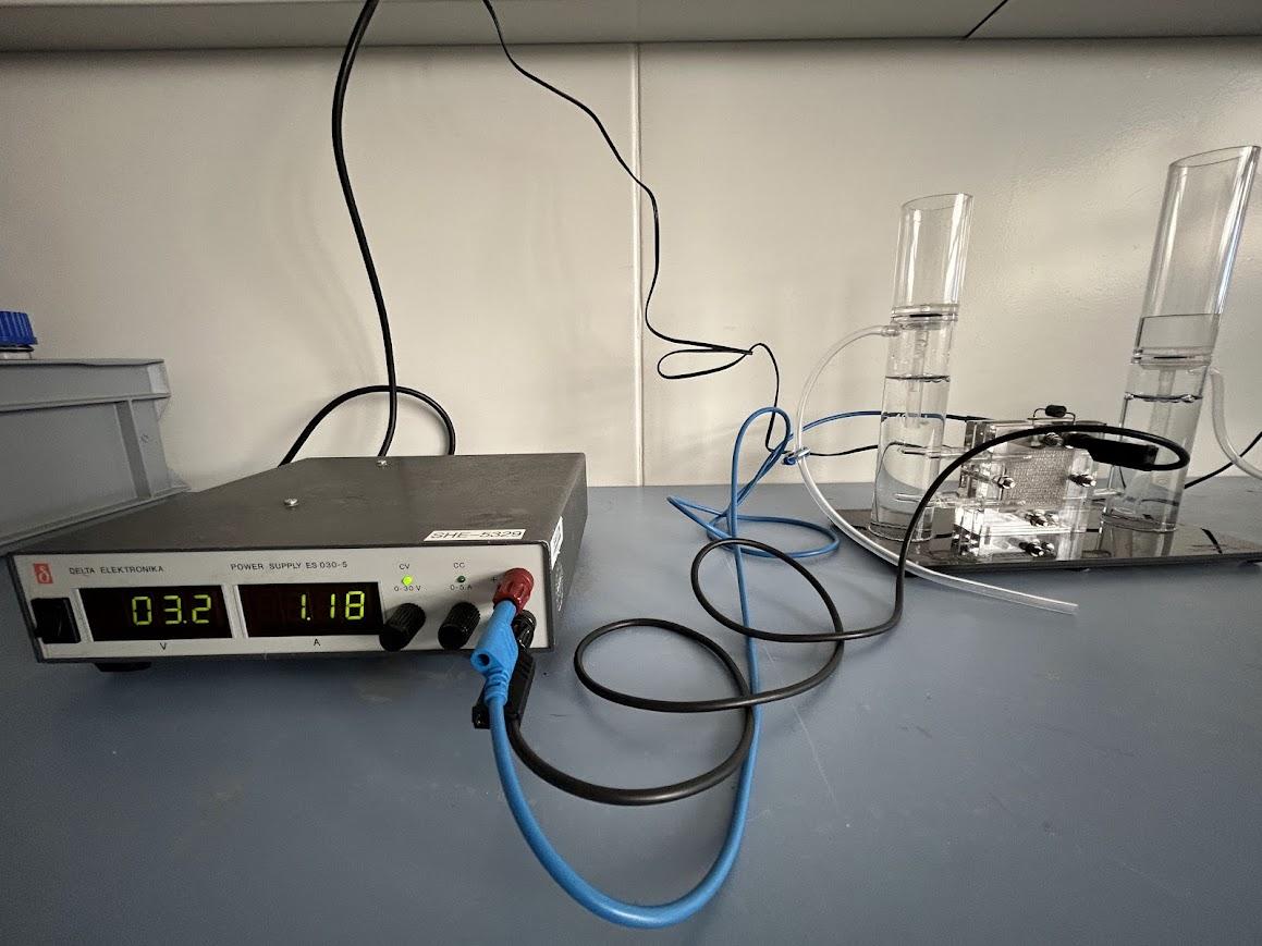
The Completed Setup
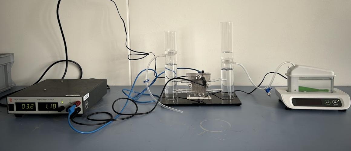
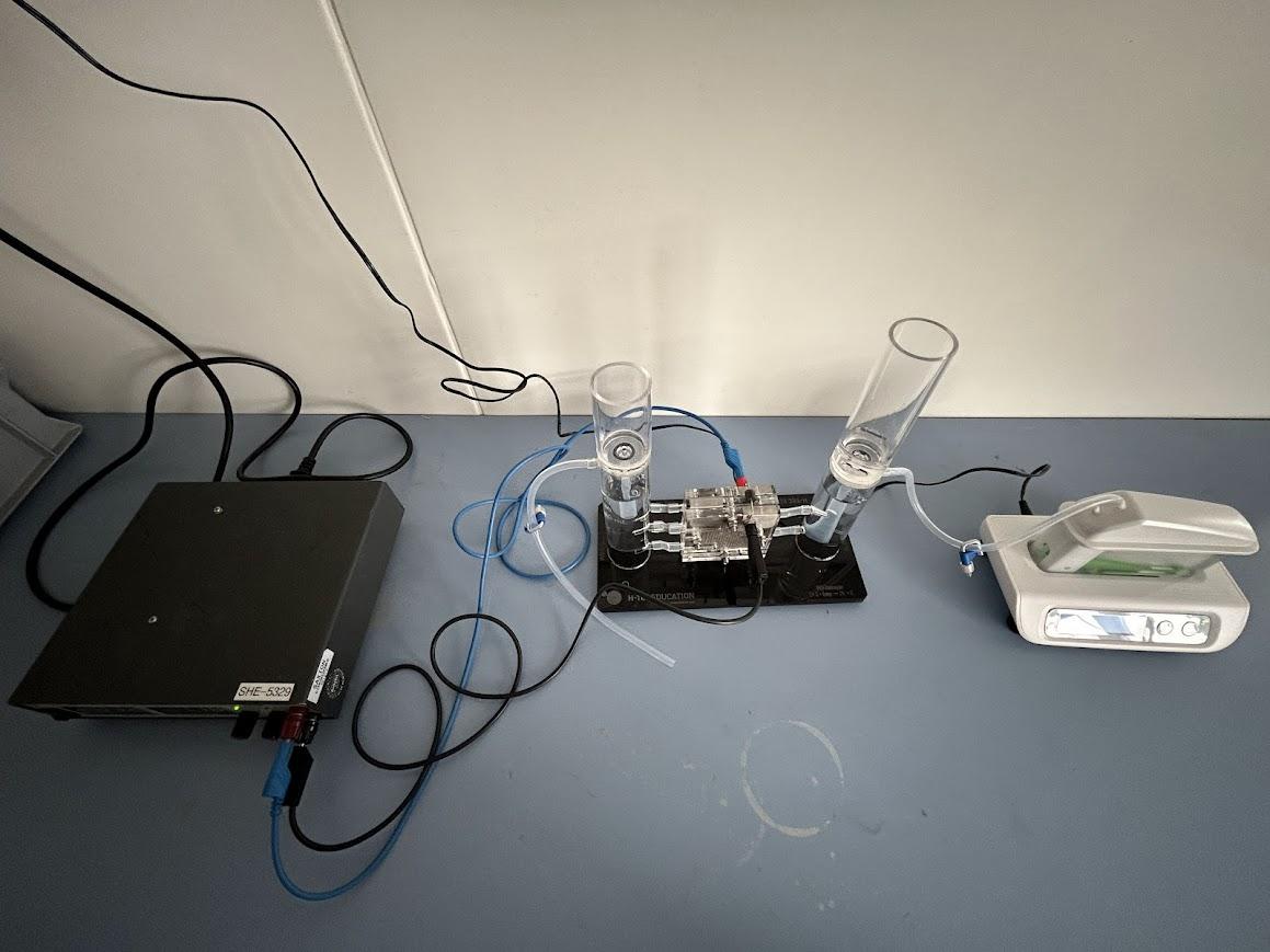
Start the Operation:
Turn on the power supply and ensure that the voltage and current remain within the permissible range.
- Permissible Operating Voltage: 0 - 4 VDC
- Permissible Operating Current: 0 - 4.4 A