Hybrid Manufacturing With Fusion 360 and Snapmaker 2.0
by Brien Allison in Workshop > CNC
3694 Views, 24 Favorites, 0 Comments
Hybrid Manufacturing With Fusion 360 and Snapmaker 2.0
Hybrid manufacturing is an emerging process which combines additive (e.g. 3D printing) and traditional subtractive manufacturing processes (e.g. milling) in a single machine. Although in an industrial context, hybrid manufacturing specifically uses both processes in a single manufacturing step, this instructable technically isn't hybrid manufacturing since it's an additive step followed by a subtractive step, but both processes were done on a single machine so hey, it's close enough.
Also this project was produced entirely with just Fusion 360 and a Snapmaker 2.0 A150, no other software or machines were used for this project (except for a Prusa mini to speed things up a bit).
This is also my first forray into CNC machining so you could also title this "How NOT to do hybrid manufacturing with Fusion 360 and Snapmaker 2.0" and mistakes were made, so hopefully this helps other newbies out or is at least amusing to some people.
This instructable documents the general process of how I used Fusion 360 to produce a straight edge for my machine, and then used it to accurately manufacture a gear printed from Nylon (Taulman Alloy 910) and machined to its final shape.
Supplies
A 3D printer and material.
A CNC machining... machine.
Spare bits to replace those you will inevitibly break.
A lot of patience.
Design Your Object
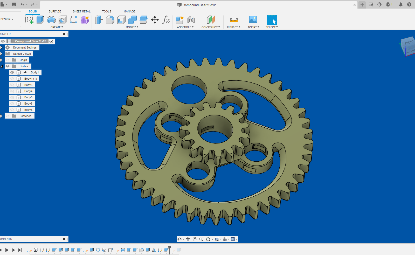
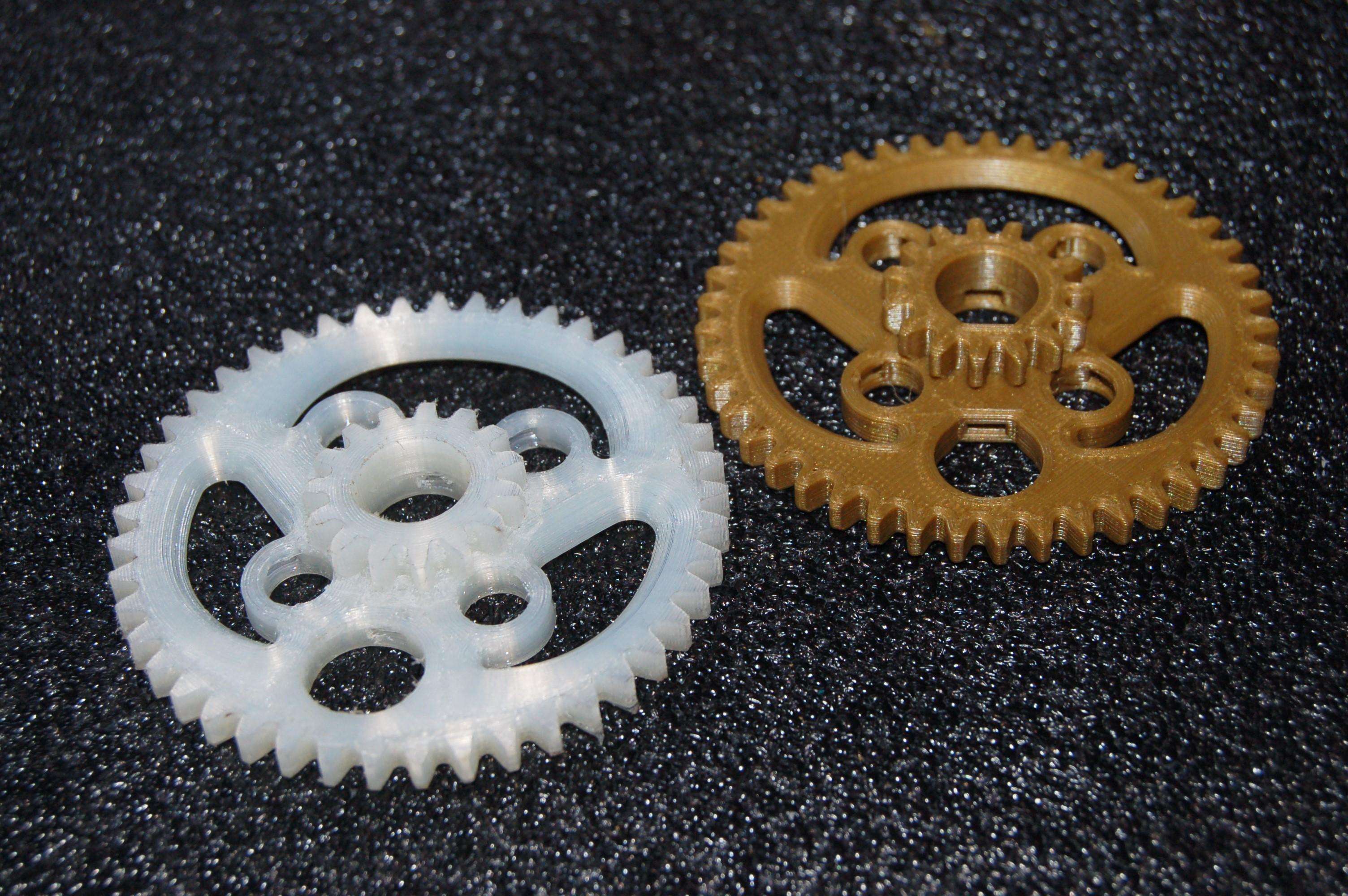
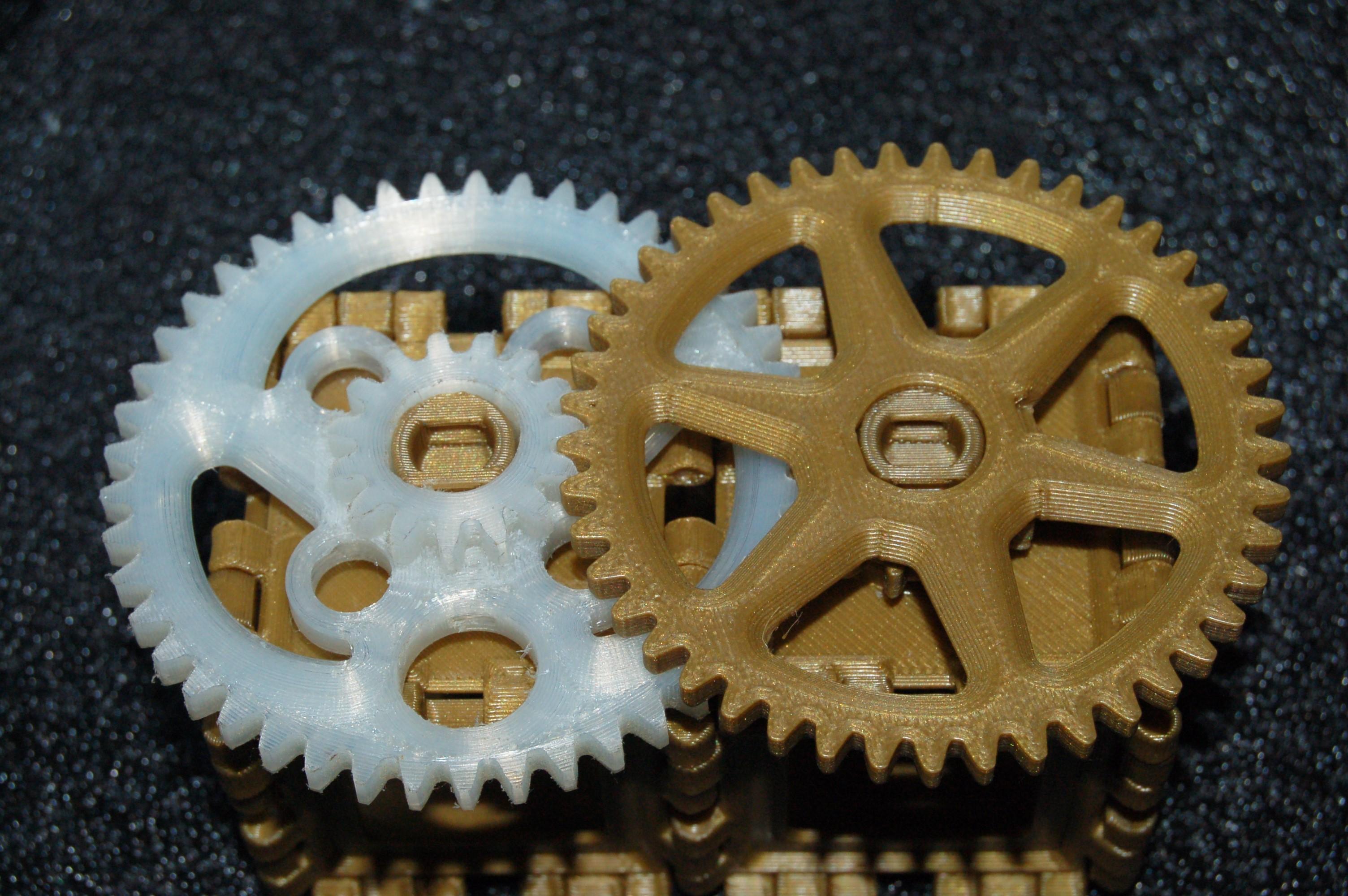
The final goal of this project was to produce a compound gear (two gears joined together) where the the important mechanical load bearing surfaces were machined to a good finish. 3D printed gears work well for simple mechanical devices (including some 3D printer extruders!) but fall short where more performance or precision is needed.
While it would be possible to produce this part with just CNC machining, it would need to be split into several parts (there are horizontal channels within the large gear which would be impossible to cut from a single stock of material) and produce a lot of waste material. Here a hybrid approach can achieve the best of both processes, geometric freedom of additive and precision of subtractive.
Fusion 360 was used to produce the part in the design workspace and this is where it would stop for most design projects. The files would likely be downloaded to other software packages such as slicers to produce the final part. I realised since Fusion has recently incorporated a slicer into the program, that the entire process could be done within fusion (hence the name, fusing many program features into one).
Plan the Manufacturing Process
The first issue that springs to mind with hybrid manufacturing, is alignment of the part between the different processes. With CNC routing, it often doesn't really matter how the stock is aligned, as long as it's held down securely, and the desired object can be cut from the stock. With Hybrid manufacturing however, alignment of the printed part is critical to ensure the machined features are produced in the correct positions.
One approach is where the printed part remains fixed to the print bed throughout the process, so its location in the machines co-ordinate system is fixed. This requires a specialised machine, such as the 'Tool Changer' from E3D or the more expensive industrial CNC machines with additive 'tools' retrofitted or built into them from the start. Currently these specialised machines are not in the arsenal of the average maker (for now).
Most will have separate additive and a subtractive machines rather than a hybrid one. In this case I am using a Snapmaker 2.0 A150 which technically can do additive and subtractive in one machine, but requires manual retooling, including the bed surface; so it is essentially two separate machines in that respect.
Alignment of the printed part requires both squaring it (align rotational degrees of freedom) and setting the correct origin on the part (align translational degrees of freedom). Both additive and subtractive machines would need to be calibrated to produce a part with accurate dimensions but in this case the same machine is used for each process.
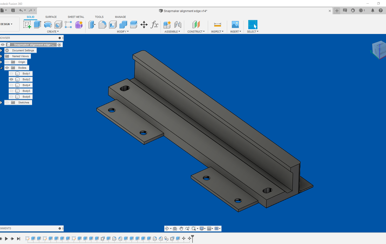
The transIational degrees of freedom are aligned when setting the work origin for the process. But in order to align the rotational degrees of feedom I designed a square alignment edge for the Snapmaker in Fusion 360.
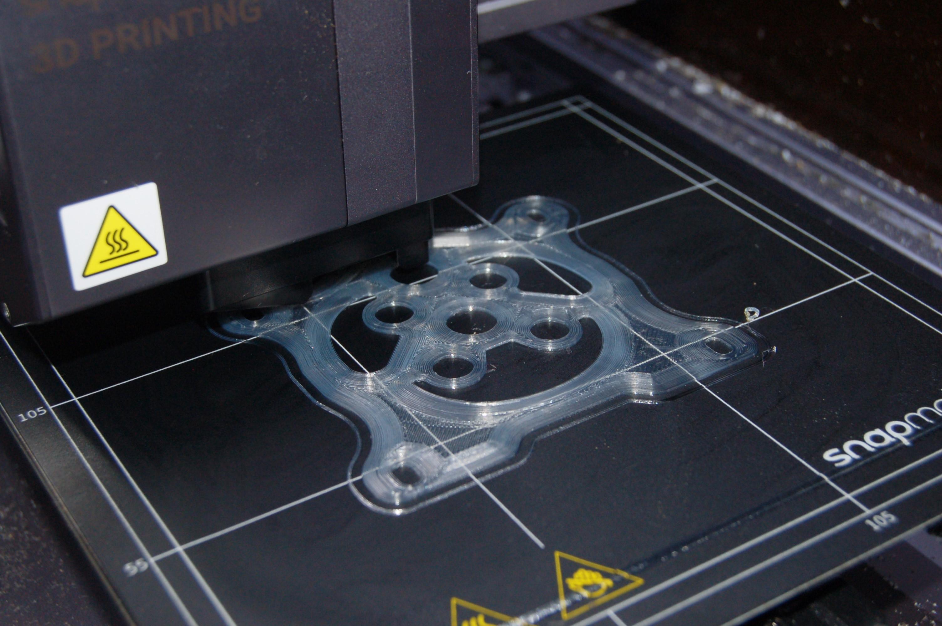
Print the Square Edge
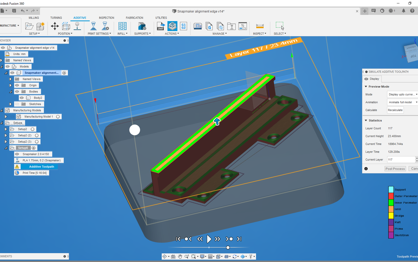
To print the part I used the Fusion 360 additive function in the manufacture workspace:
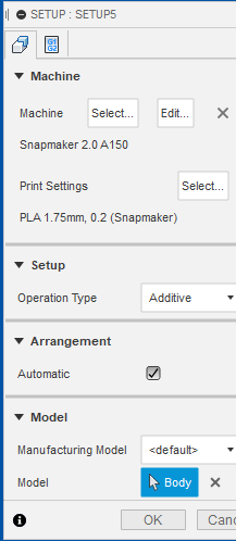
- Select 'Setup' from the toolbar. A small dialog should open with different options to setup the process.
- In 'Operation type' select 'Additive'.
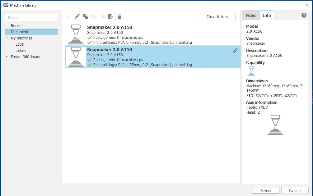
- In 'Machine' click 'Select'. This will open the machine selection library. Some machines are already included in the Fusion 360 machine library including the Prusa Mini + which I used to print this part.
- If your machine is not included in the library, select any other machine and use the copy and paste icons (on the top toolbar) to move it into your 'Local' folder in the file tree on the left side of the window.
- Click the little pen icon to edit the machine settings including the dimensions of the printing envelope and temperature limits. You will also need to choose a post processor; for many machines e.g. Prusa, there are post processors to choose from the provided list. In the case of the Snapmaker, there is no specific post processor but I used 'generic fff machine' from the list and that worked fine.
- Select the configured machine and click the select button in the bottom right corner.
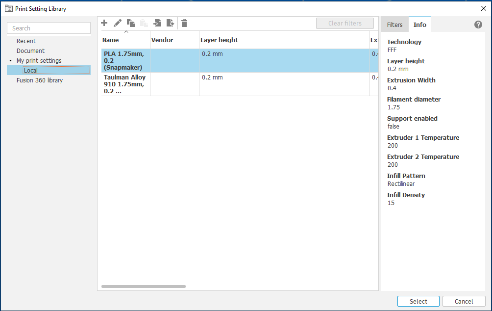
- Now click select the print settings button. You will be shown a similar dialog box as before but with a library of materials. There are some premade profiles, but you will likely want to edit them for your own preferences. The slicer in Fusion is simpler than the common Slicer programs e.g. Prusa Slicer, Cura. But it doesn't have some of the more advanced features at the moment e.g. ironing.
- Once you have selected a material profile, you can then select the model you want to print in the 'model' subsection.
- You can also tick the 'Automatic' checkbox in the arrangement subsection to automatically arrange the parts on the print bed.
- Click 'Ok' to close the Setup dialog box.
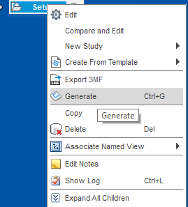
- Right click the setup in the tree on the right hand side and click 'Generate' (or Ctrl + G) to generate the additive process.
- If you are happy with the setup. Click on the 'Post process' button.
- This will open the post processing dialog. Select the post processor which is appropriate e.g. 'generic fff machine .cps' then click 'Post' and save the gcode file.
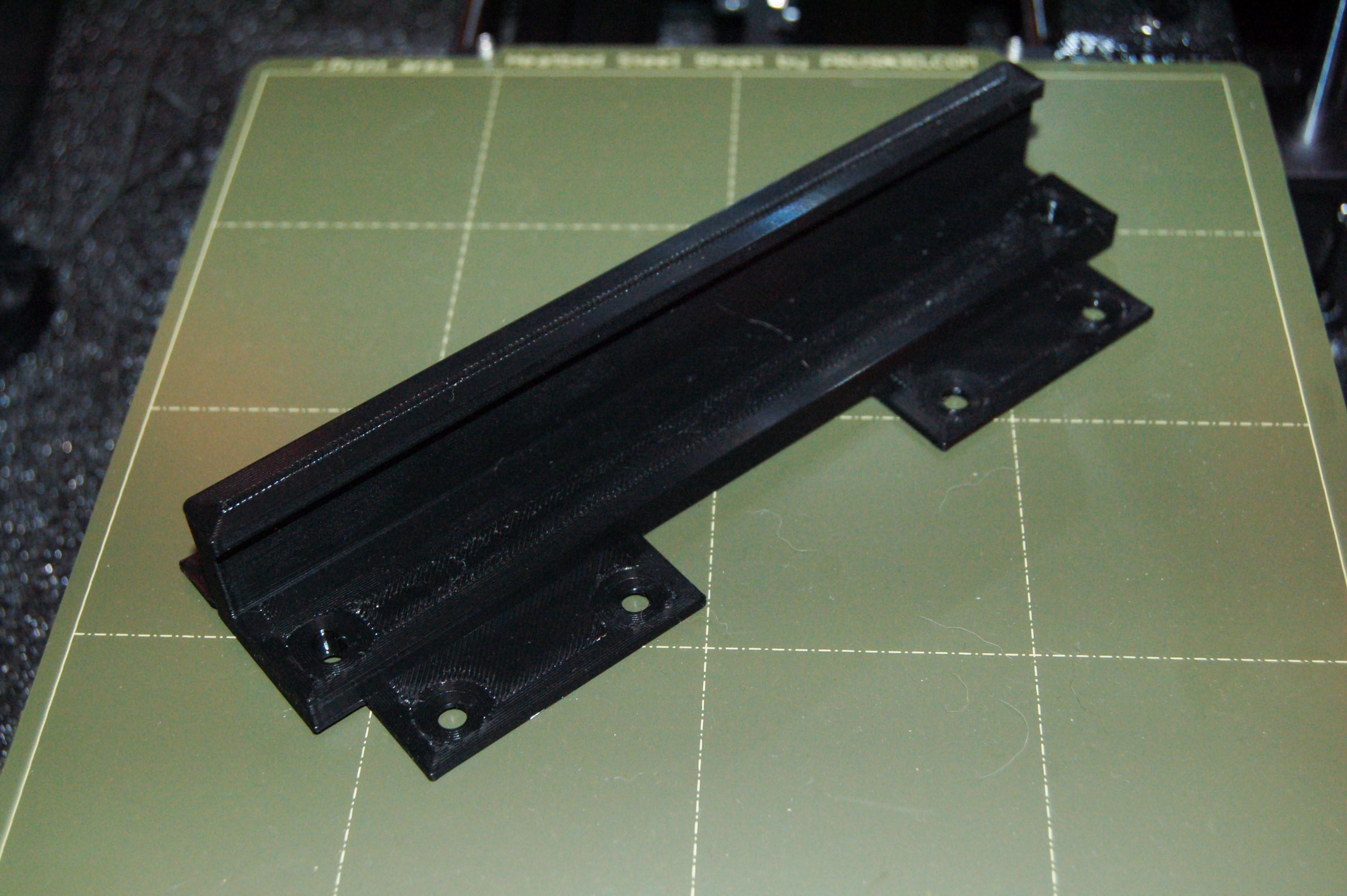
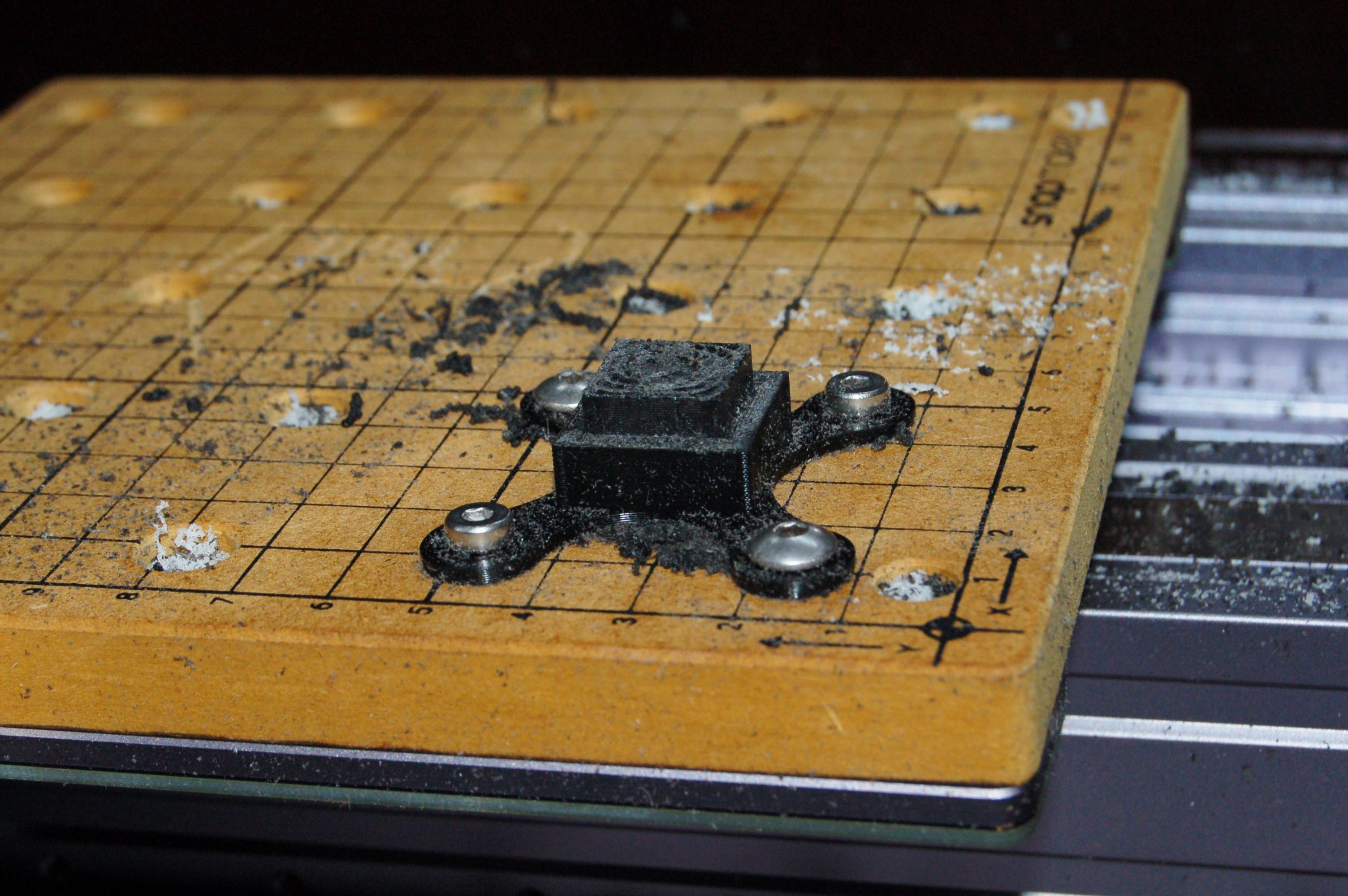
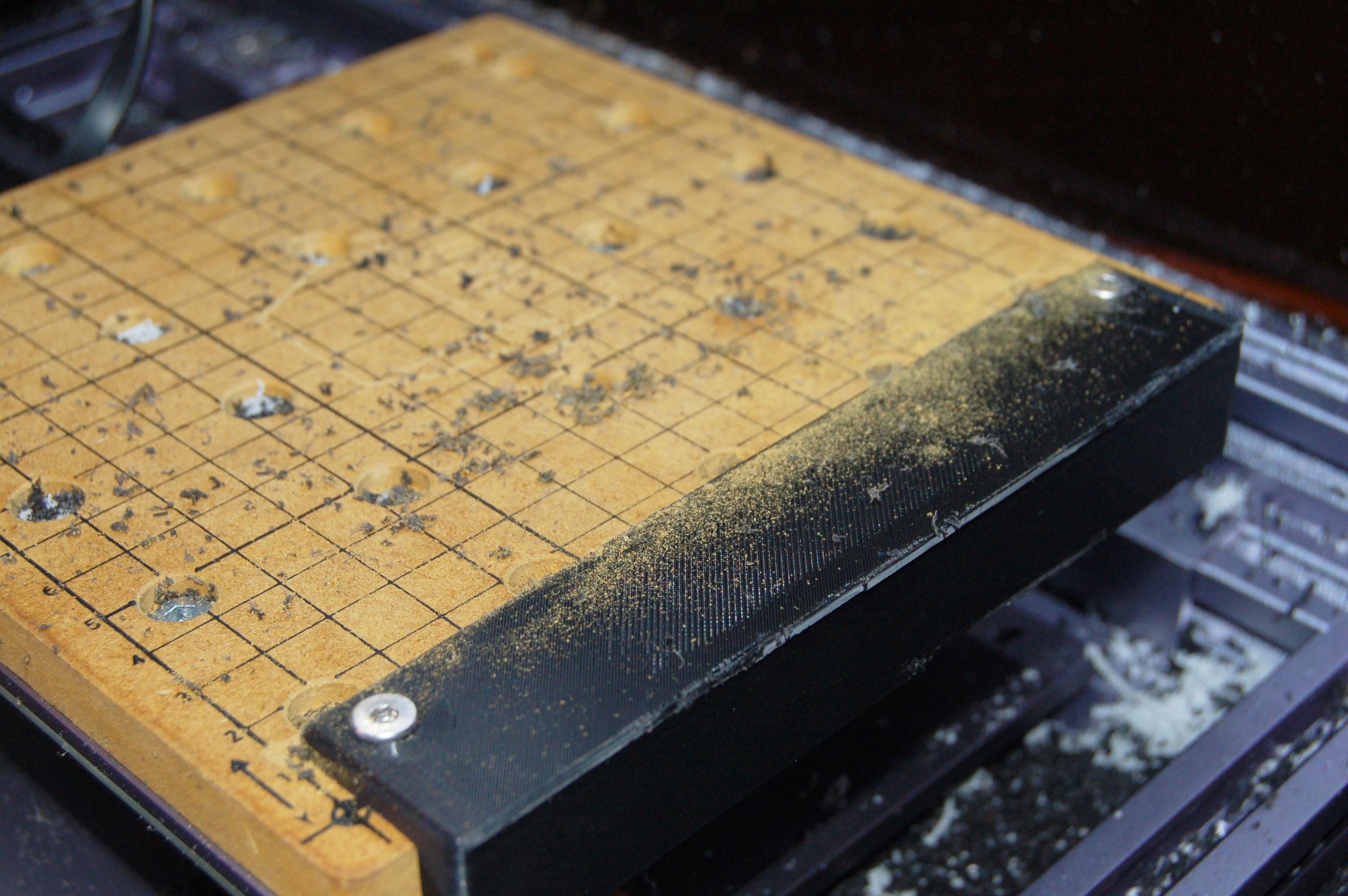
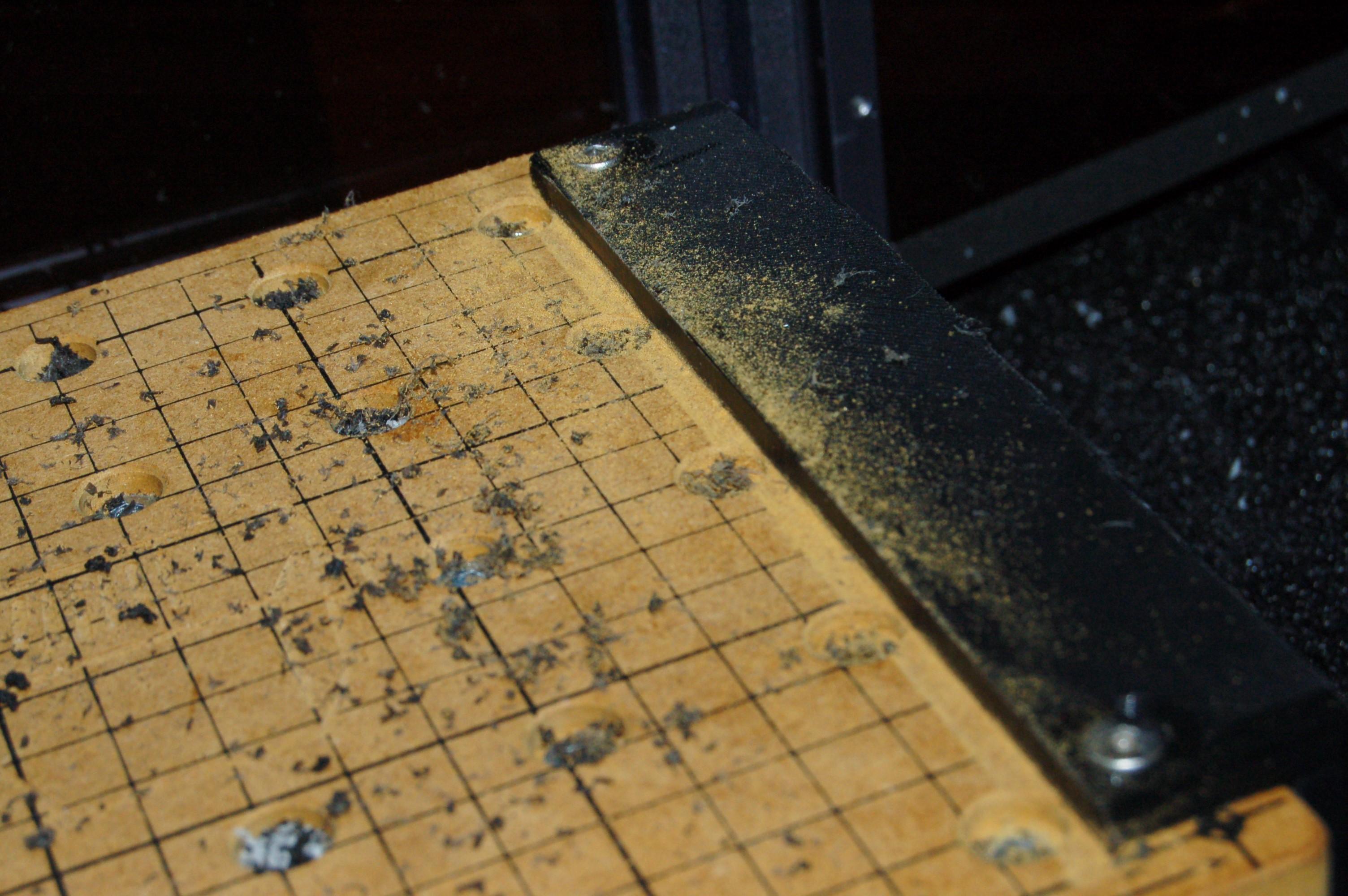
I then printed the edge part which can be seen in the images.
Machine the Square Edge

In order to perform the machining operations on the part, Fusion needs to know the shape of the part before and after the machining operation.
There are a couple of ways to produce the model of the 'stock' part before machining and 'final part' after machining. First is to simply model both objects in the design workspace. You can also make a 'Manufacturing model' in the manufacturing workspace (from the top toolbar) which allows you to make derivatives of your existing objects and modify them to either 'build up' to a stock part or 'cut away' to a final part.
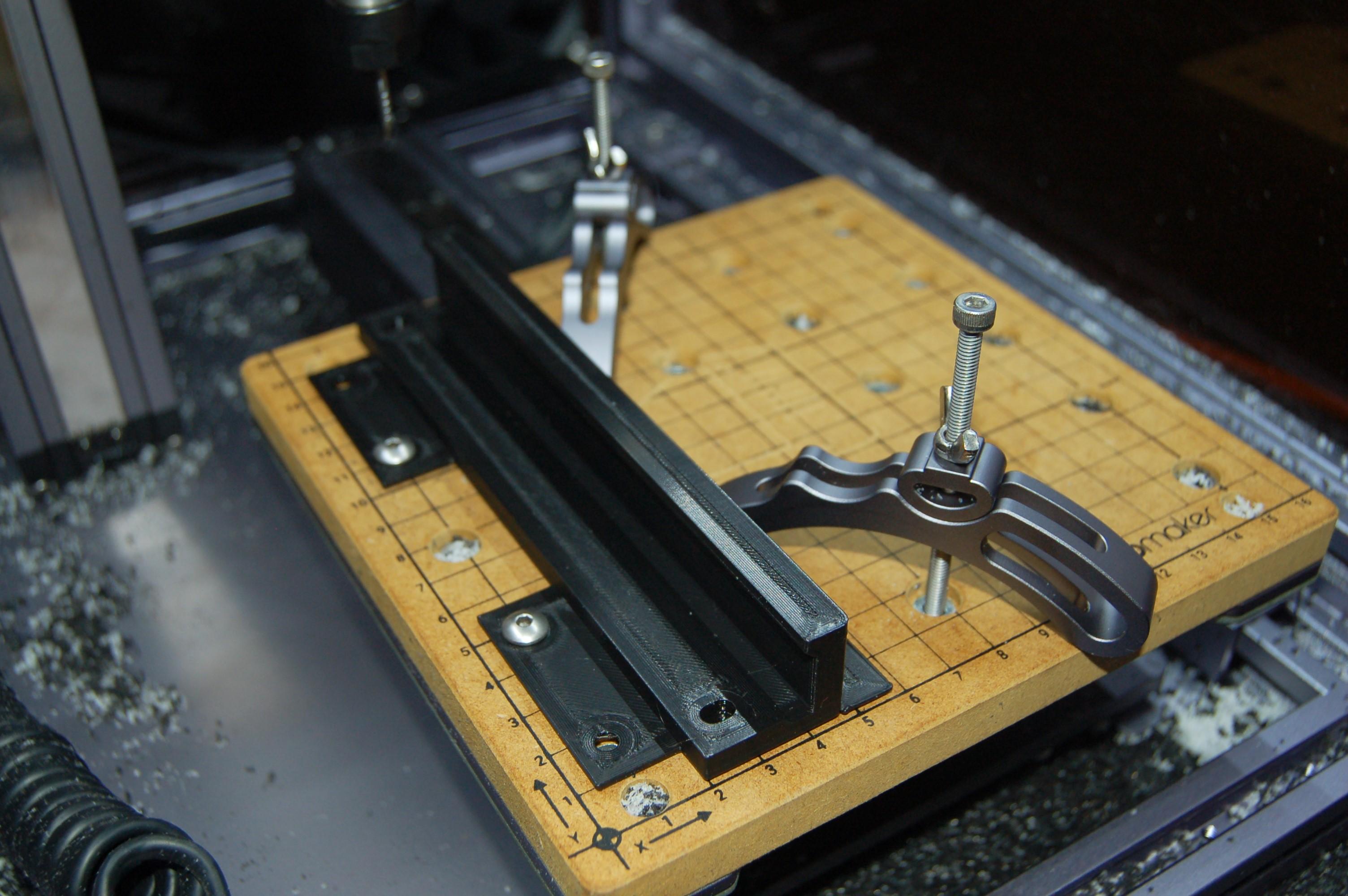
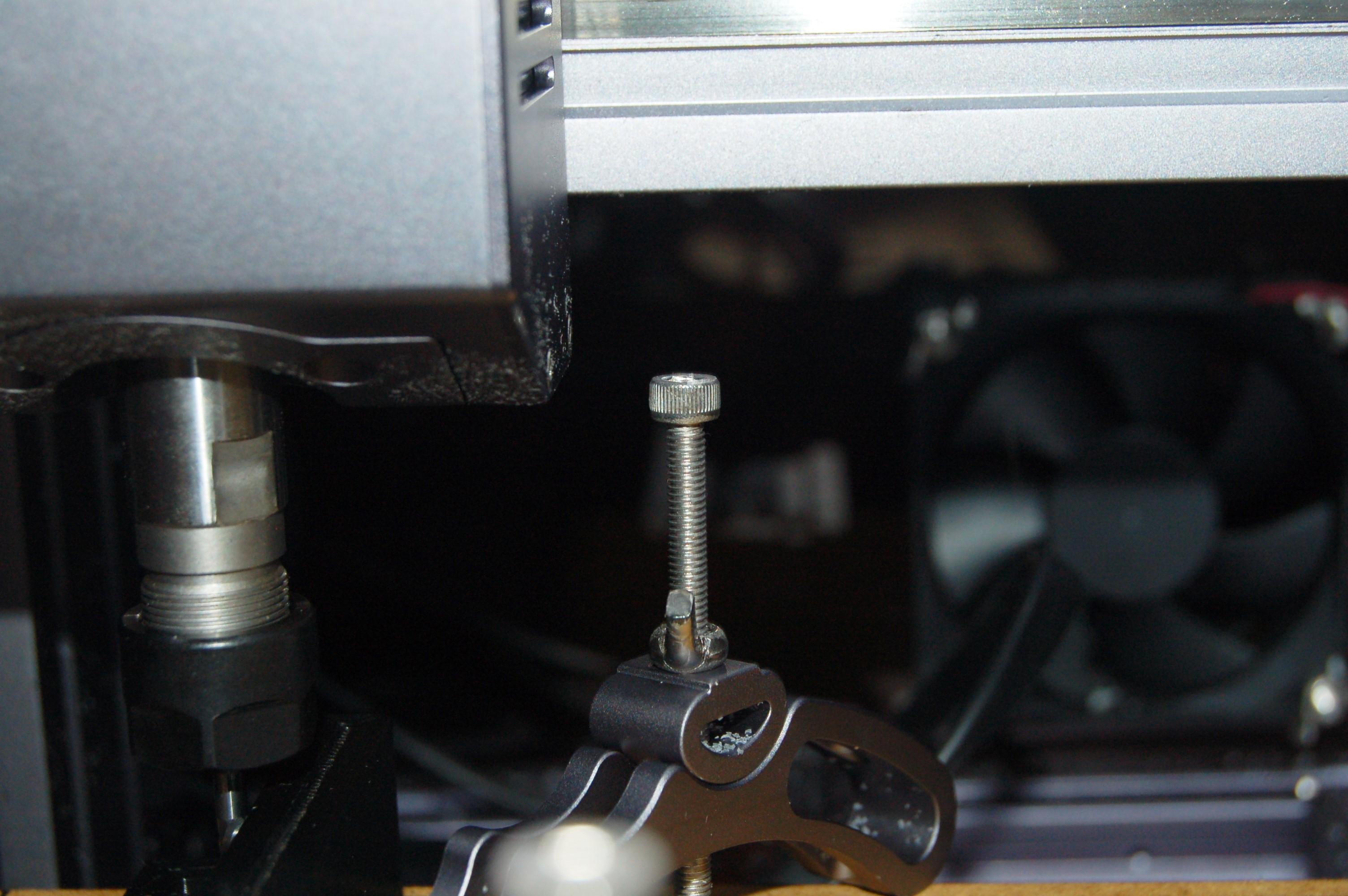
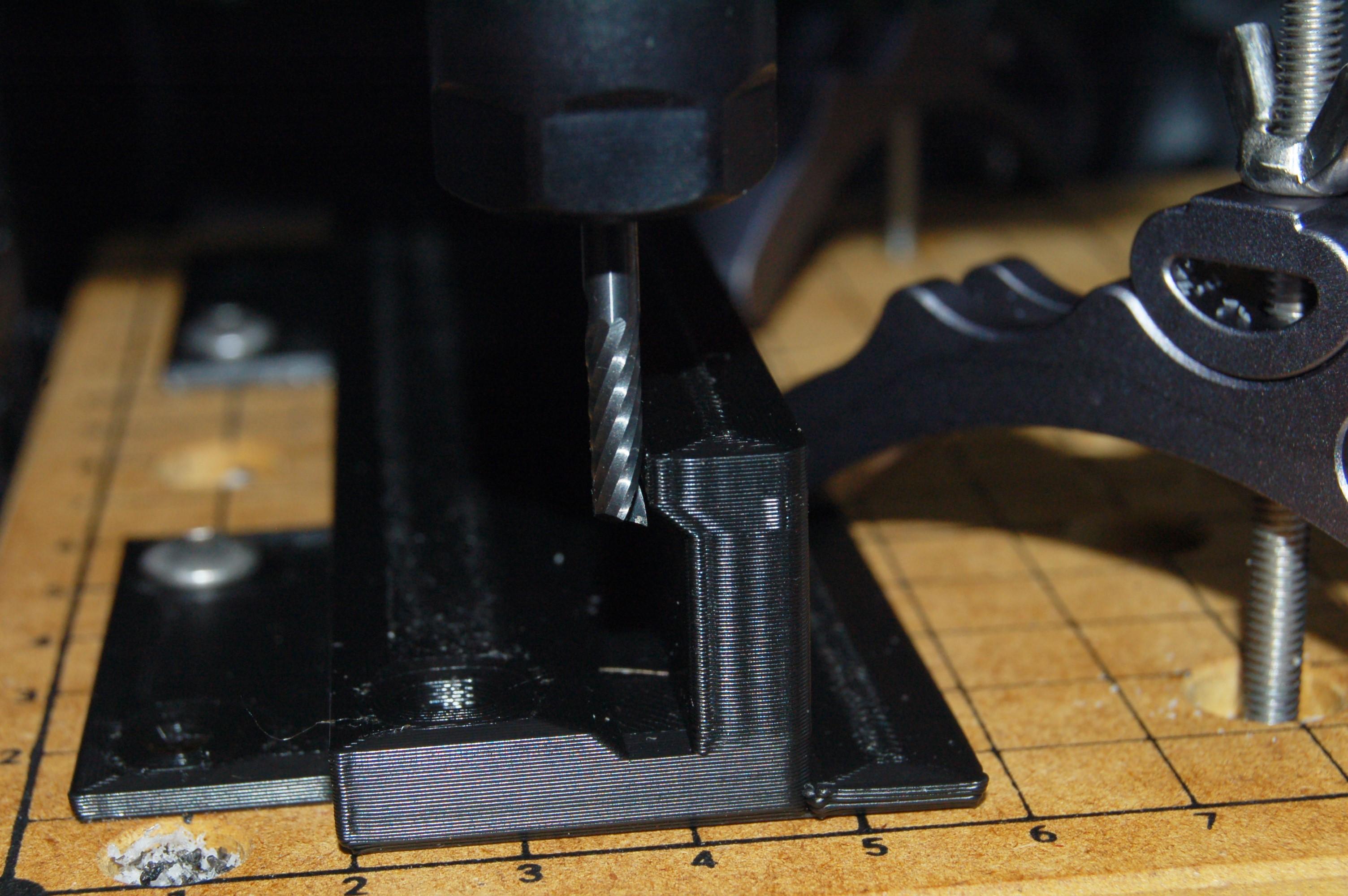
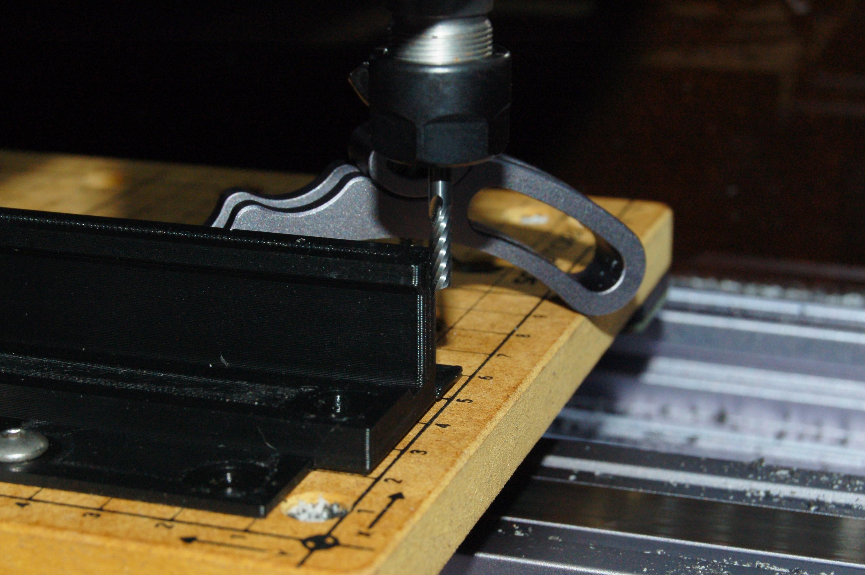
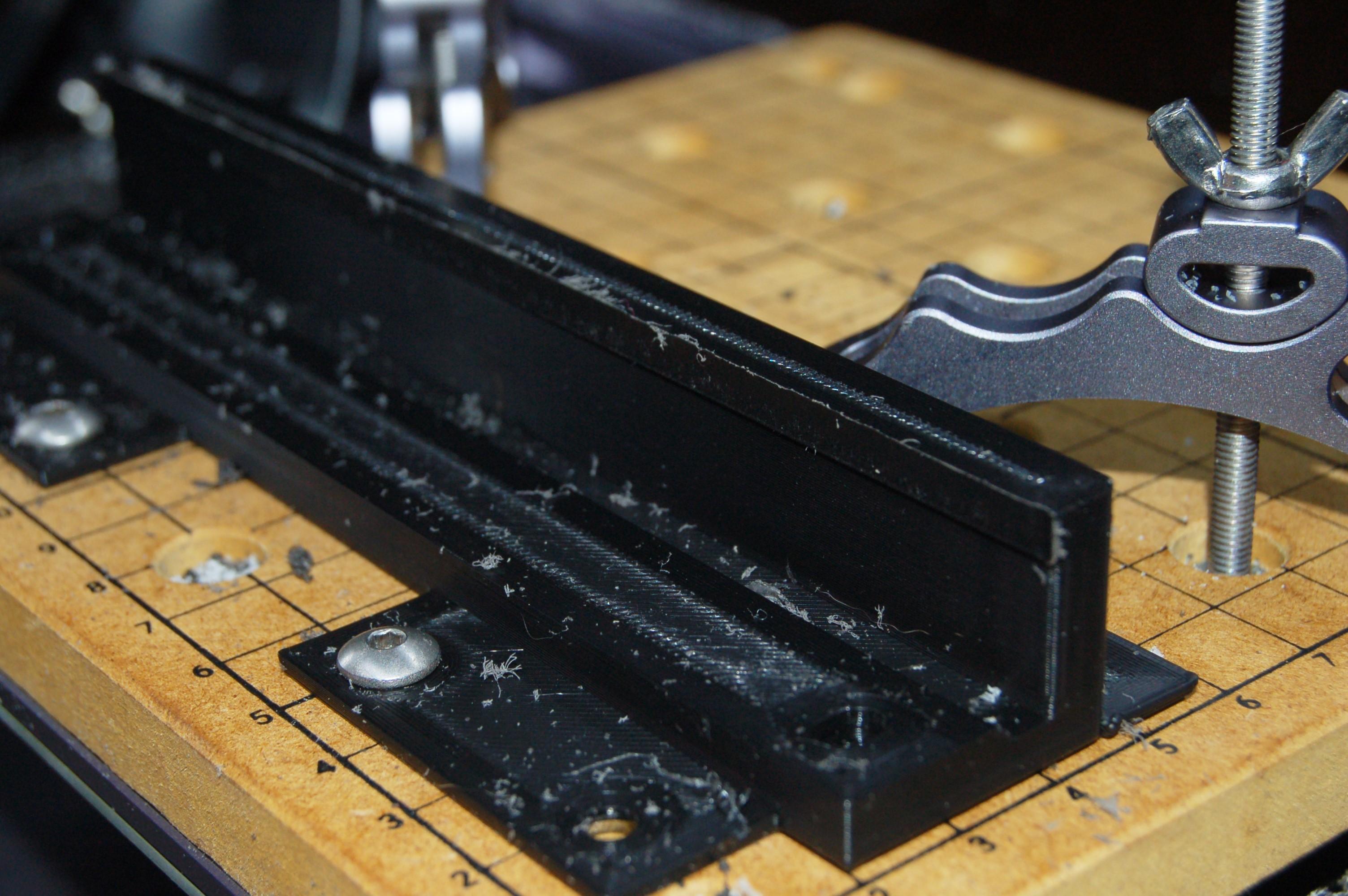
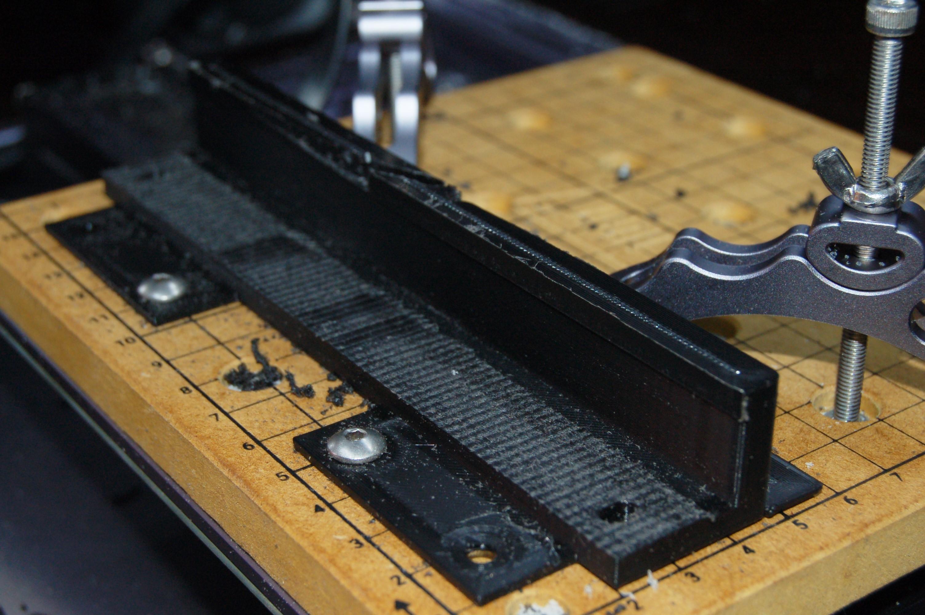
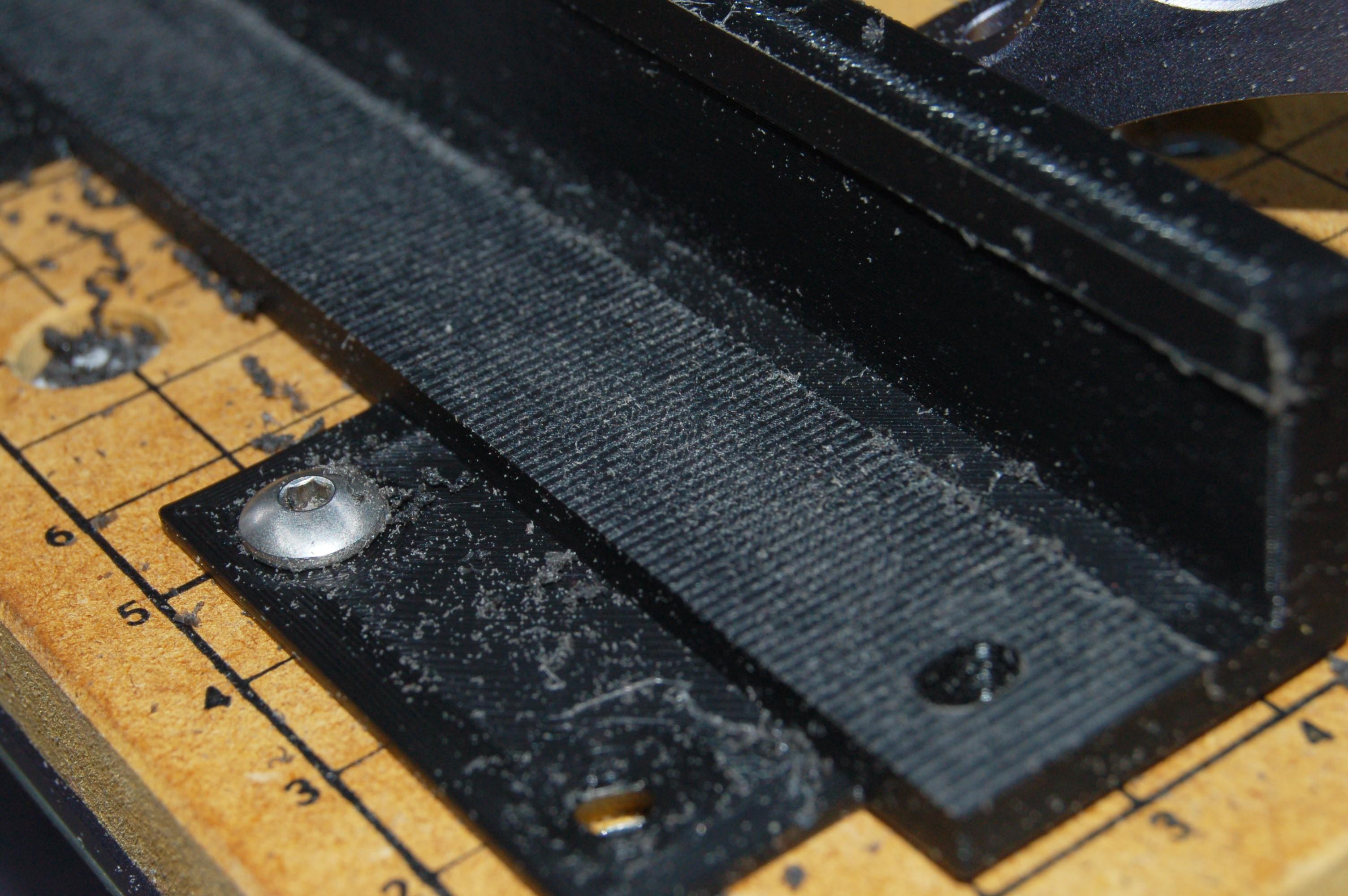
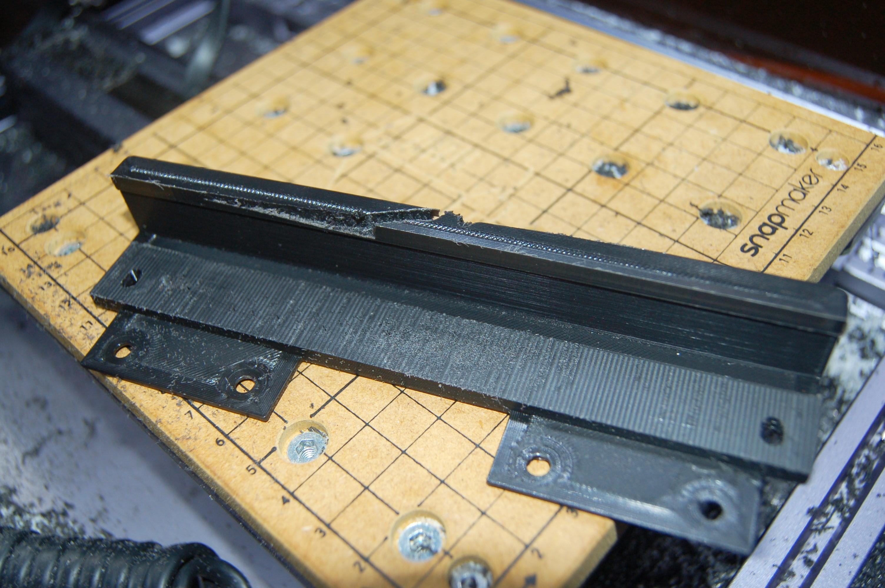
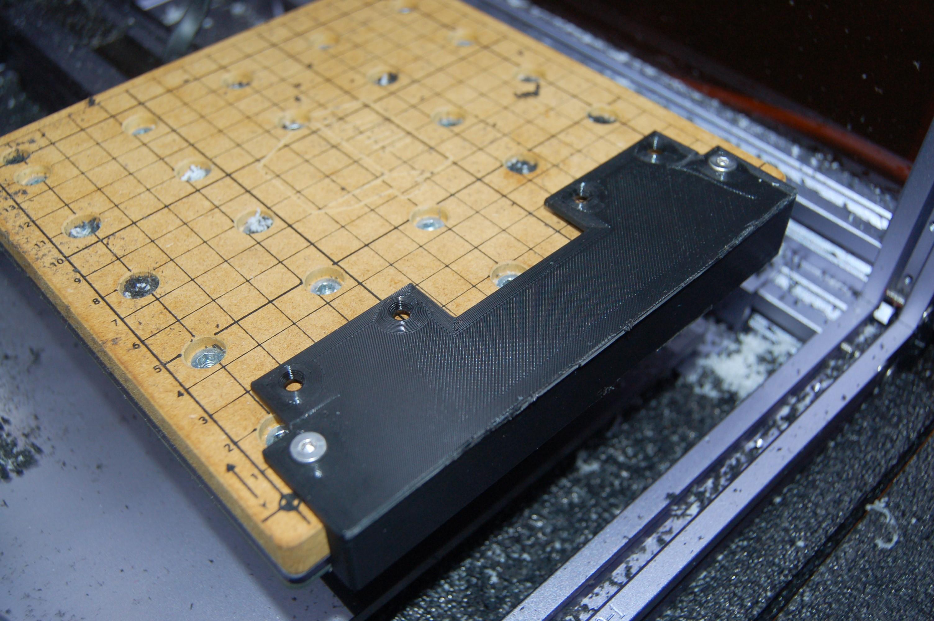
I designed the stock of the square edge with extra tabs to screw down onto the bed on one side, and clamp down on the other. Since the part was warped at the ends, I only clamped it in the middle, since if the part is deformed while it is being machined, the machined surfaces will go out of shape as it 'springs back' when it is being unclamped.
Its worth noting that there are tooltips on most of the options which will tell you what they do.
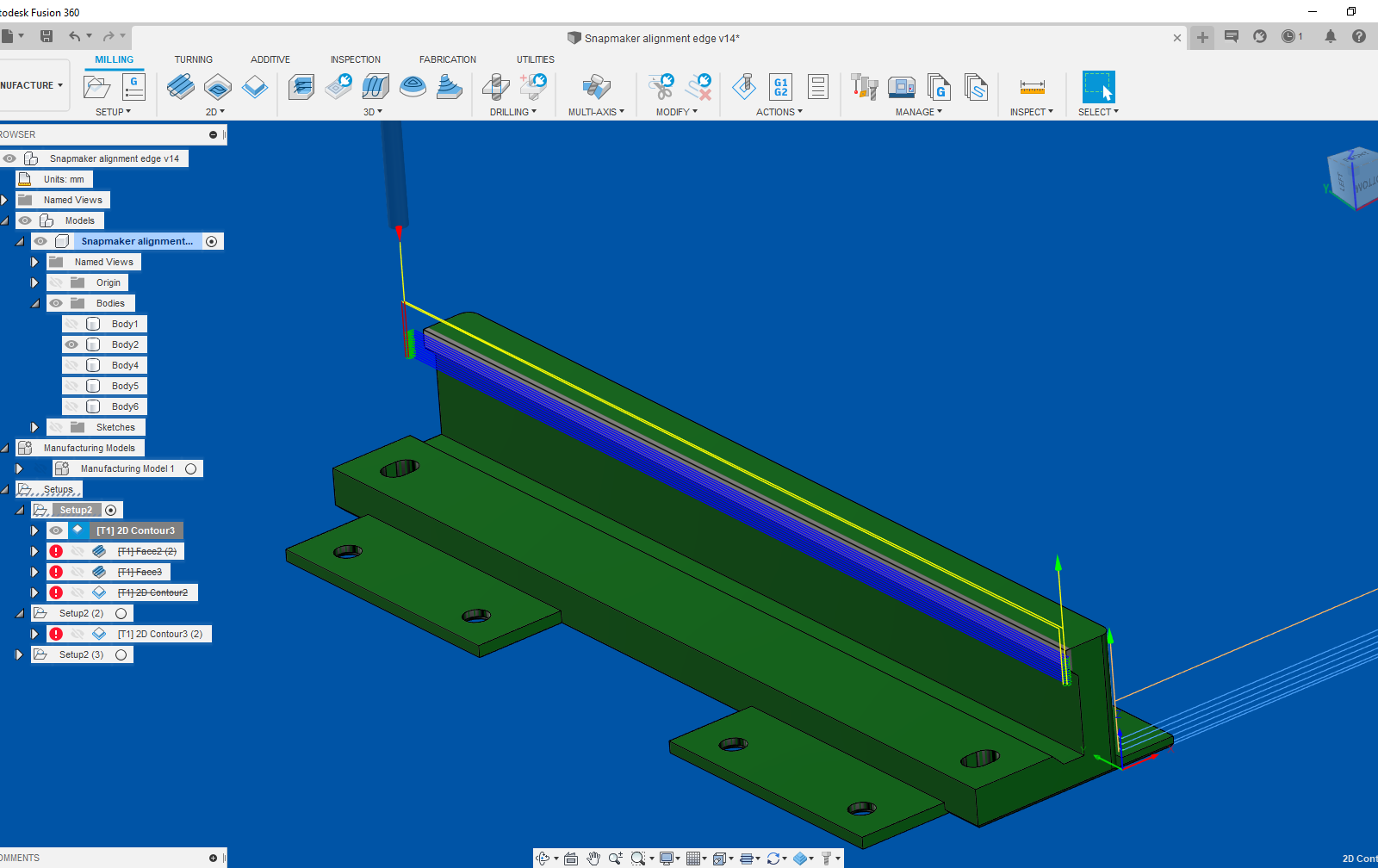
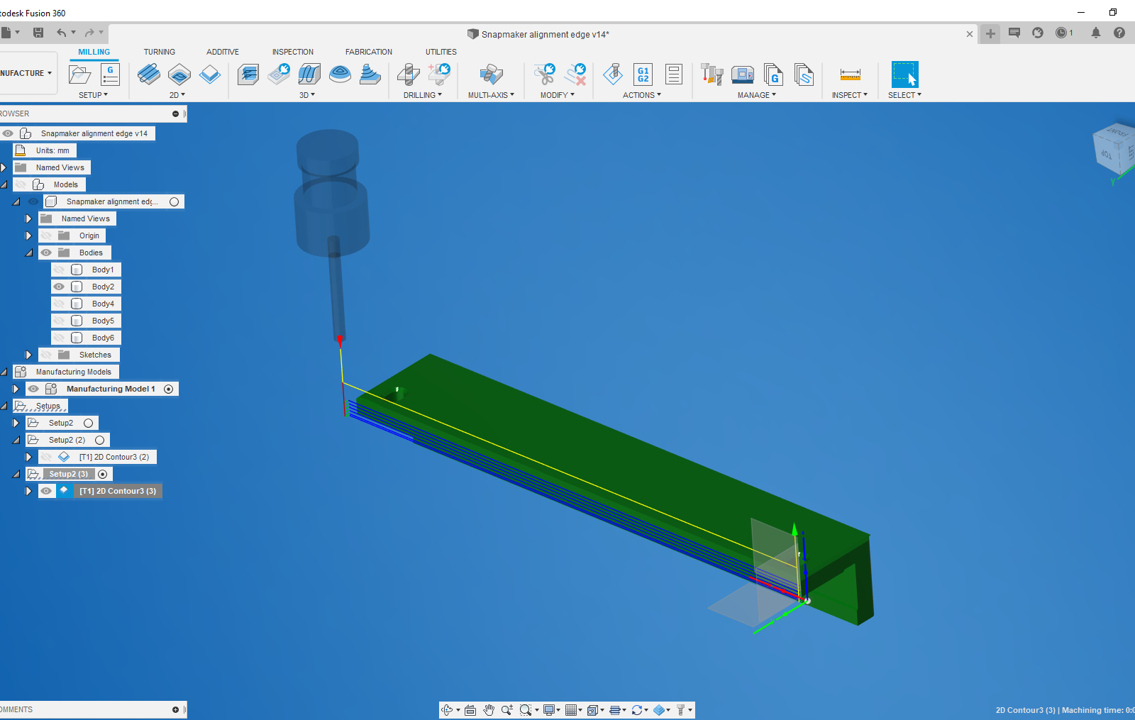
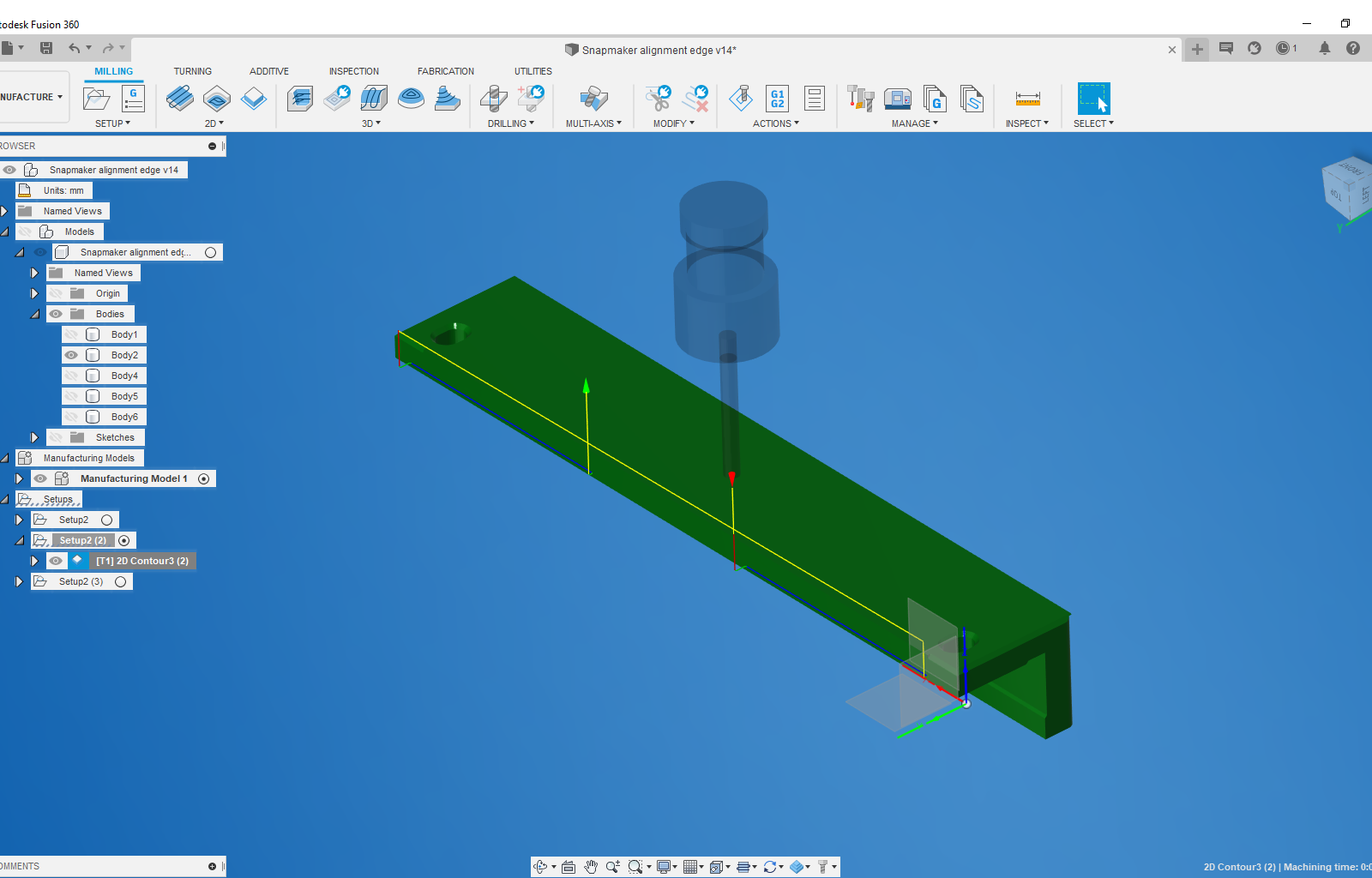
I used the manufacture workspace in fusion to do the machining operations on the edge part:
- Select setup on the top toolbar.
- This time select 'Milling' for the operation type.
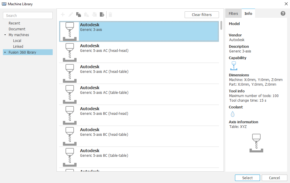
- You will again need to select a machine from the machine library, but this time it is a 'Milling' machine (click the checkbox on the right hand side in the fusion library). As in my case the Snapmaker was not in the library so I had to configure a new machine.
- Select 'Generic 3 axis' from the list (or however many axis your machine has) and copy it into your local library.
- Click the small pen icon to configure the machine e.g. work envelope, maximum feed speeds, coolant etc. Once you are happy with the machine configuration, select it and click the 'select' button in the bottom right.
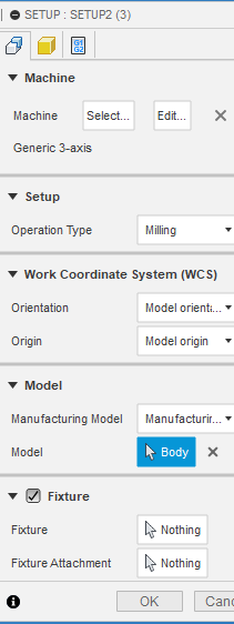
- You will need to set the orientation and origin for the workpiece using the options provided. The origin location is important, and it is best to make it a location on the part which is easy to reference e.g. a square corner.
- The model subsection is to select the body which represents the shape of the part after machining.
- In the fixture subsection you can select the models of any fixtures on the design e.g. hold down clamps, screws. This way fusion can avoid colliding into them when generating the toolpath.
- Click the 'Stock' tab on the setup dialog window (the yellow cube) and select the body which represents the object before machining i.e. the stock the part will be machined from. Ussually the stock is a square block of solid material, in this case the stock is the specific part I 3D printed, so select that.
- Click 'Ok' for the setup.
Now we want to do the processes which remove material from the part. In this case, simple 2D contour and facing processes are needed. Select 2D contour:
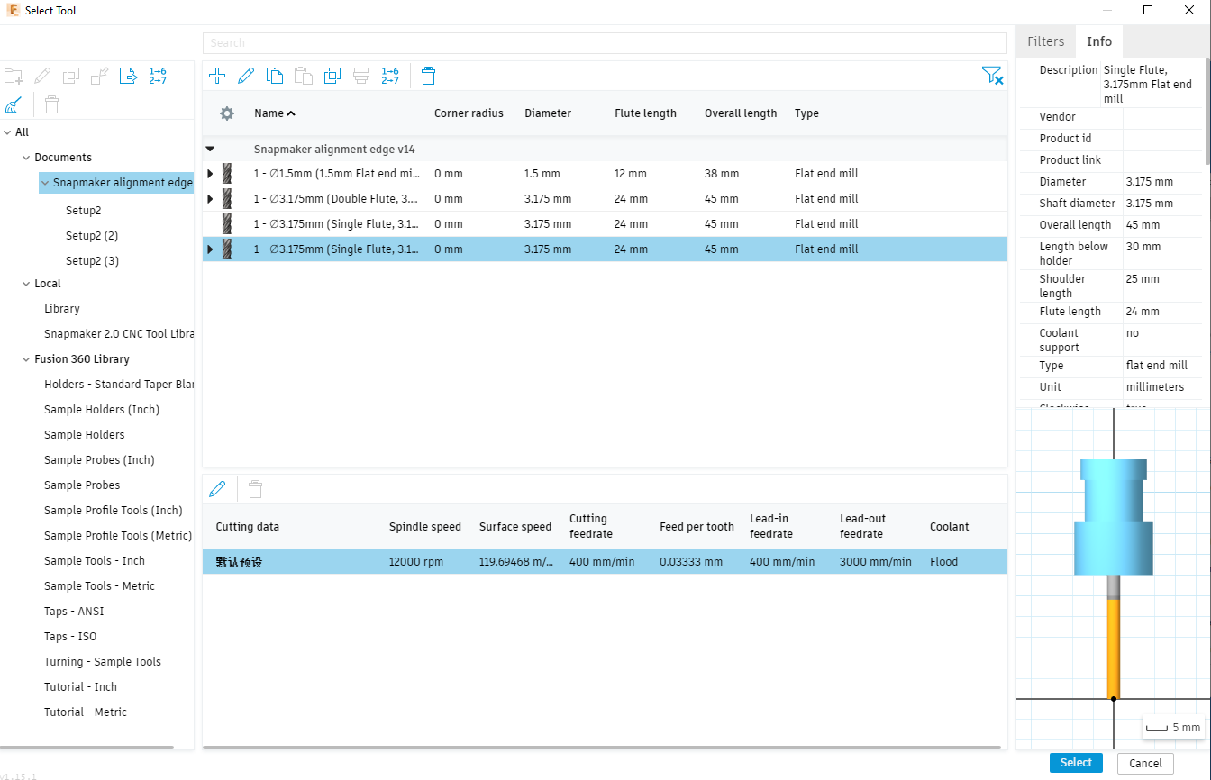
- Firstly, we want to 'Select' the tool we are using, so click on that.
- This will open the tool library. In the case of the Snapmaker the tool library was imported (instructions on the Snapmaker website). If your tool is not already in the library, you will need to configure a new one.
- Set the coolant as necessary (disabled if you don't have any).
- For the feeds and speeds section, the important setting to set are the spindle speed and cutting feedrate. These particular settings will depend on the material you are cutting and the tool you are using. A general guide is to make sure the 'chip load' or 'feed per tooth' is appropriate for the material you are cutting (lots of good info on this online). It's good to do some test objects beforehand to find some good settings for the material. If plastic is cut too slowly for example, it will melt instead of cut and produce a very poor finish. For this contour I used a feedrate of 1200mm/s (quite high) and with the standard Snapmaker 3mm single flute cutter and a spindle speed of 12000 rpm (this is fixed on the snapmaker and cannot be altered).
- In the geometry tab (and geometry subsection), select the geometry of the final edge you want to cut to.
- In the stock contours subsection, select the 2D boundry of the geometry you want to cut from.
- In the heights tab, you select the various heights to machine from and to. Its important to set the clearance height above the part and any clamps in the workspace. This is the height the machining process will start and finish at. I found out at my own expense that if the clearance height is not above the part when it finishes, the snapmaker descides to return to the X-Y home position and promptly drove through the side of my nicely machined part :(.
- In the the 'Passes' tab the most important settings are 'Stepover' and 'Stepdown'. 'Stepover' is basically how much material is removed sideways during each pass while 'Stepdown' is how much is removed downwards with each pass. If you want more than one stepover or stepdown with each pass, you will need to check the 'Roughing passes' and 'Multiple depths' boxes respectively. I used a stepover of 0.5mm and stepdown of 0.4mm. This is quite low for cutting plastic but I kept it conservative since the Snapmaker motor is not too powerful (50W) and the A150 frame is not that rigid.
- In the linking tab you can alter settings on how the tool moves between cutting passes.
Once you click ok, it should generate the toolpath or throw an error that needs to be addressed.
Again the the toolpath needs to be postprocessed for your particular machine (in this case the snapmaker postprocessor which can be downloaded from their website) and then the file saved.
When setting up the CNC file before running, you will need to set the origin for the part on the machine before running the file. The origin needs to be set in the same place you set the work origin in the setup above. The best option is to set it at the corner of the stock. This way you can use a calibration card to just touch the side of the stock with the tool, account for the tool width and then set the origin in the particular axis (and repeat for the other side of the corner). It can also be beneficial to set the Z origin at the surface of the work platform. Do a quick check by doing a work boundary sweep to make sure it won't collide into any clamps or parts, then start the file!
For the straight edge I also did a facing operation (similar settings to 2D contour) to flatten the base of the edge.
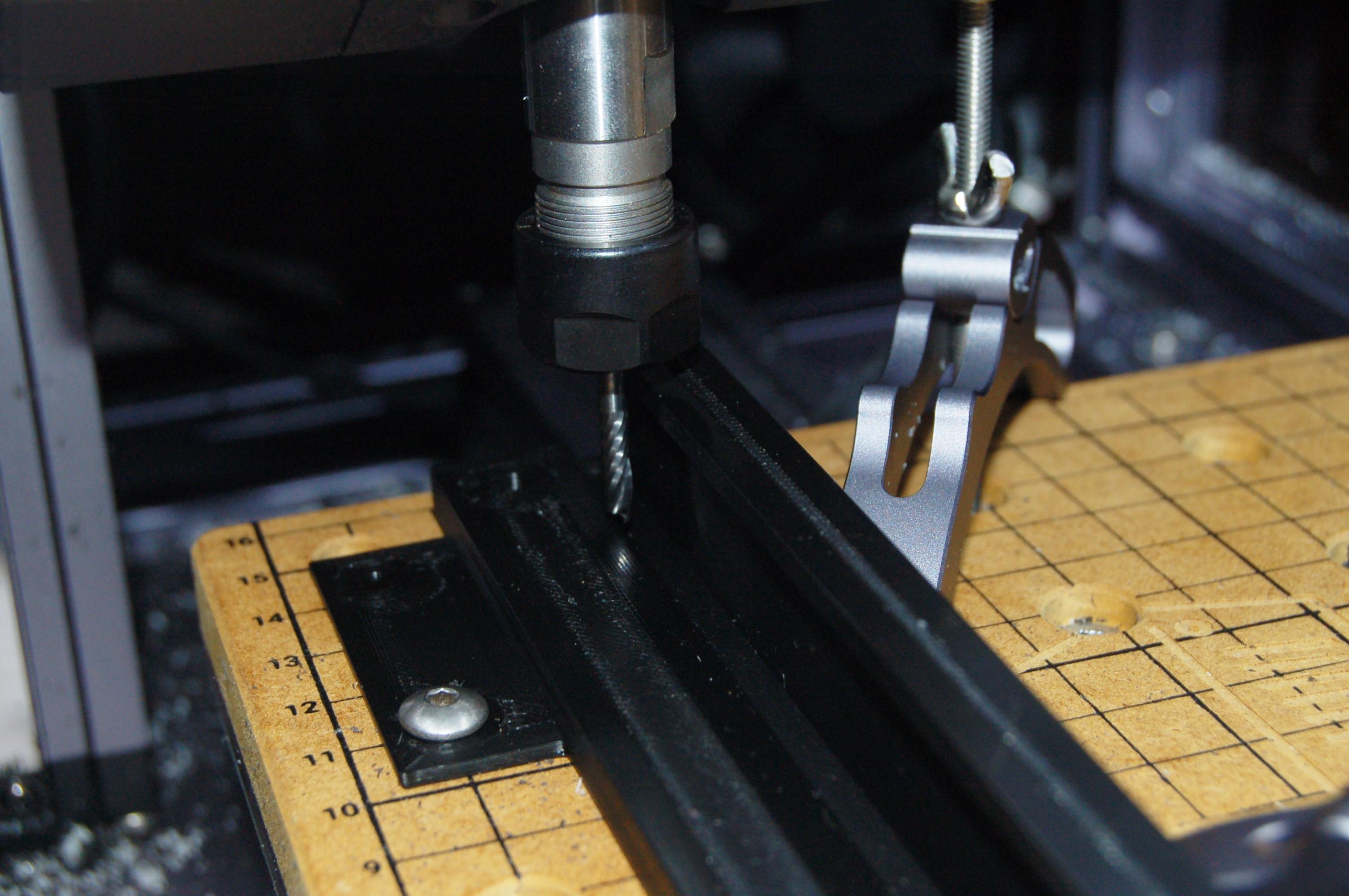
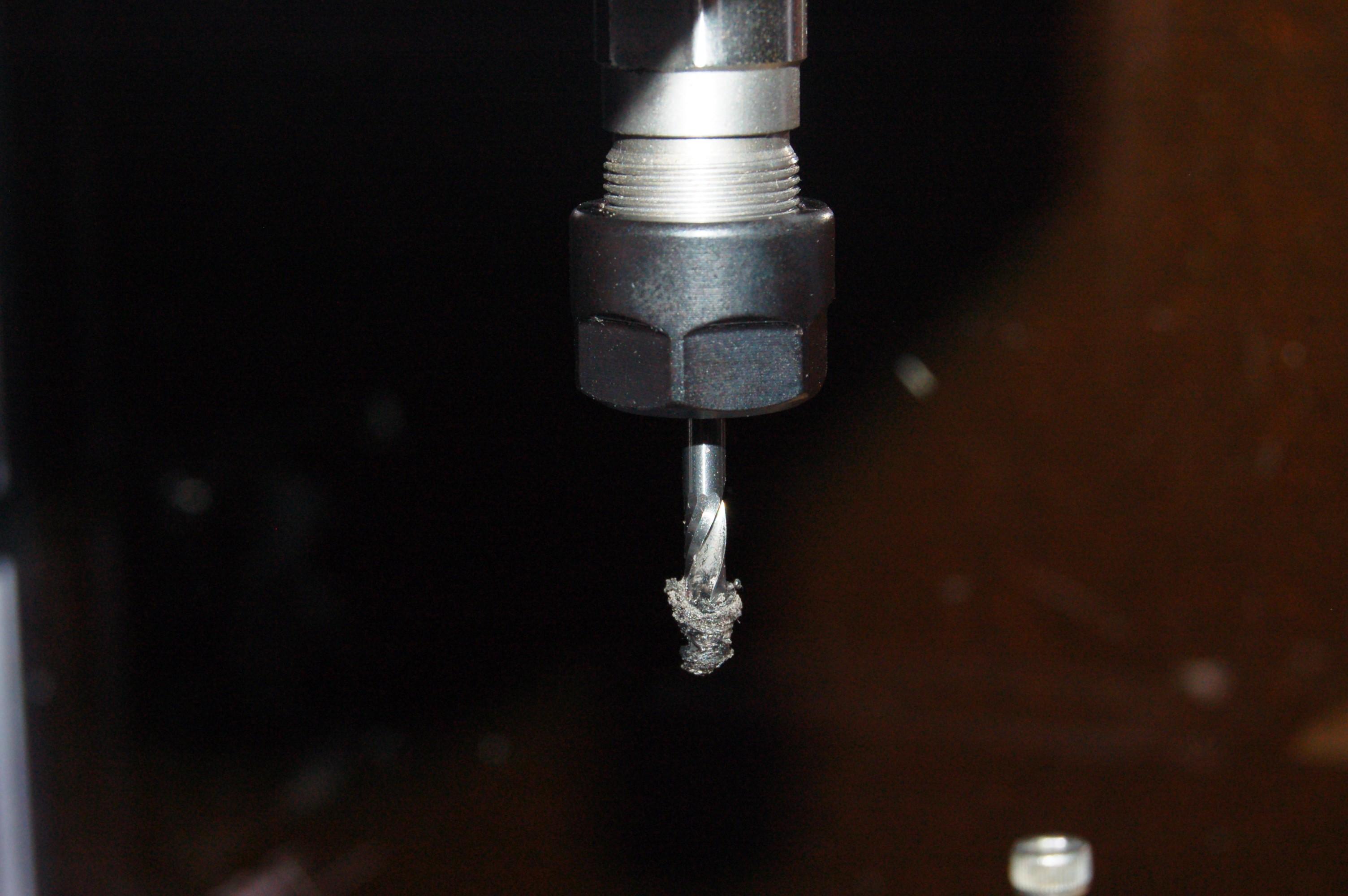
PLA is tricky to machine since its melting temperature is so low but it is also relatively hard. Occassionally plastic gets melted onto the bit and the process has to be paused to remove it. For cutting plastic, the best bits are single 'O Flute bits' which are optimised for removing chips as quickly as possible to stop them jamming up and melting against the tool. Fortunately, the stock bits which come with the Snapmaker are O flute, including some of those sold on their website.
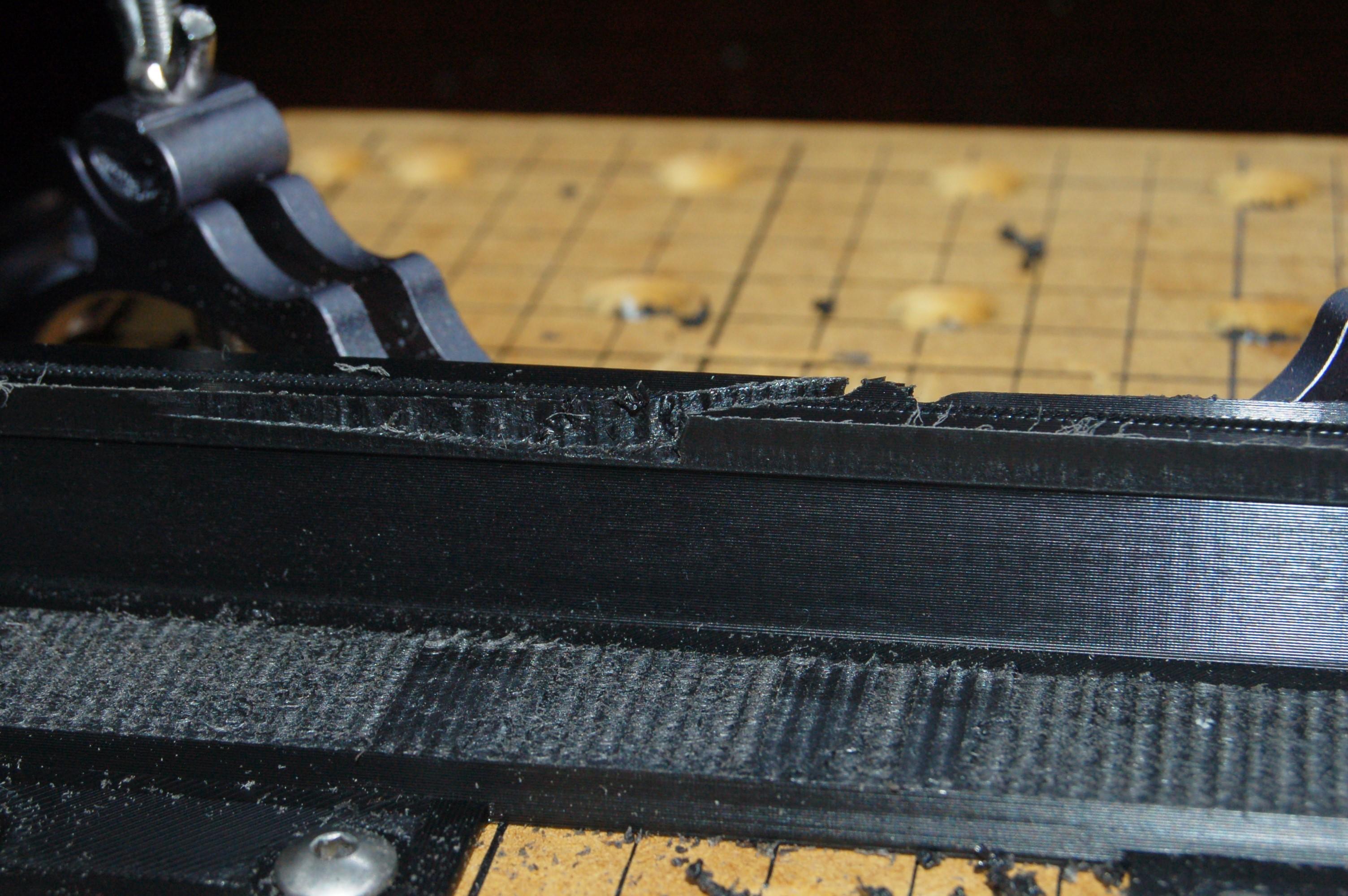
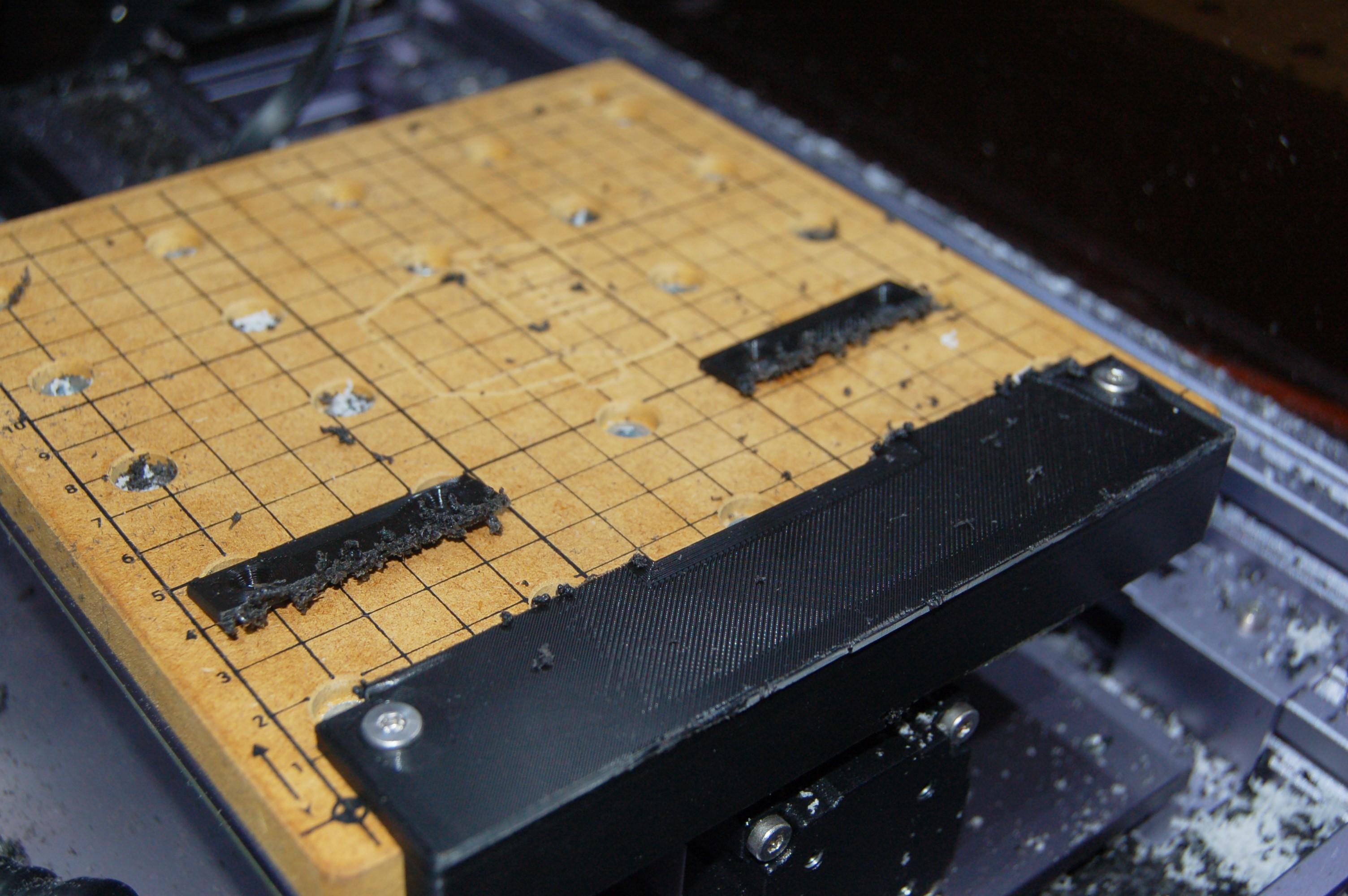
Once the inner side and base of the straight edge were machined to a good finish (for referencing against the side of and top of the workbed when reassembling) the final step to machine the edge was the clamp it in position on the work bed. A couple of quick passes were done to cut away the tabs, and then the edge was machined with a contour operation to its final straight edge. Since the straight edge is cut by the machine itself, any object placed against it will be square to the machine co ordinates.
Produce the Final Object
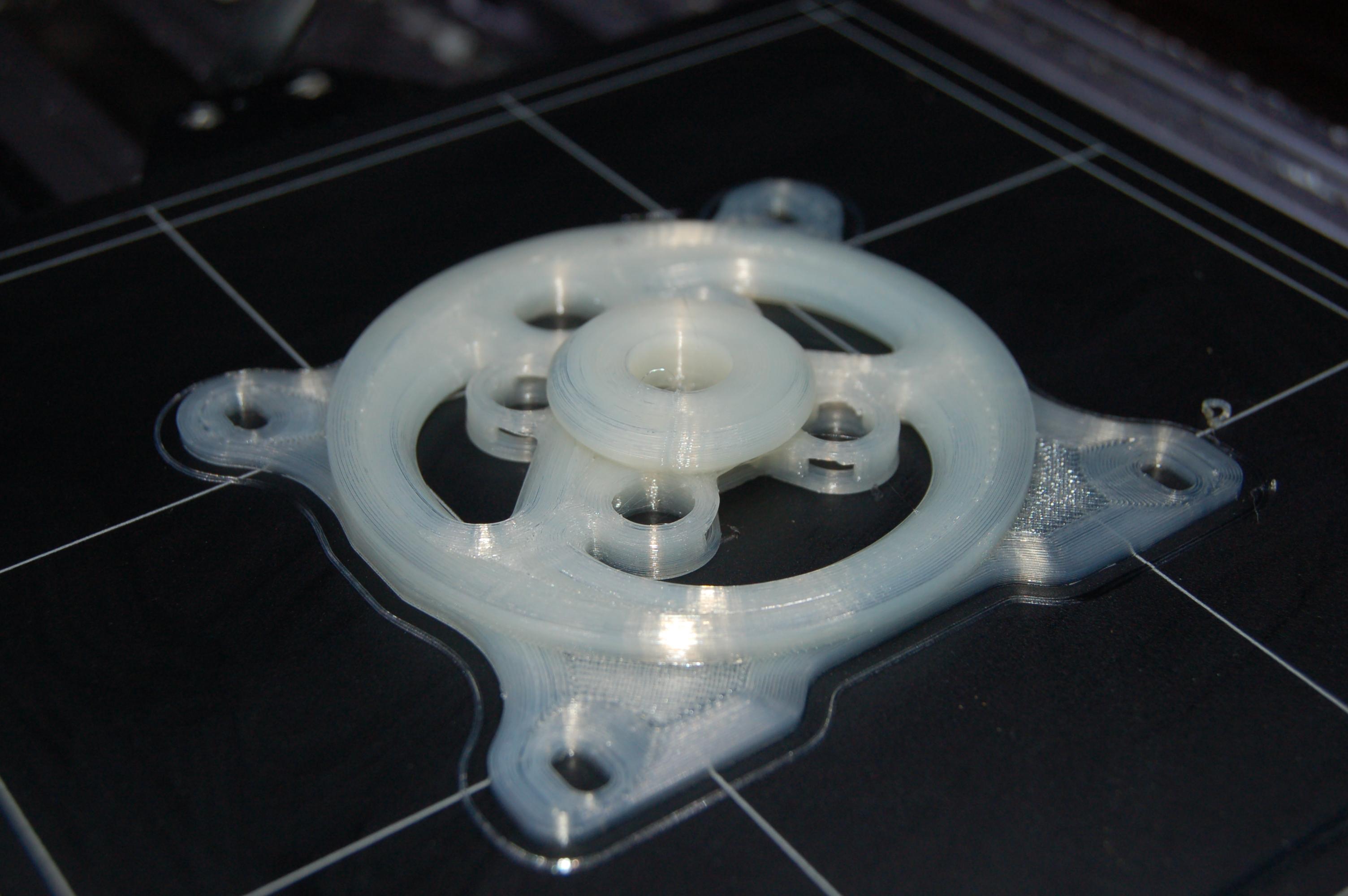
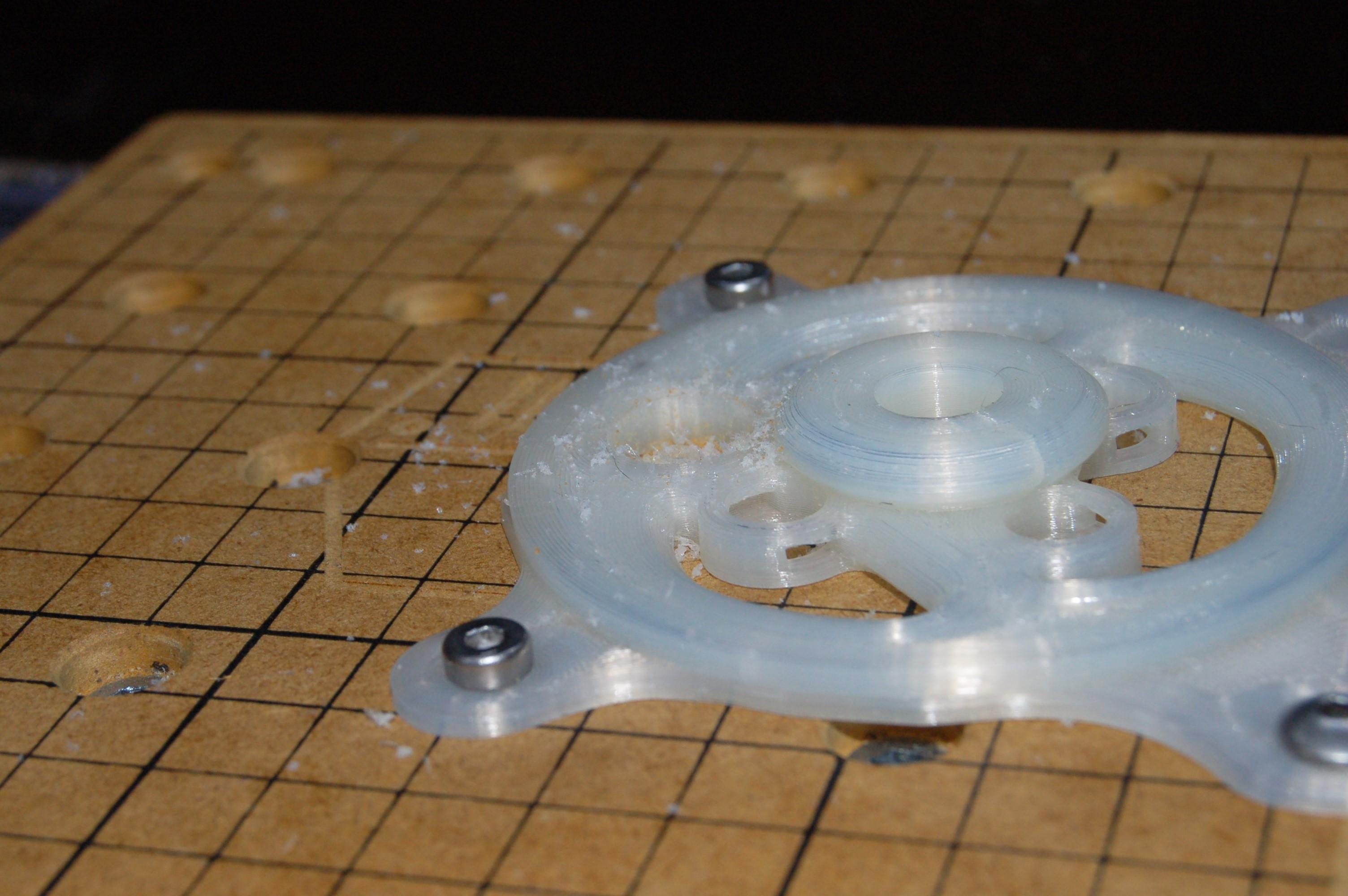
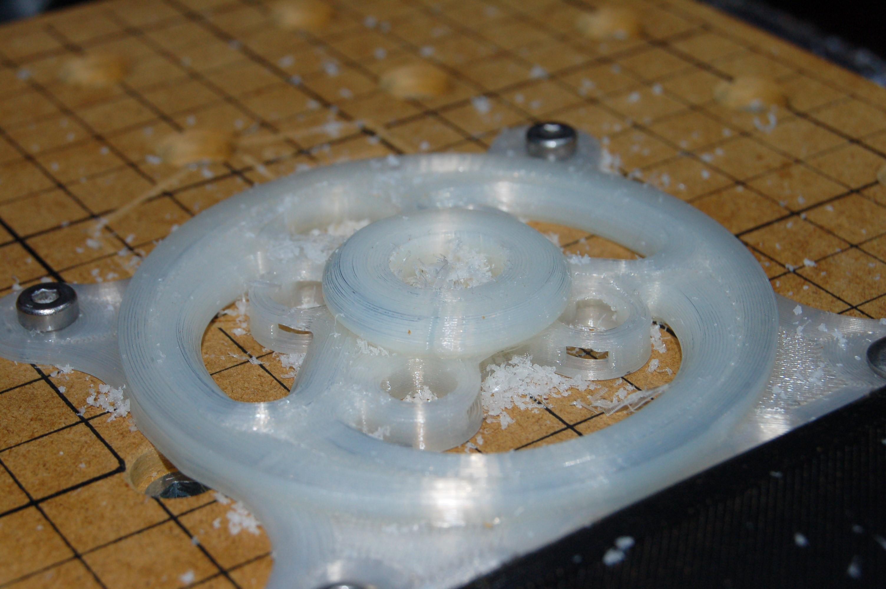
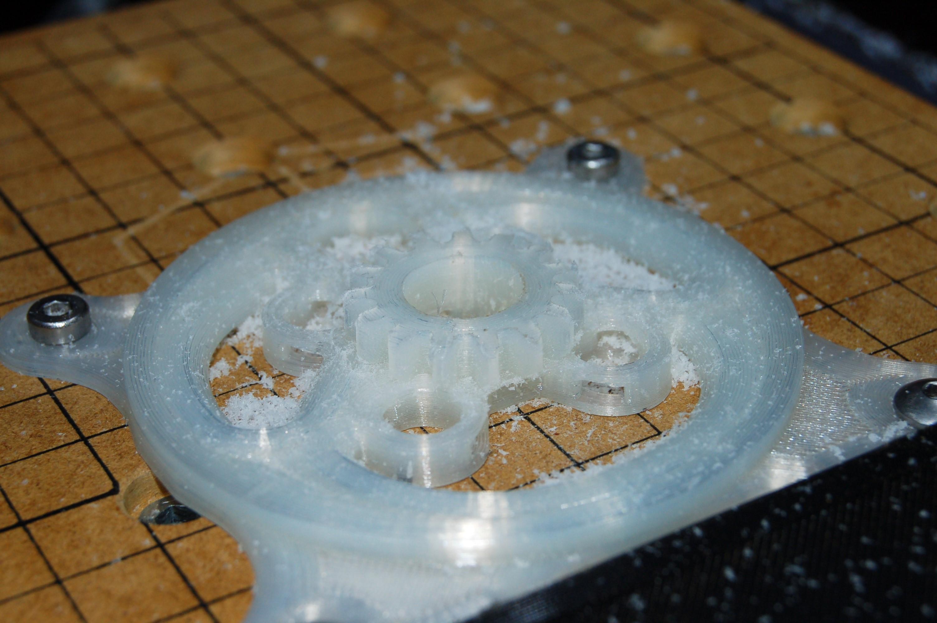
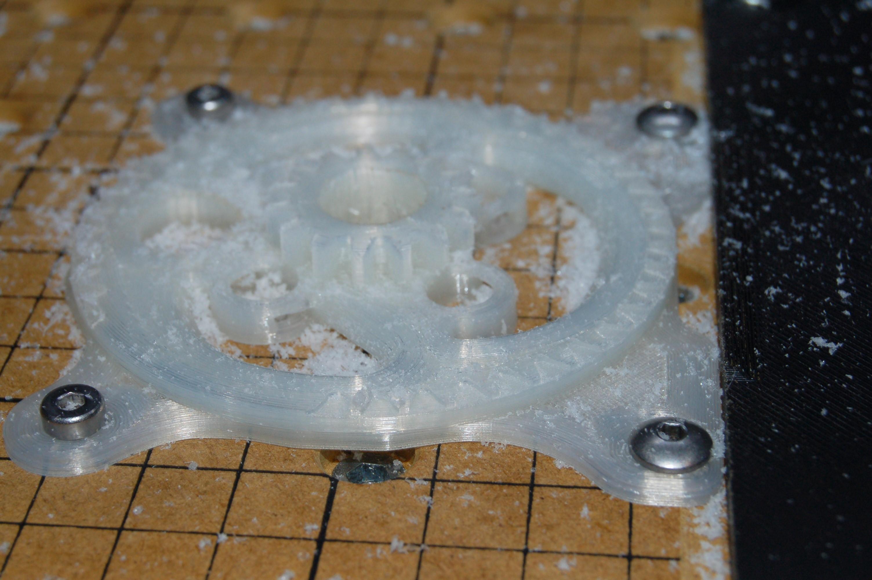
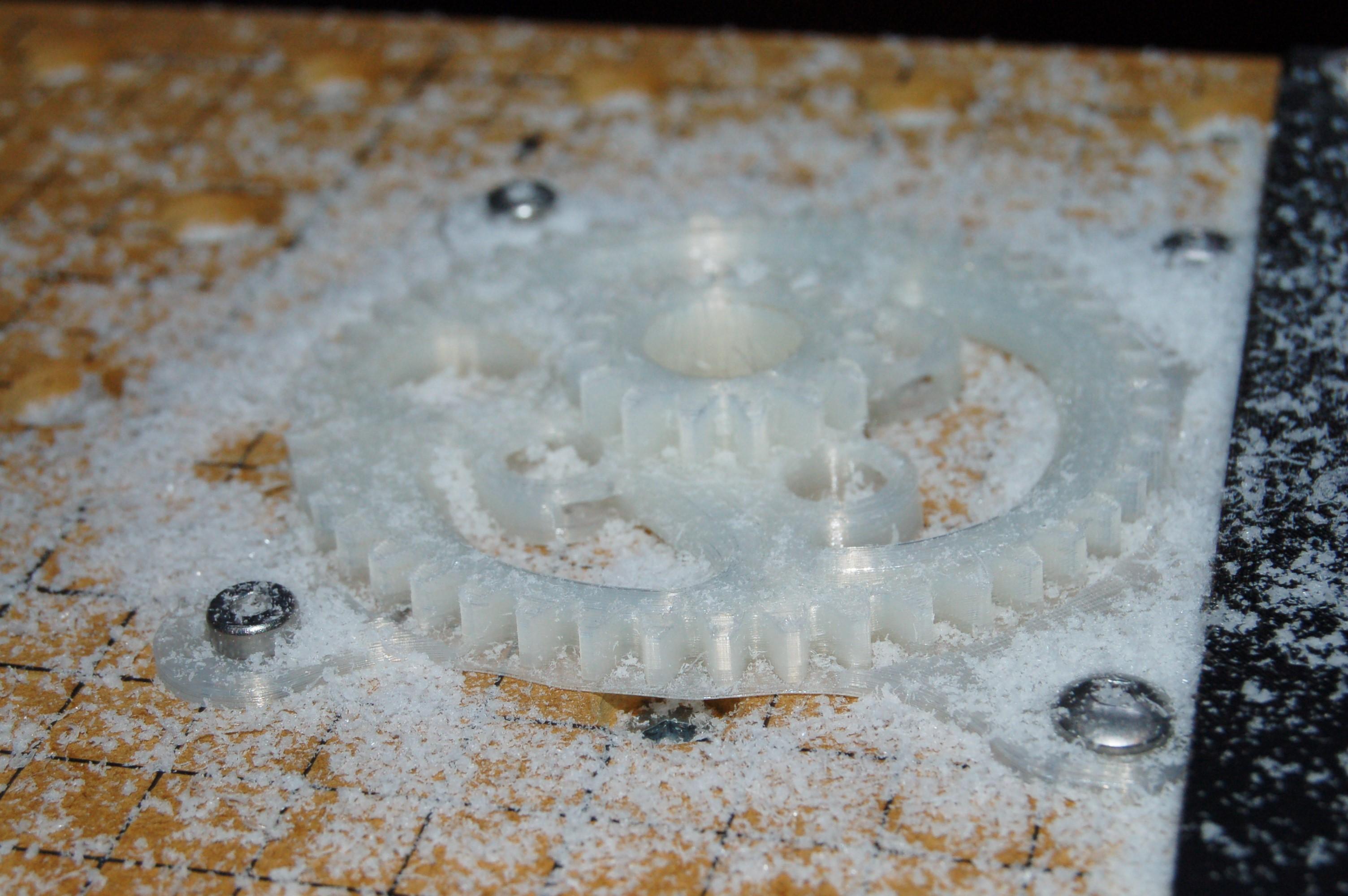
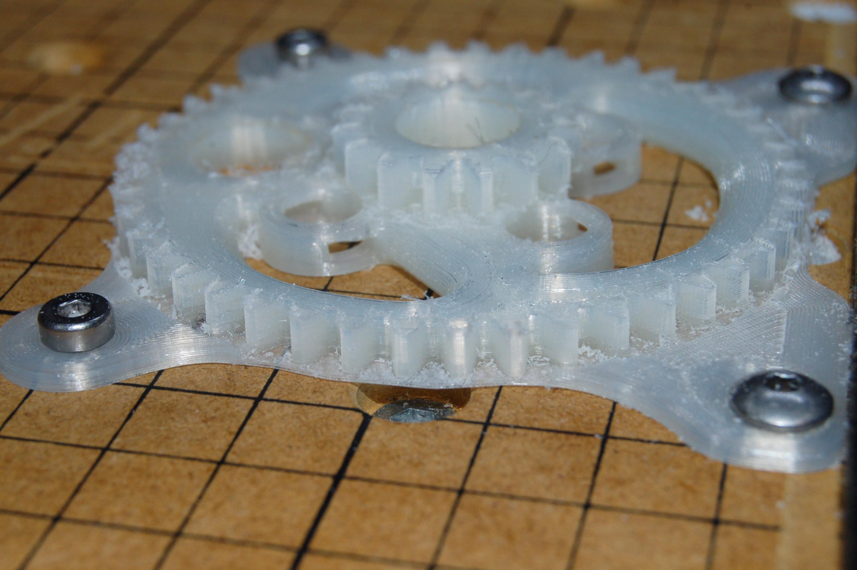
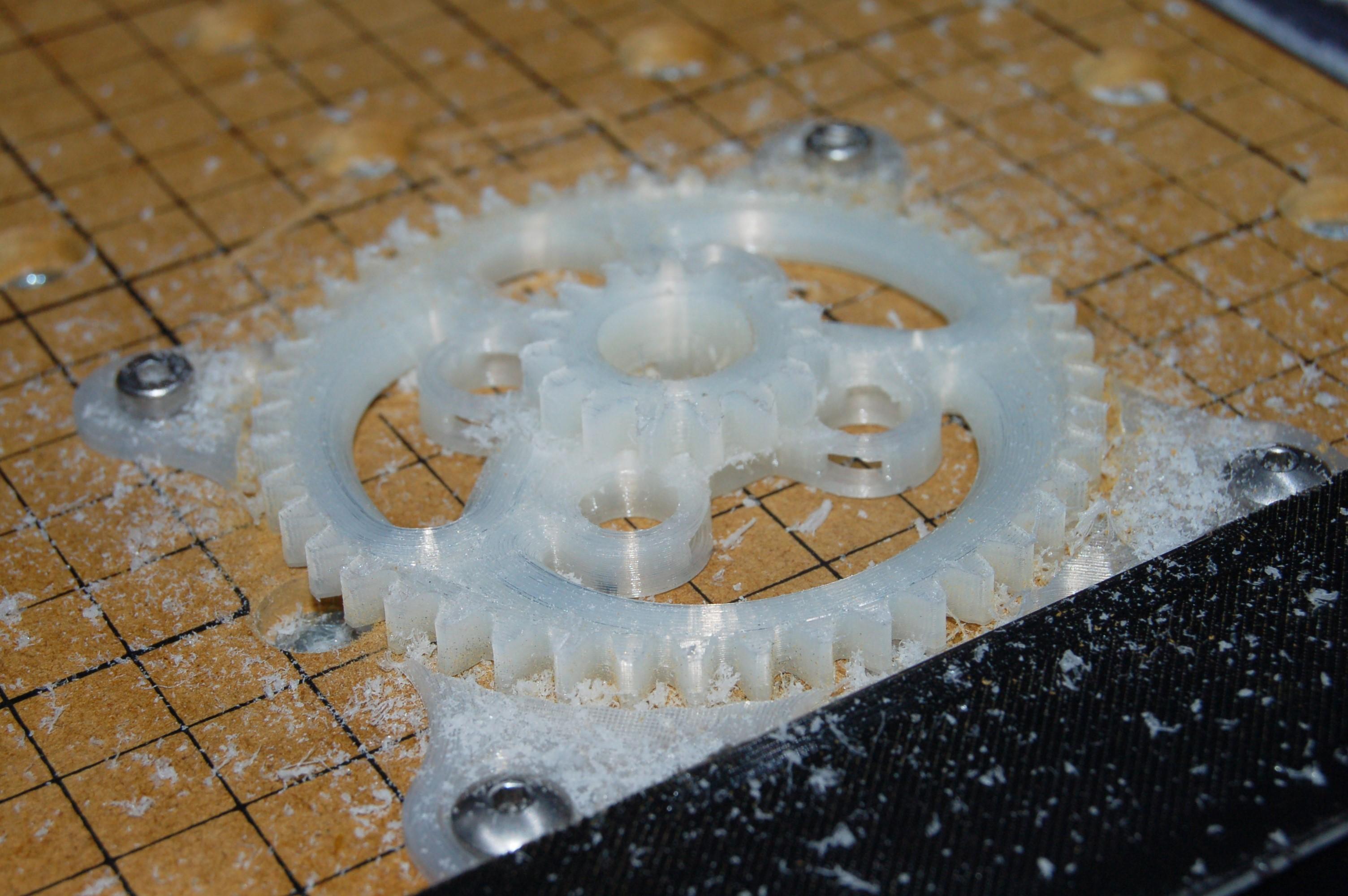
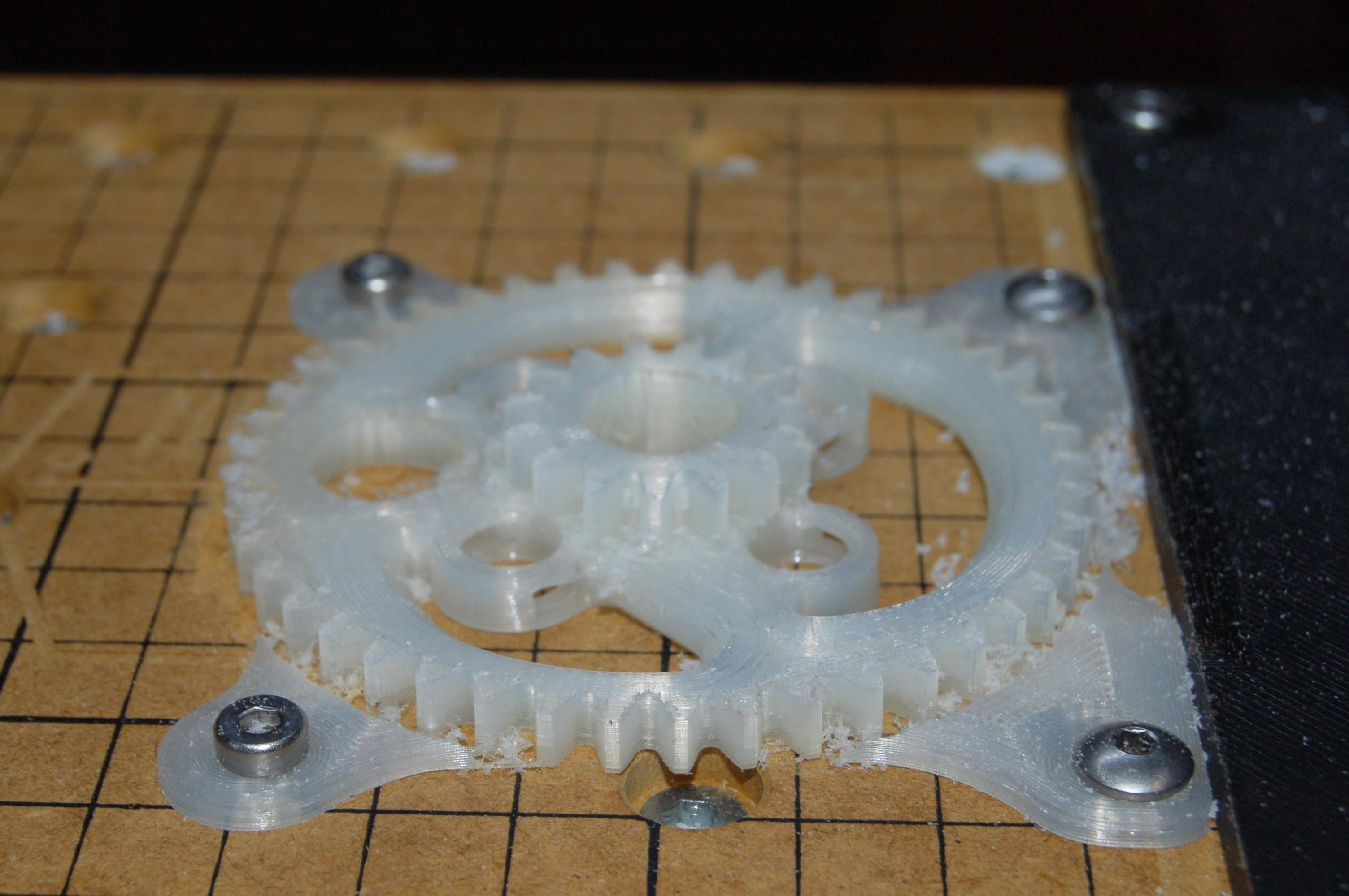
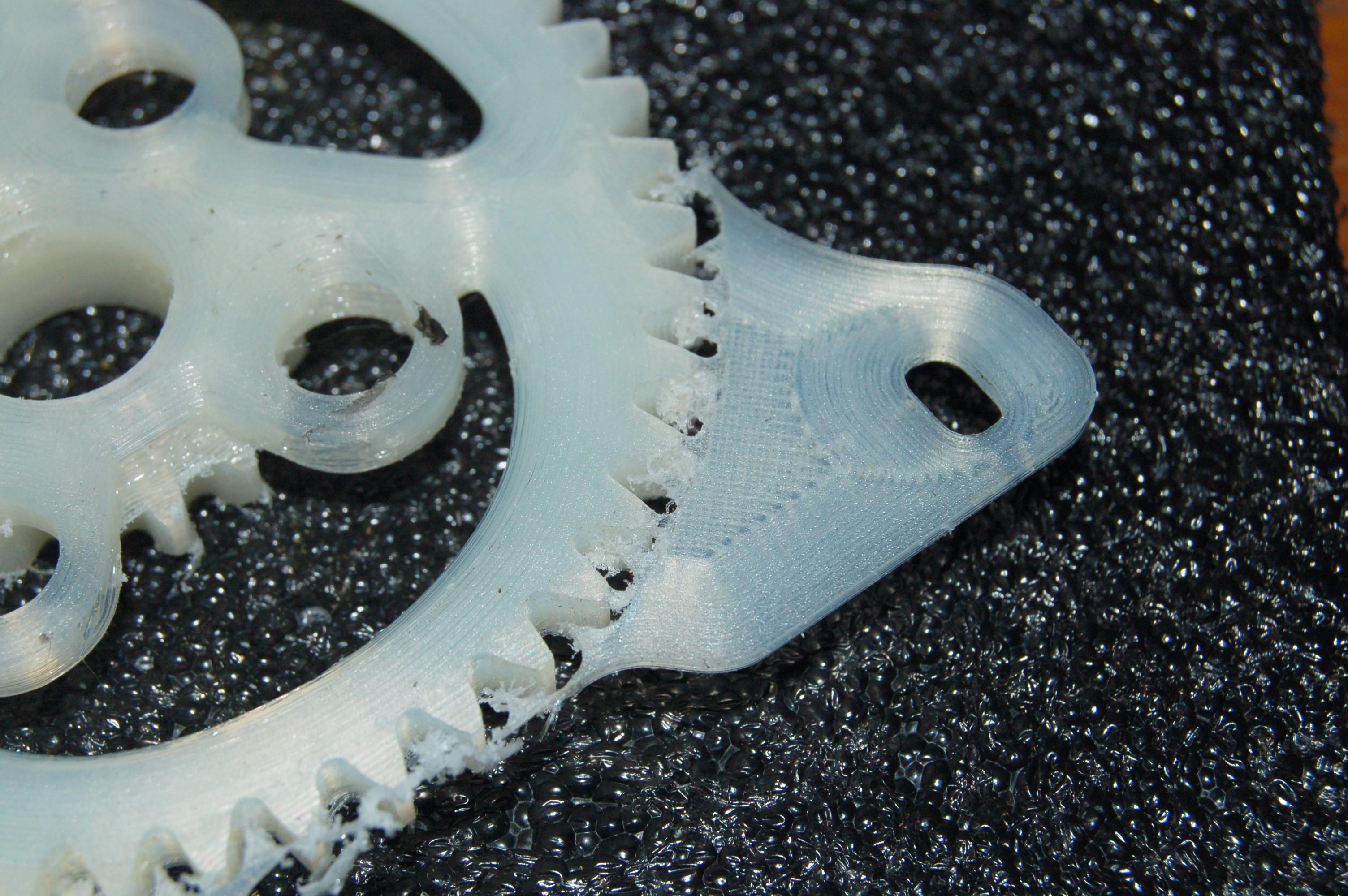
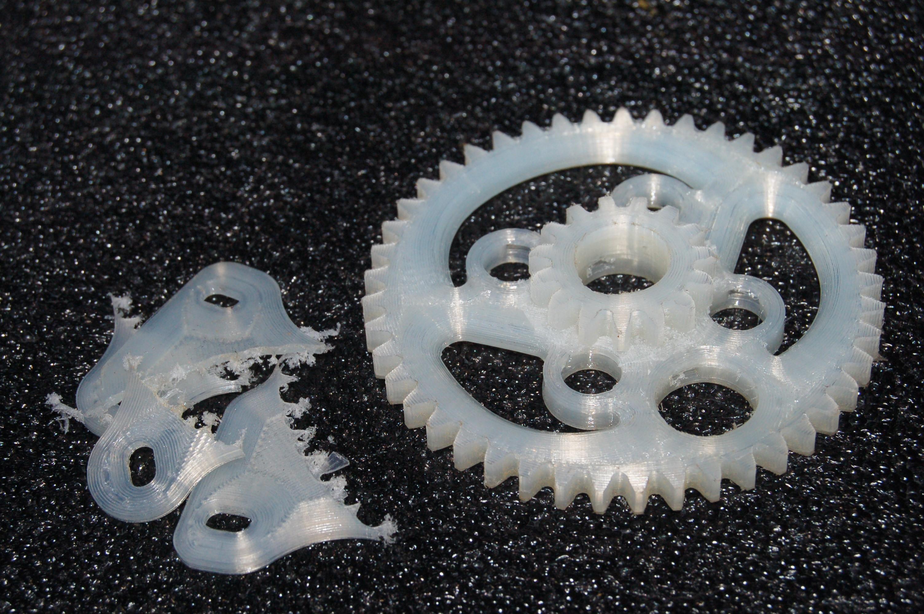
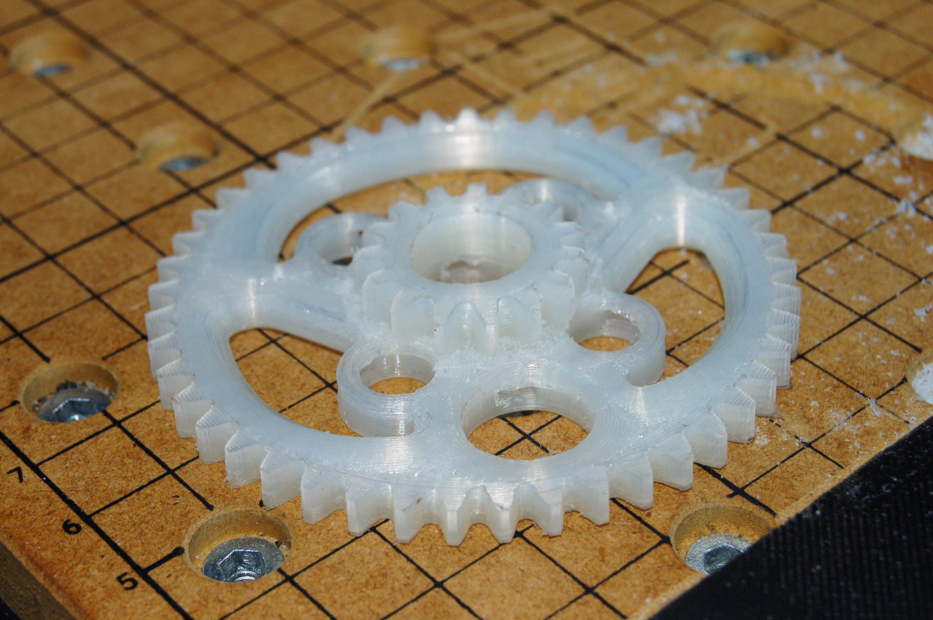
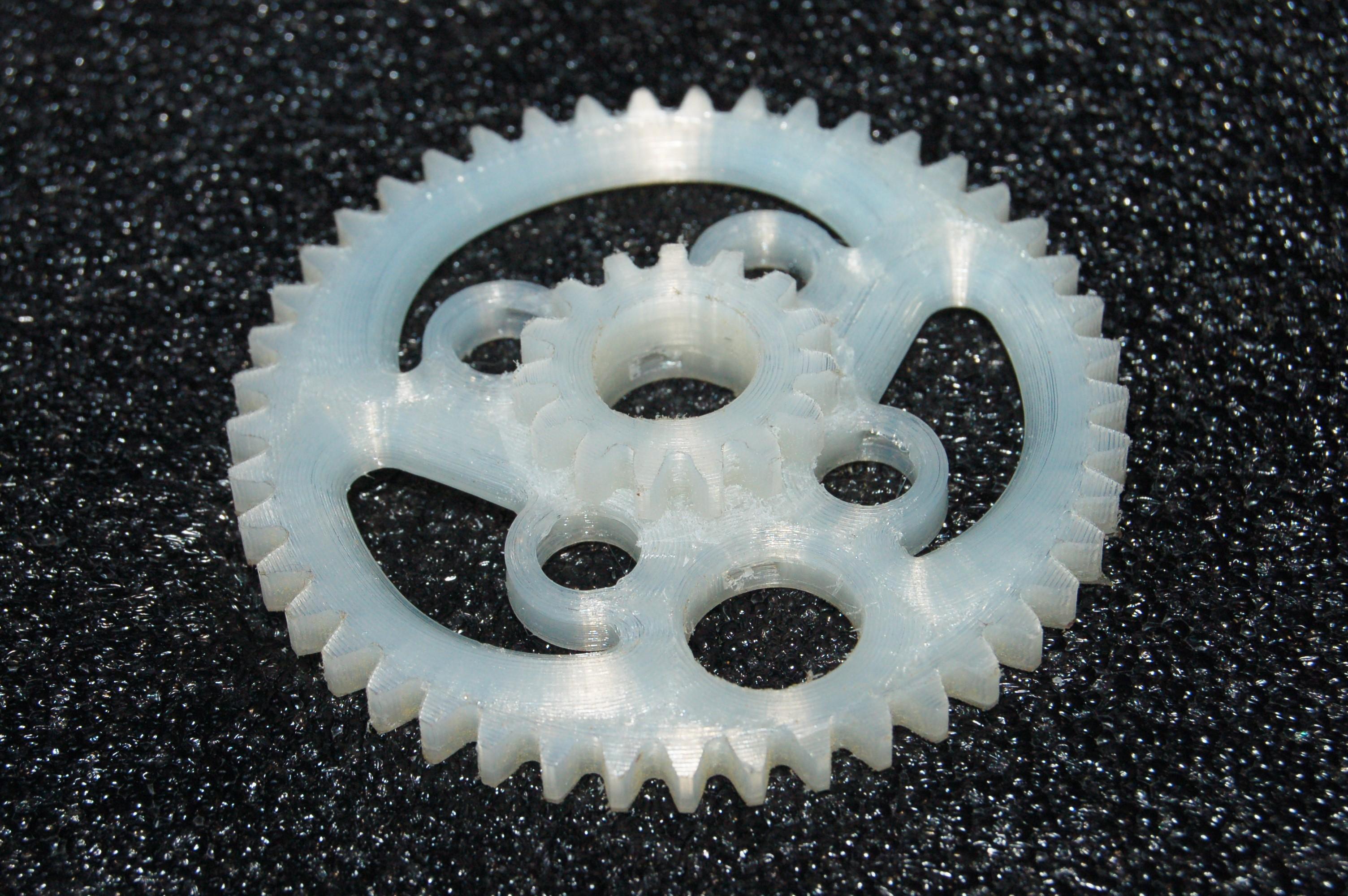
All the previous steps were repeated to produce the final part. The gear blank was printed in Taulman Alloy 910 Nylon material, with extra heat an extrusion multiplier to make it was solid.
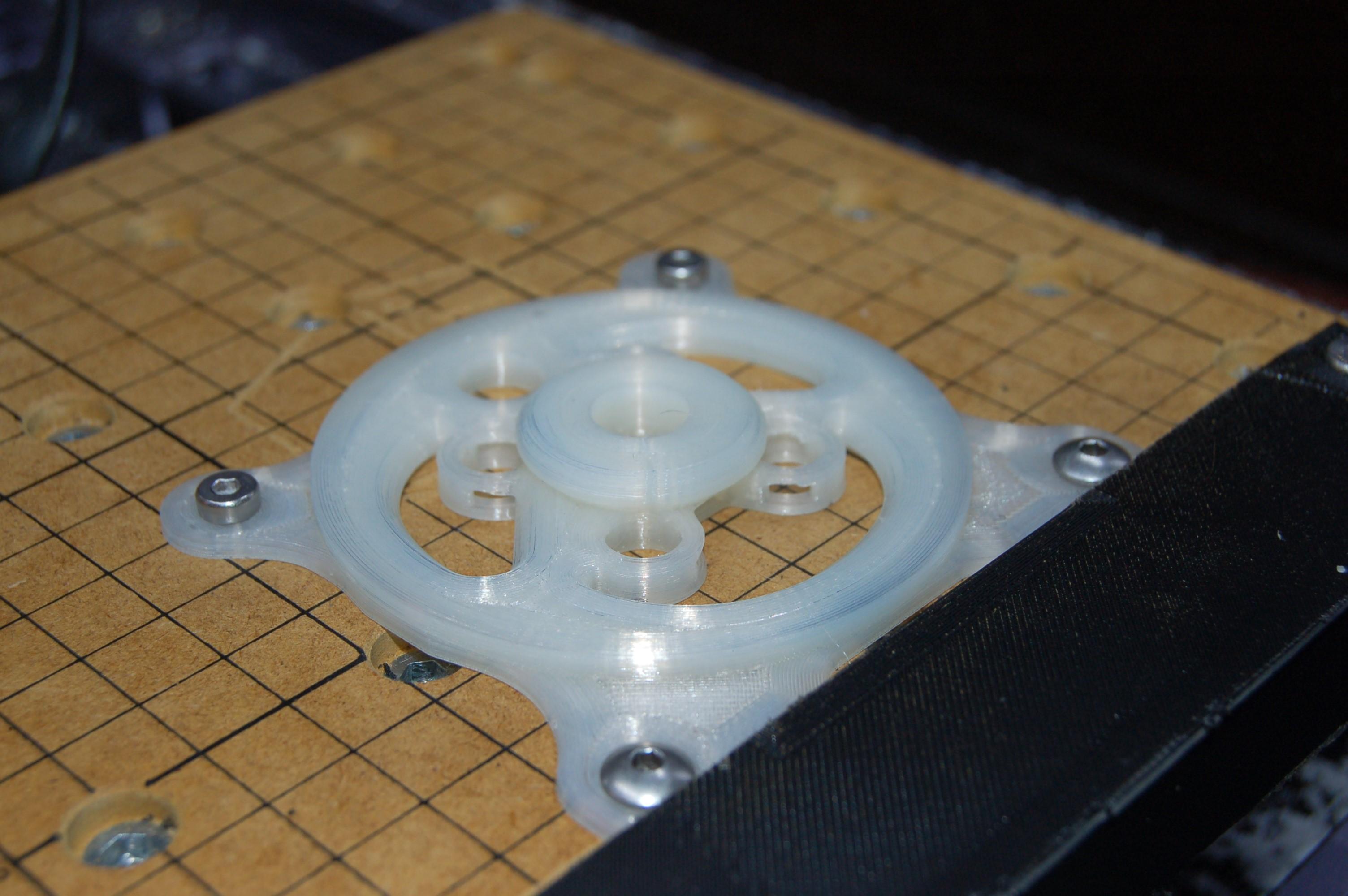
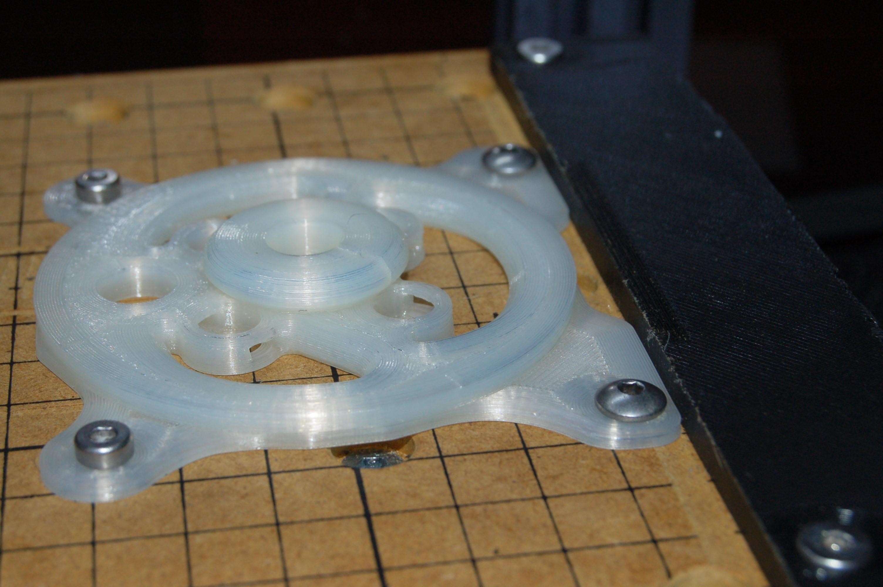
The part was squared against the edge (a straight edge was incorporated onto the blank to reference against the bed straight edge) and then bolted down.
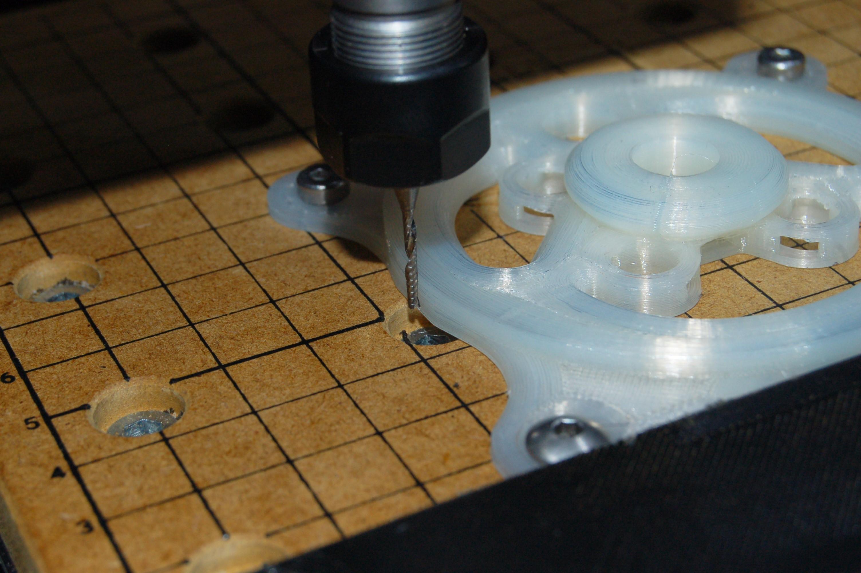
Two contour operations were done to cut the holes in themiddle of the gear, then adaptive clearing was used to cut most of the material to form the gear teeth and then a contour operation was used to finish the surface.
It must be said that machining the nylon was much easier than PLA, likely because of the higher melting temperature and softer material. The O flutes produce a good finish, although it could probably be improved with final passes from an end mill.