Humidity + Servo + Arduino
by callmeappytechie in Circuits > Arduino
14861 Views, 39 Favorites, 0 Comments
Humidity + Servo + Arduino
Hey, guys!!I'm Sridhar Janardhan back with another tutorial.In today's tutorials, i am going to teach you how to control a servo with the data thrown by the humidity sensor.
Objectives: To know how the valve of a door is opened is to water the land when the soil has less moisture content. To know about this you must be familiar with the DTH-11 sensor which is a humidity sensor for the electronics hobbyist.The DTH-11 sensor is a device designed to measure the humidity of it's surrounding. Now let's start to gather the components required for this project.
Components Required:
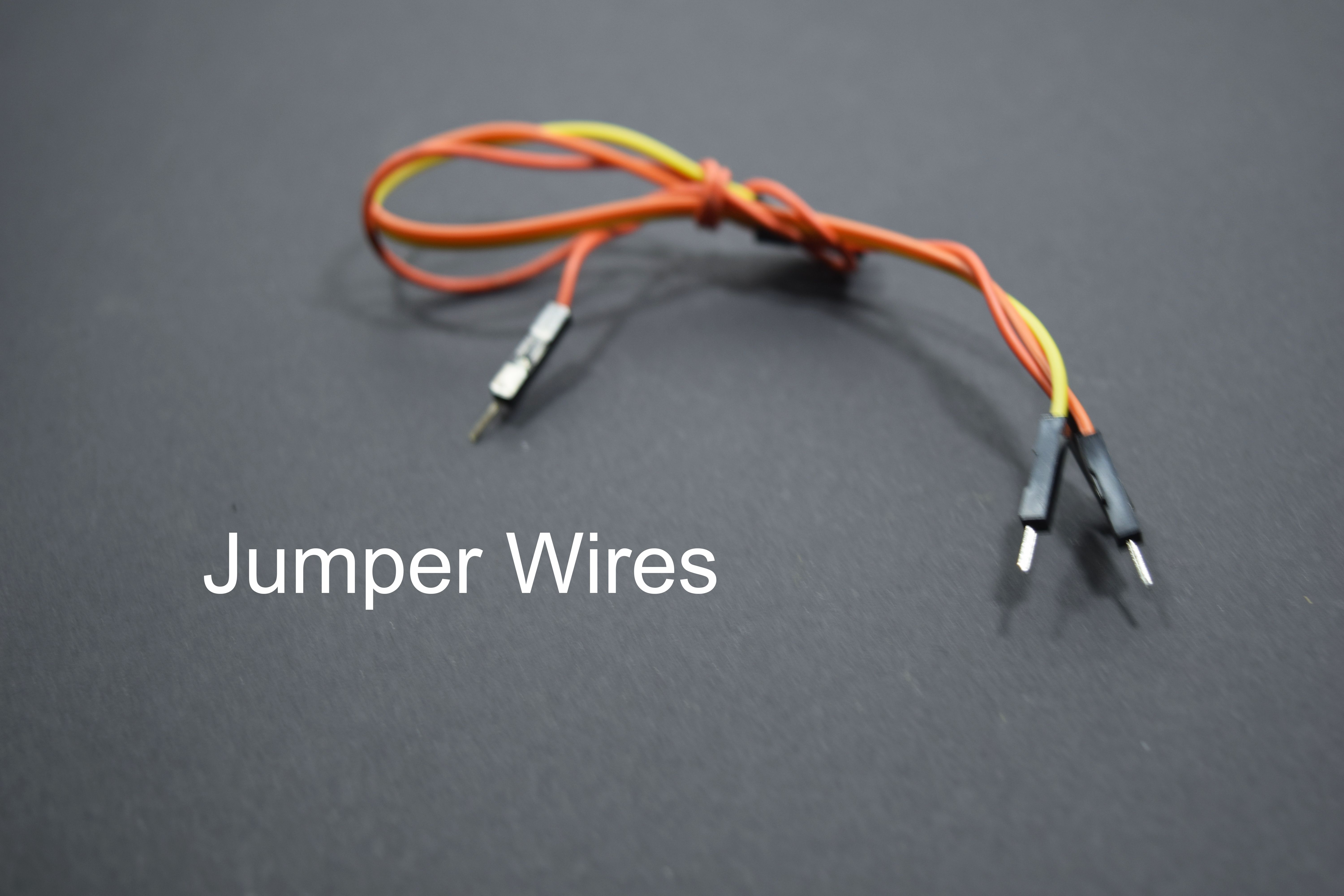
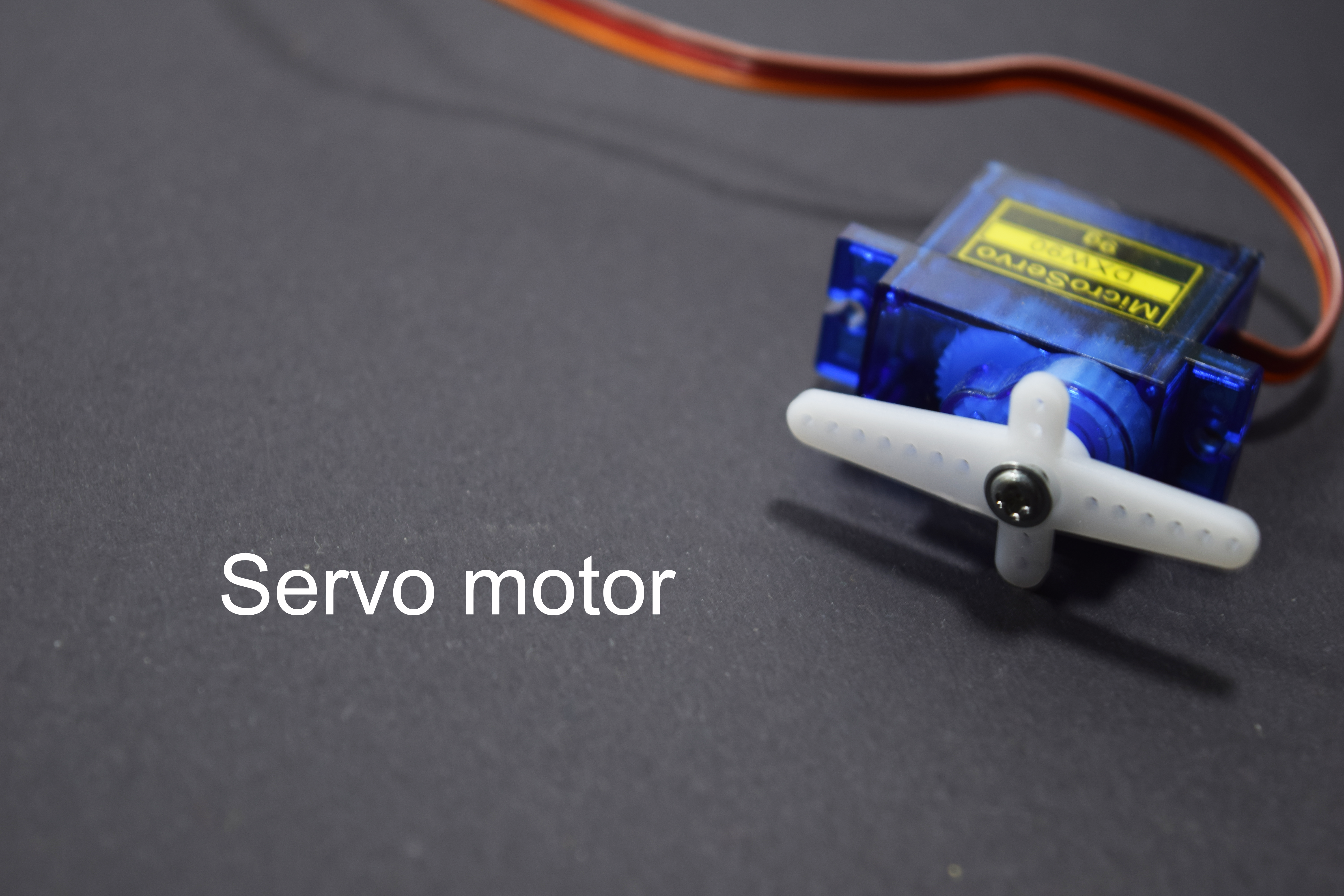
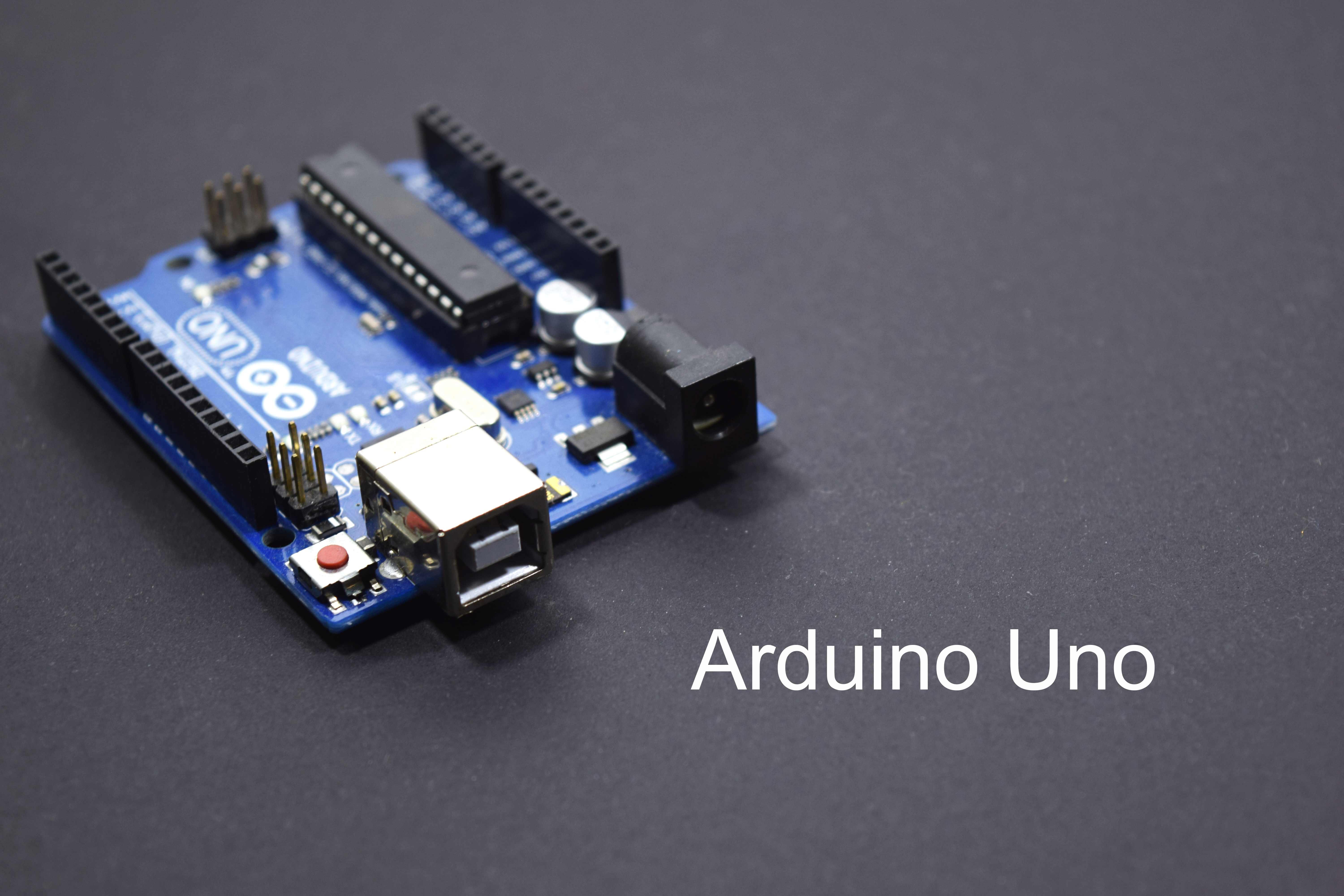
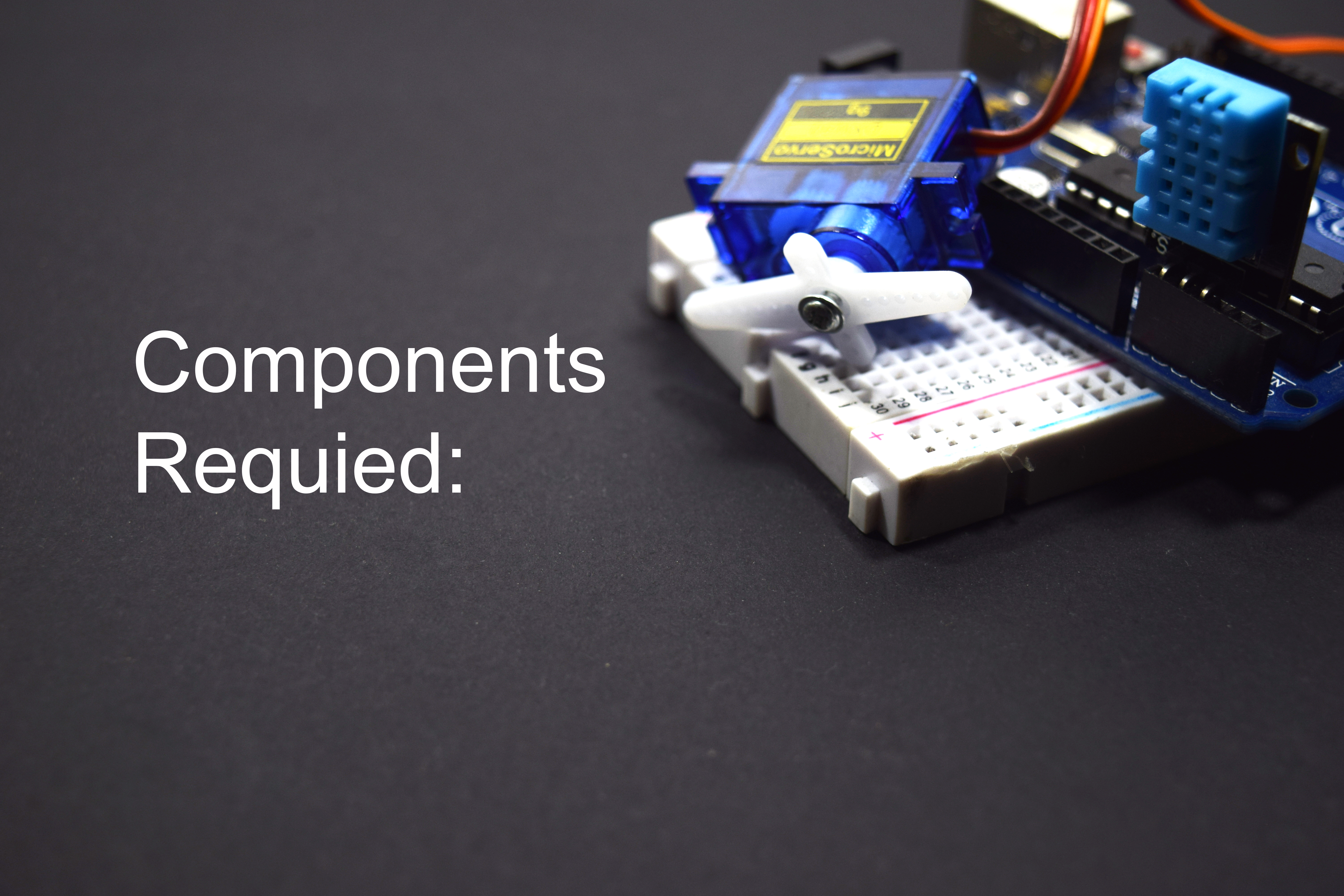
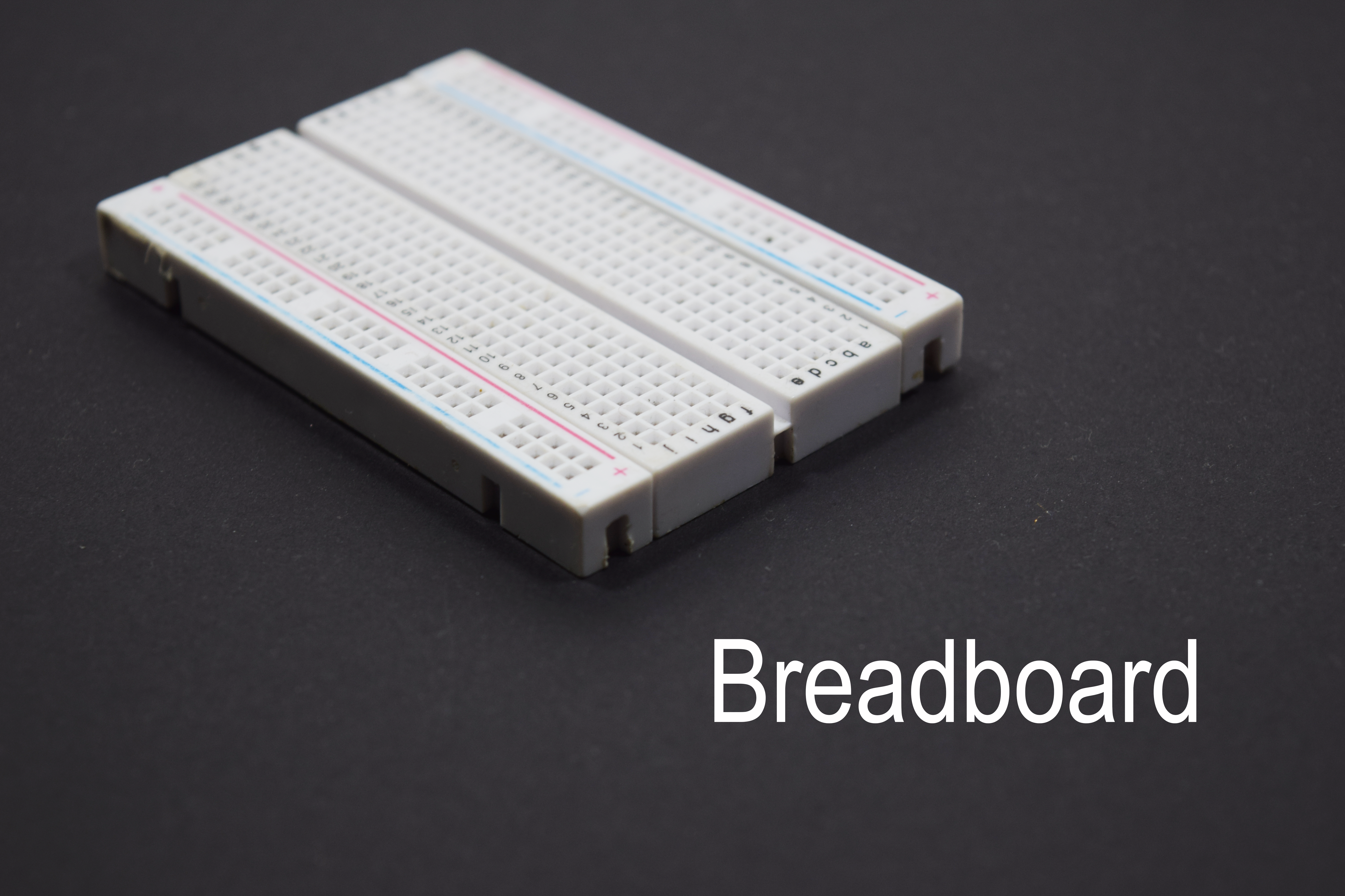
The Components required for this projects are:
- Arduino Uno
- DTH-11 sensor
- Jumper wire
- Servo Motor
- Breadboard
Now let's get into the interfacing part of the Arduino.
Interfacing the DTH-11 Sensor:
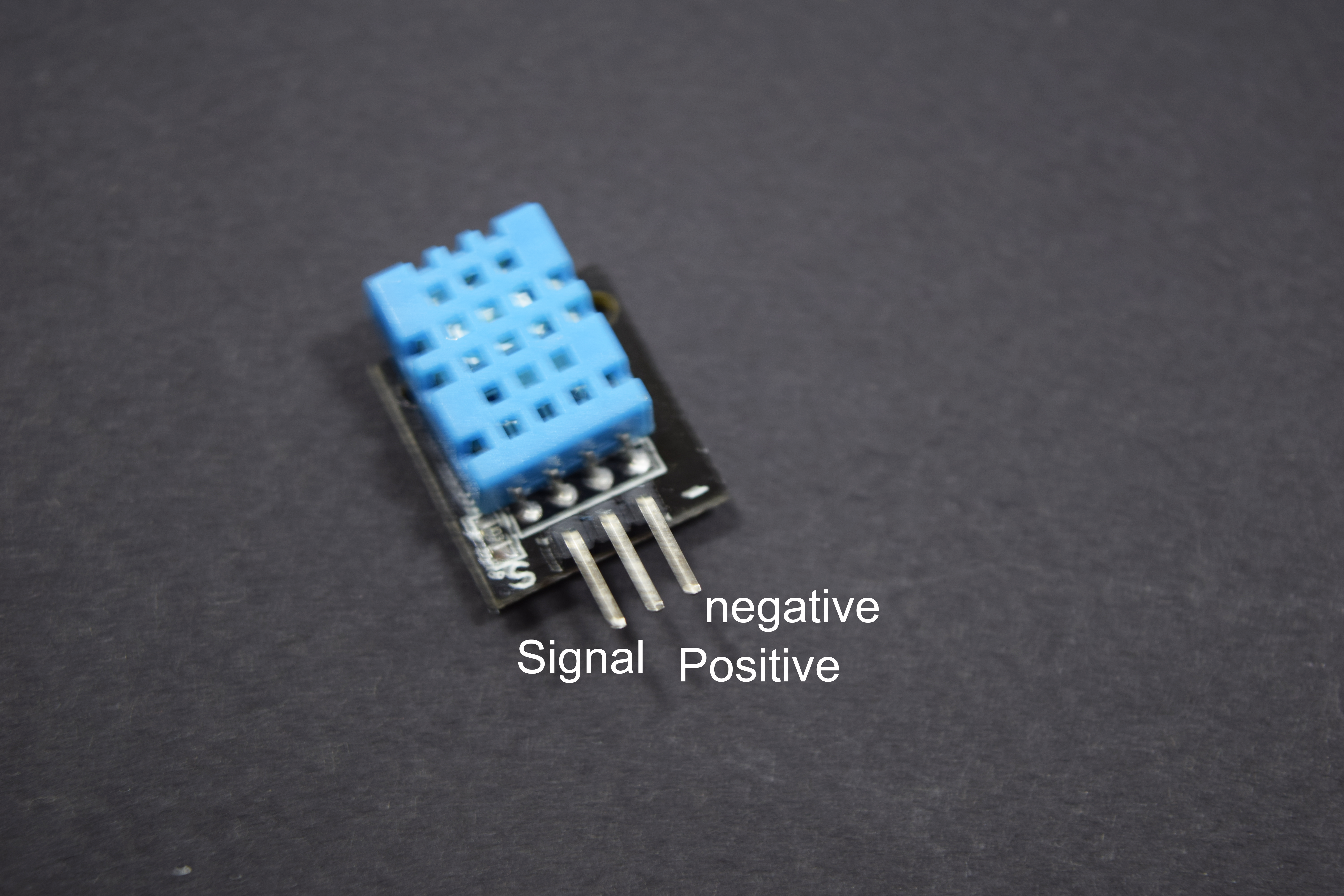
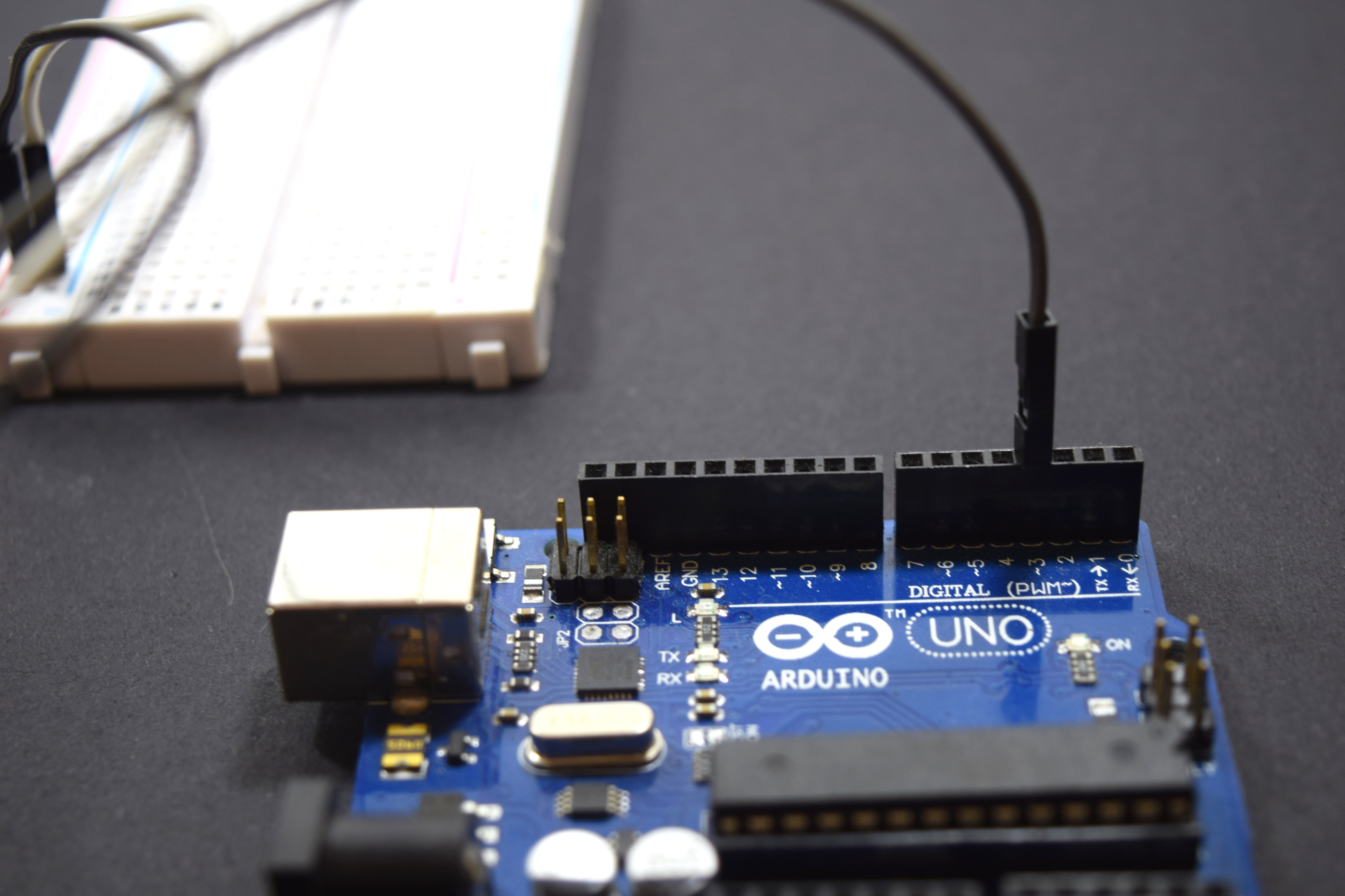
As I explained in the initial part of the Ibles. DTH-11 is a humidity sensor that measures the humidity content around it's surrounding.This sensor throws a data at a regular ping.These data are used by the hobbyist to implement their action as here I have used these data to control the movement of the servo.
Key features of the DTH11 sensor:-
- Operating Voltage: +5 Volts (Can be powered by Arduino)
- the range of temperature: 0 t0 50 °C (error of ± 2 °C)
- Humidity percentage: 20 to 90% RH ± 5% RH error
- Interfacing Medium: Digital
The three pins of the DTH11 sensor are:
- VCC pin: The power supply pin needed to operate
- GND pin: The ground pin needed to ground the components in the circuit
- Signal pin: The pin that sends the data to the Arduino
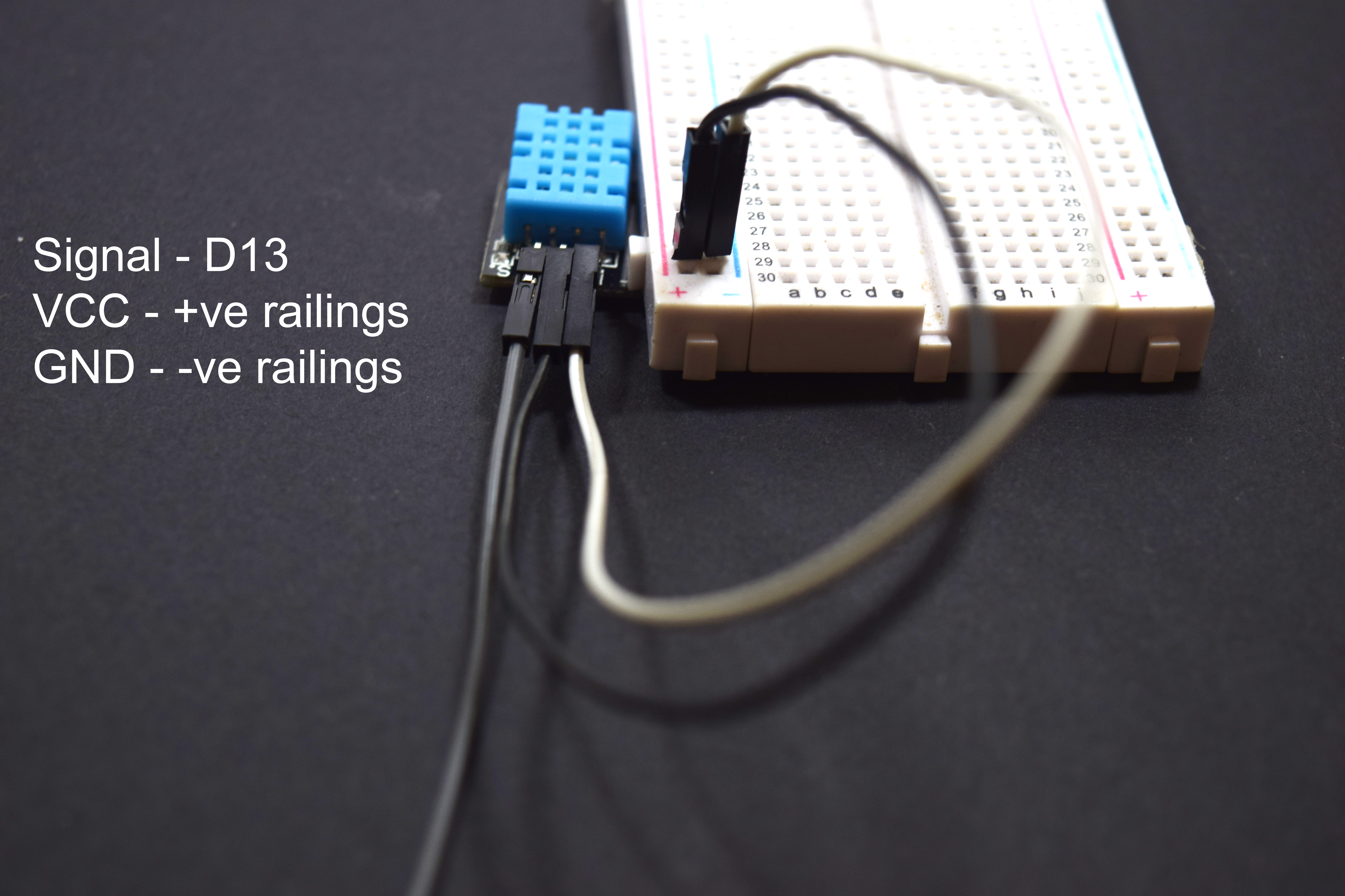
The connection of the sensor is as follows:
- VCC Pin: The power supply is connected to the positive railing of the breadboard.
- GND Pin: This pin is connected to the negative railing of the breadboard.
- Signal Pin: This pin is connected to the Digital pin 3 of the Arduino.
Now let's start interfacing the Servo motor.
Servo Motor Interface:
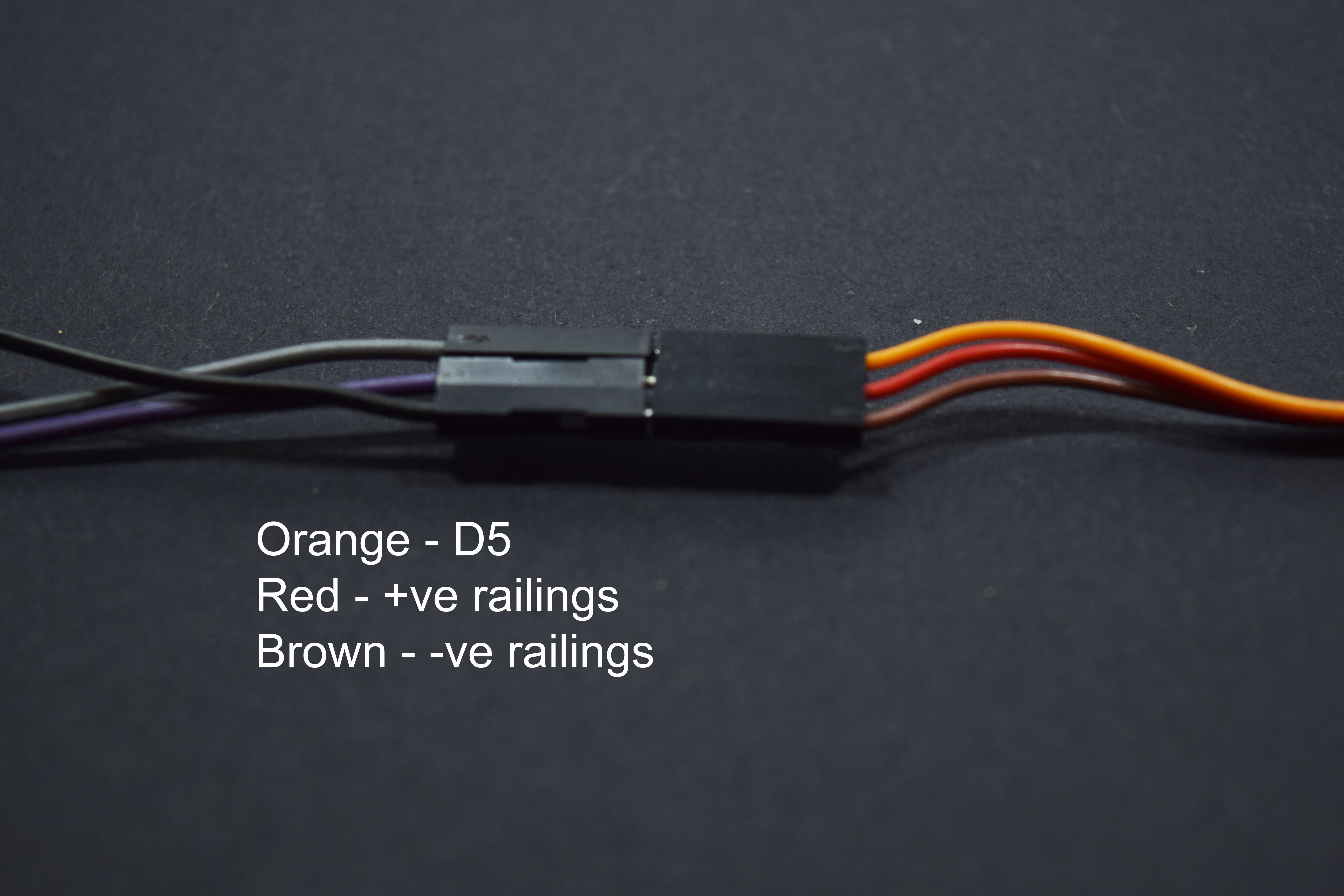
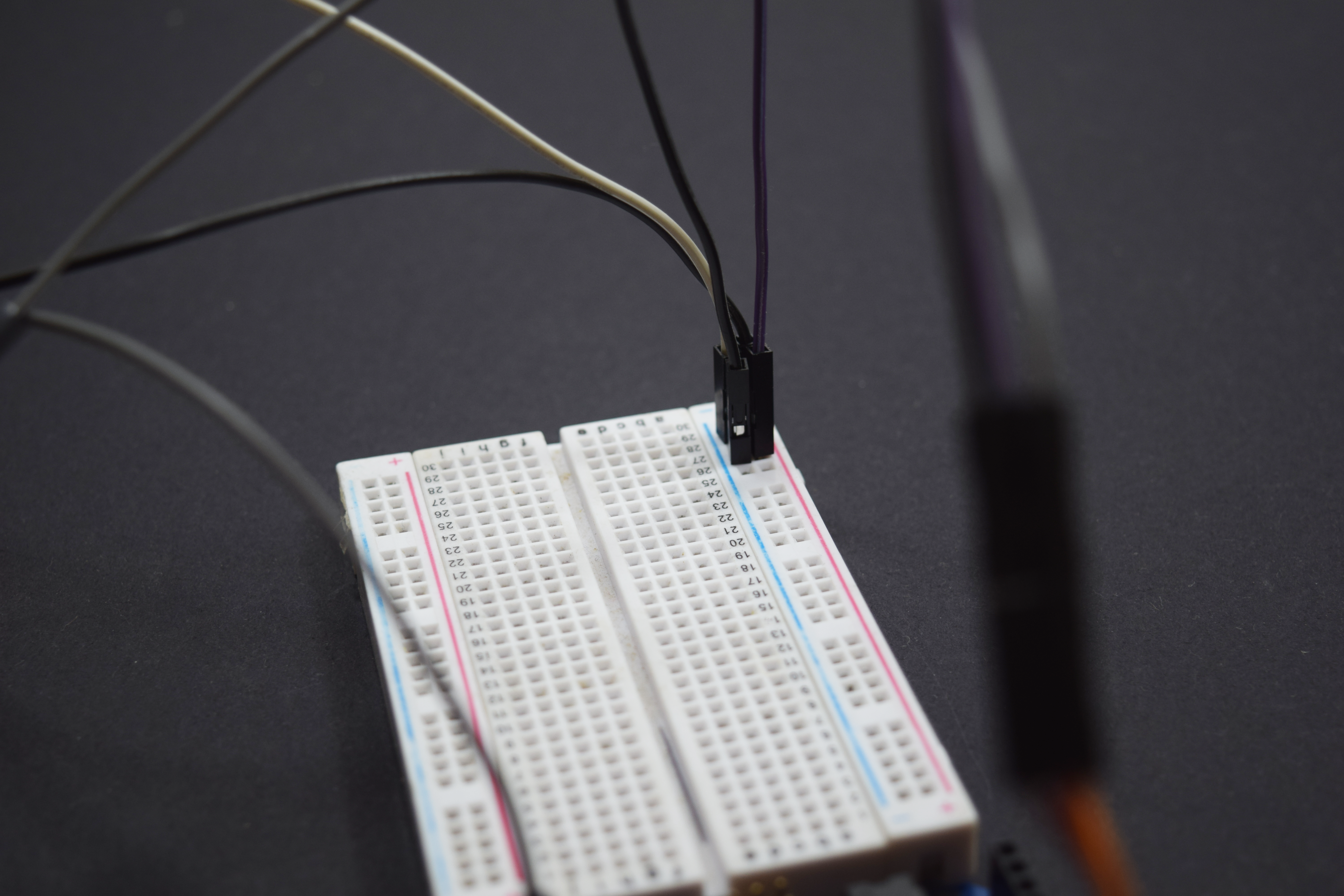
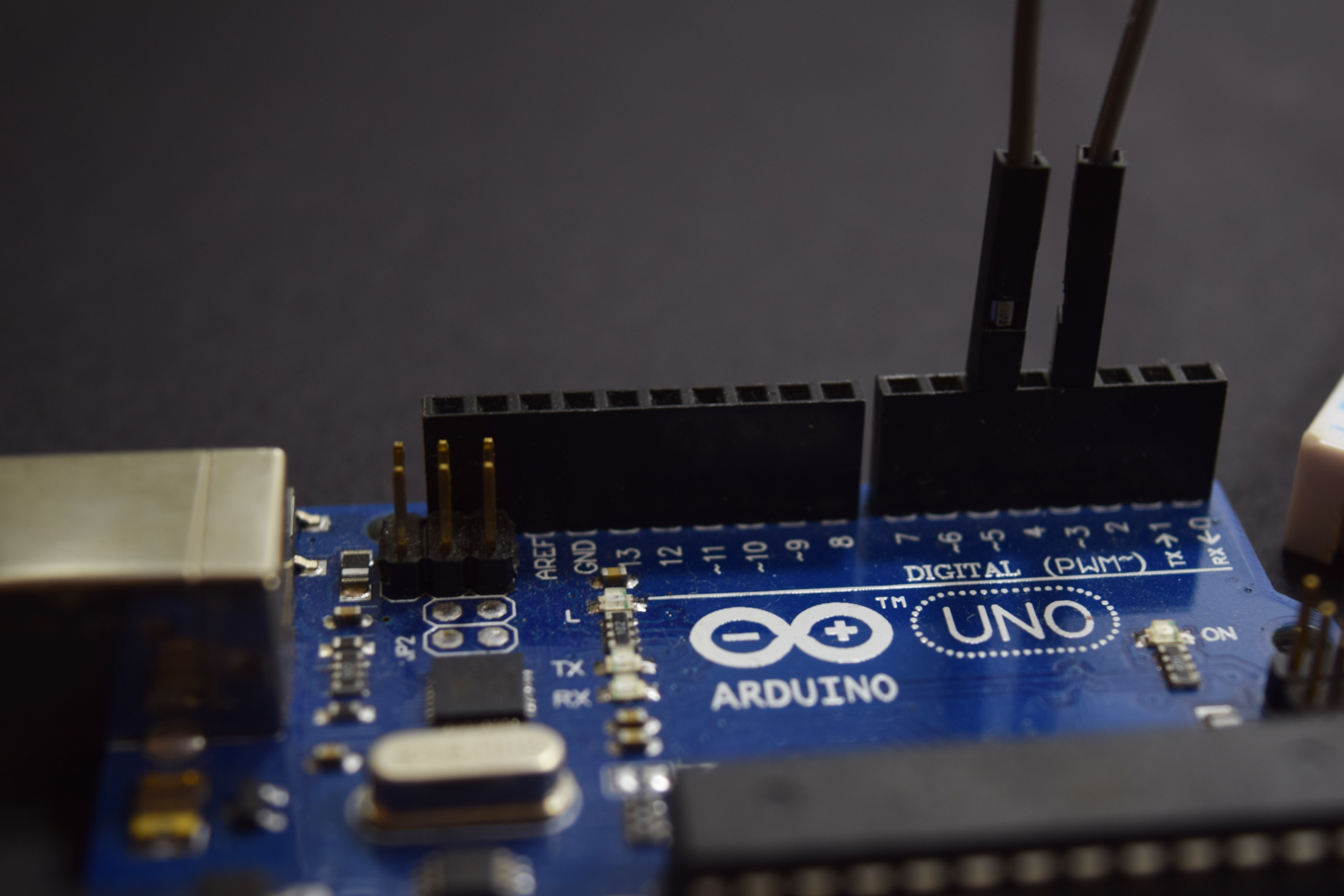
The servo motor is a specially designed motor whose speed and acceleration can be controlled in both the direction.This speed finds its application in the major physical mechanism.
The pin description of the servo motor are:
- Red wire: The VCC pin of the servo.
- maroon wire: The GND pin of the servo.
- Orange wire: The Signal wire.
The Servo connection is as follows:
- Red wire: The VCC pin is connected to the positive railing of breadboard.
- Maroon wire: The GND pin is connected to the negative railing of the breadboard.
- Orange wire: The signal pin is connected to the digital pin 5 of Arduino.
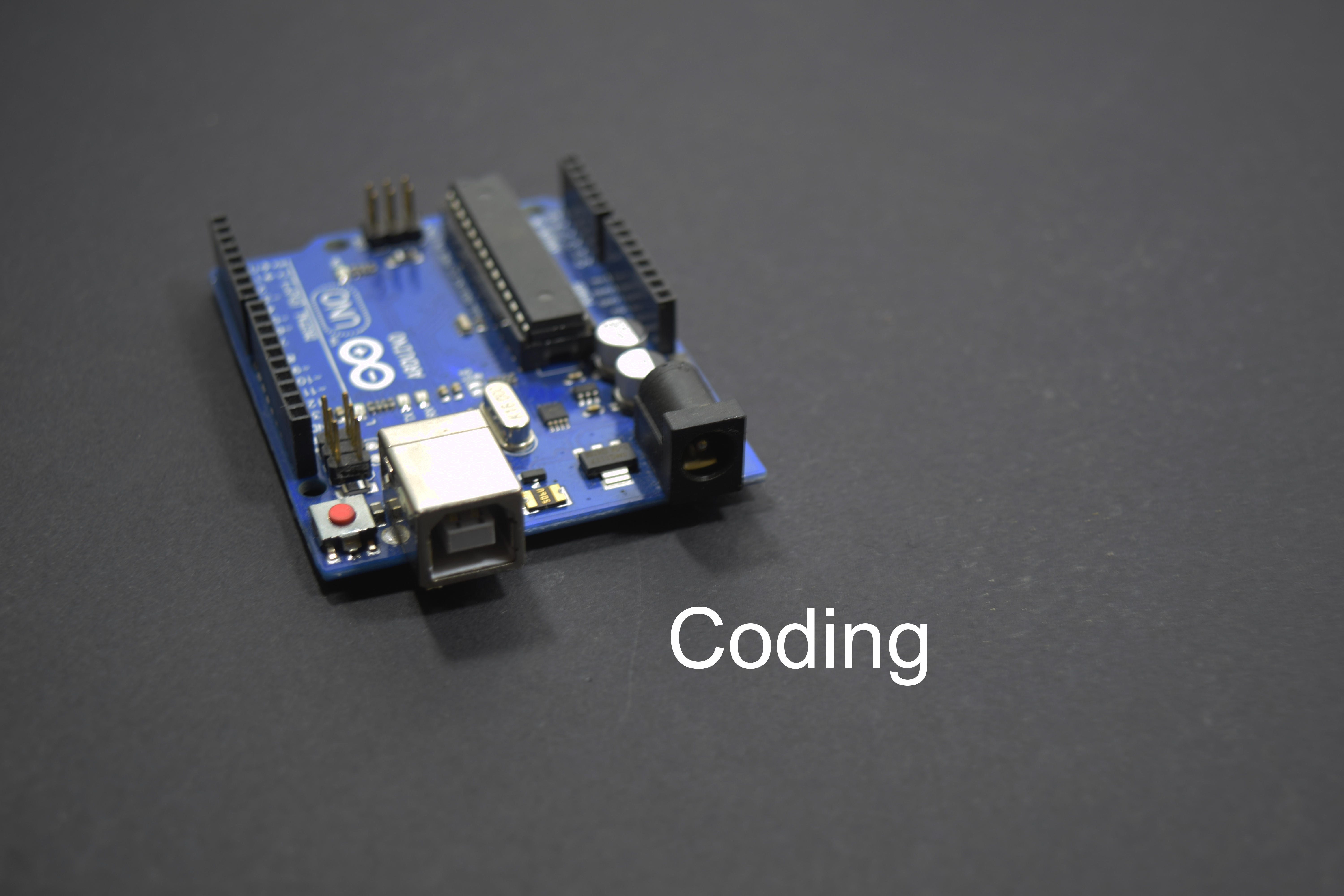
Coding
#include "DHT.h"

#include
Servo myservo;
int pinDHT11 = 2;
SimpleDHT11 dht11;
void setup() { myservo.attach(5);
Serial.begin(115200); }
void loop() { Serial.println("================================="); Serial.println("Sample DHT11..."); byte temperature = 0;
byte humidity = 0;
if (dht11.read(pinDHT11, &temperature, &humidity, NULL)) { Serial.print("Read DHT11 failed."); return;
}
Serial.print("Sample OK: "); Serial.print((int)temperature);
Serial.print(" *C, "); Serial.print((int)humidity);
Serial.println(" %"); if (humidity <= 50) {
for (pos = 0; pos <= 180; pos += 1) { myservo.write(pos); delay(15); }
}
 else {
for (pos = 180; pos >= 0; pos -= 1) {
myservo.write(pos); delay(15);
 }
delay(1000);
}