Howl's Moving Castle Humidifier
by nataliezheng097 in Workshop > 3D Printing
768 Views, 5 Favorites, 0 Comments
Howl's Moving Castle Humidifier


After watching Howl's Moving Castle last summer, I was inspired to make a real life version of the same thing. Since the castle always spews steam from the chimney in the movie, it seemed only right for it to release steam in real life as well. Thus, the idea of a Howl's Moving Castle humidifier is brought into reality.
My name is Natalie, a senior from Irvington High School. This was my SIDE Project in Ms. Berbawy's Principles of Engineering class.
This project was made with the help of 3411 Heaven Media's DIY Humidifier video which explained how humidifiers work and how to make one, I just downsized the components to make it smaller for this project. I also used Howl's Castle from the Studio Ghibli theme park to model my castle after because the actual castle in the movie was kind of... too magical to be able to hold a whole lot of water.
Supplies
Software:
- Fusion360
- PrusaSlicer
- Orcaslicer
Tools:
- 3D Printers
- Original Prusa MK3S+
- Original Prusa MINI+
- Original Prusa XL
- Flashforge Adventurer 5M
- Soldering station
- WORX airbrush
- Foam and regular paintbrushes
- Dremel
Filaments:
- Regular PLA
- Hatchbox Brick Red
- Polymaker Starlight Jupiter
- Polyterra Arctic Teal
- Polyterra Cotton White
- Amolen Bamboo Wood PLA
- PETG (any color),
Paint (I used air brush but just using acrylic paint or even spray paint works as well):
- Airbrush
- Gun Alloy
- Oil Discharge
- Plasma Fluid
- Snow White
- Green
- Brown
- Orange
- Acrylic:
- Silver
- Base Grey
- Hooker's Green
- Cadmium Red
- Raw Sienna
- Raw Umber
- Burnt Umber
- Green
Electronics:
- Push button
- stranded core wires
- 2 ultrasonic piezoelectric disk
- USB splitter
- 2 microusb to usb cables
- Small DC fan
- Portable charger (or a 5V charging brick that has USB)
CAD the Water Chamber


This is the real heart of the system where water is stored, energized, then circulated to the pipes. To make a water chamber:
- I took the measurements of my piezoelectric disks
- I then CAD-ed a box with two extruded circles to place the disks in.
- I made sure there is a bit of clearance between the disks and the ground in order to promote better airflow for the mist produced by the disks by extruding the four corners down as legs.
- This box will be 3D printed so that there are no seams where the water can leak out.
CAD the Steam Chamber


To make the steam chamber, start with making the lid.
- I took the measurements of the DC fan's dimensions along with the vacuum pipe's diameter and the steam chamber's legs, making sure to keep the placement of the screw holes for the fan in mind.
- I made the lid then made the box underneath it using the lid's dimensions. I made clasps with very tight tolerance (around 0.005in) in order to make a lid that can click shut.
Print the Water and Steam Chambers


Using Prusa Slicer
- I printed the water chamber in PETG at 60% infill.
- Then printed the steam chamber using regular PLA in any color since this will be on the inside of the final print.
Note that although the picture shows supports for the water chamber's front, this is no longer needed because it is an unused feature in the final project.
Wire in the Electronics


- I unsoldered the push buttons on the two piezoelectric disks.
- Then I soldered the stranded core wires to the buttons' previous joints.
- I soldered those wires to the pushbutton like the 3rd and 4th image shown above.
- After plugging in the two micro USB cables to the socket on the boards and connecting the other ends to the female end of the USB splitters, I plugged in the male end of the splitter into the 5V portable charger to make sure the circuit works properly. (note: it does not need to be connected to a portable charger, a 5V charging brick will work as well).
- Make sure to put the disk on water.
Insert Everything Onto the Lid


- I inserted the piezoelectric disks into the round slots at the bottom of the water chamber.
- Then I placed the box onto the steam chamber's lids along with the vacuum pipe and DC fan.
- I turned on the piezoelectric disk and fan to make sure the system still works.
Note that users should turn on the disks first and let some steam form before they turn on the fan.
CAD Castle Base


- I started with a sketch on the XY plane and sketch out a circle and a rectangle connected to it halfway through. Then I took the dimensions of the steam chamber and add that to the middle of your sketch with around a 0.02inch tolerance.
- I extruded this up by 2 inches and then the circle by 5 inches.
- I sketched a shape like the one on the 3rd picture in the YZ plane.
- I then revolved the shape of the face in the sketch.
- Then I revolved the curvature outside in a cut to shape the previous cylinder into a proper globe shape.
- I extruded the flat top of the shape.
- I extruded the rectangle from the sketch equally horizontally to make the box that will become the first "house."
- I revolved the top sketch's triangular shape in order to make the connection between the face and the house more full.
- I used the plane at an angle tool to make a plane and extruded a second home.
- I did the same for the third home on the other side.
- Finally I extruded out the exposed parts of the revolve on face to make the sides of the body.
Add in Some More Parts to the Base


- I started by CADing the two water towers in the back of the castle
- I made the top dome by using offset plane then sketch out the shape of the dome then used the revolve tool to make the dome.
- I extruded the bottom of the dome all the way down.
- I did the same for the smaller dome, making sure to not fill in the slot where the steam chamber is supposed to go.
- I connected the top of the two towers using the loft tool.
- Then I added a small opening to the back where all the wires will feed into, using the largest part of the cables as a baseline for the dimensions of this hole.
- Then I CADed the rest of the houses
- These houses will not be at an angle but rather on the sides of the castle. This is mostly dependent on how the creator wants the castle to look so be creative with its dimensions. That being said, I went with just rectangle boxes.
CAD the Face


- Using the emboss tool again, I sketched two triangles and then debossed the trapezoid shape it forms in between in order to make the open-mouth shape of the castle.
- Using the push-pull tool I adjusted the proportions of the mouth.
- I added a sketch on the bottom of the castle and drew a circle that is the exact size of the front of the castle.
- I offset a smaller circle inside (Making the difference between the two circle is how thick I wanted the teeth of the castle to be).
- I drew lines from the center of circle into edge of the mouth, I made three on each side.
- I extruded each rectangle formed by the circles and line out to form the crooked wooden-like teeth of the castle.
- Then I used the loft tool to make a more sturdy connection between the face and the base of the houses (it also accentuates how the face should be coming OUT of the castle and not a separate part of it).
- I used the hole tool to create two threaded holes on the face of the castle.
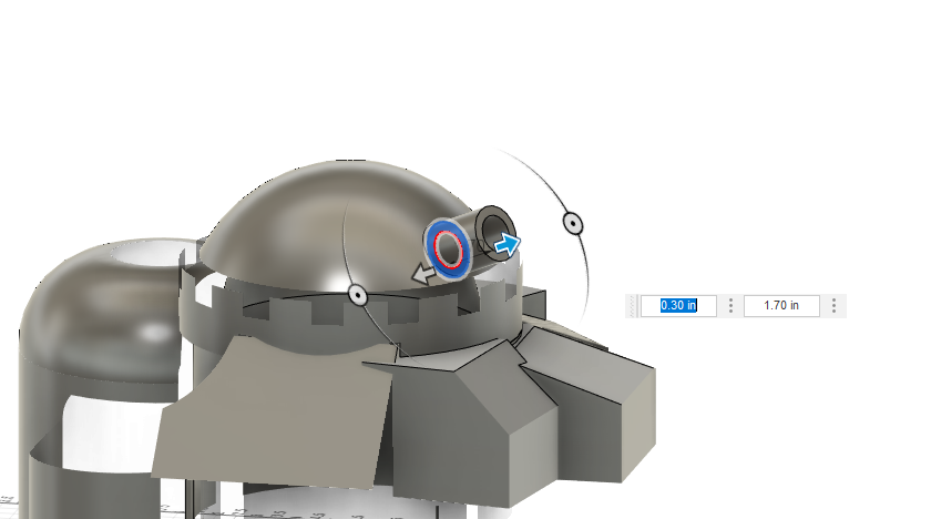
- I made two corresponding poles that are threaded the same way and for one of them, extrude around 4 to 5 inches before using the sphere tool to make a rounded top at the end of the pole. This is the "left eye" of the castle.
- To add a visor, I used the sketch tool on the left eye and sketched a circle and offset a smaller circle from it (note: make sure the diameters of BOTH circles are not smaller than the diameter of the pole), I sketched a straight line from the center of the circle to both sides the length of the diameter. I then sketched two more lines at 60 degrees, forming 3 triangles (see imaged 6 and 7).
- I extruded the two arcs formed inwards by around half an inch.
- I then made the visors by taking the two circles' difference as the thickness and then extruding it out by 2 inches using the same method previously used to make the holes for the visors to make the extensions to fit them in, using around a 2 degree tolerance to insure a proper fit.
- For the other pole, I made a flower shape using arches on a sketch at the top of the threaded pole. Using an offset plane to offset around 4 or 5 inches, to make the same shapes again only a bit smaller (note: I made sure that the number of arches on both sketches are the same).
- I lofted the two.
- I inserted flat cylinders around 1/3 the way up and another at around 2/3 of the way up and then used the torus tool to add a donut shape at the top. I extruded the hole in the middle of the "donut" to complete the cannon look for the right eye.
CAD the Cap


The Cap is designed to be removable from the rest of the body in order to have easy access to refill the water chamber.
- I used the sphere tool to add to the top of the model. Then I used the extrude tool to remove the excess bottom of the sphere.
- I added a sketch to the side of the sphere, and sketched a rook pattern onto the sketch. I used the emboss tool to extrude out the wall pattern onto the sphere.
- I used the plane at point tool to add a plane at an angle into the sphere.
- I sketched and extrude a "cannon" shape. I made sure to extrude the hole all the way so that there is air circulation in the castle for the dc fan.
- I mirrored the cannon so there is a second, symmetrical one on the other side.
- I added holes to the underside of the cap and corresponding dowels to the top of the castle base.
- I added a slot to place the push button of the circuitry at the top of the base model.
CAD the Rest of the Details


- Chimney
- I added a chimney where the steam will exit by using the plane at point tool and offset plane to set up a loft.
- I used the axis through cylinder tool to create a tunnel that will connect to a point on the inside of the castle.
- I used the section analysis tool to make sure the path properly connects to the exit point.
- I used the previous dimensions for the vacuum pipe on the Steam Chamber lid for the hole.
- Windows
- These will largely depend on personal taste because I did not follow all the windows in the online photo, but to add windows, I sketched the shape of the window onto the selected house, then extruded the window frame out by 0.05 inches, tapered at a 45 degree angle. Extruded the inner window "panes" inwards by 0.05 inches to make the difference more pronounced.
- I repeated this for all of the windows, I purposely left some of the houses with no window for variety
- OPTIONAL: To CAD balcony in the castle
- I created the sketch on the home I wanted the balcony to be on.
- Then I sketched out the shape of the balcony, I made sure to include arcs and a rectangle for the standing platform.
- I extrude the platform out and the rest of the shapes in.
- I added a sketch on the platform and sketched some circles on the outer edge of the platform.
- I extruded the circles.
- I added a sketch on the plane on top of the circles then drew a continuous line through the center of each circle.
- I used the sweep tool to complete the railing of the balcony.
OPTIONAL: CAD the Leg


The legs are the castle are designed to be removable because the addition of them takes up a lot more space. The completed pictures I have above don't even have legs attached, therefore depending on your taste, it is optional to include them.
- I started with a sketch on the plane that faces forward.
- I sketched the silhouette of the leg's shape using arcs and lines.
- I revolved this shape by the line in the middle.
- For the feet, I used the same revolve method and formed an individual toe.
- Then I used an extrude to form a flat bottom for the toe to stand on.
- I copied the toe 2 more times and oriented them on the feet to make proper toes.
- At the other end of the leg, I extruded out a cylinder to use as a dowel for the leg to be inserted into.
- I copied the exact leg once and placed it in the back as the back leg, then I used the mirror tool to make the legs on the other side of the castle.
- I used the end of each extrusion to cut into the castle to make space for the dowels to go (making sure to line up the legs so that the bottom of the legs will not be farther then the bottom of the castle as the legs are not made to actually support the castle!!).
Slice Things Up


Now that all the parts have been CADed, it's time to print them on the printer
Now I'm sure that at this point it would be evident that the entire print is simply too large to be printed on one Prusa MK3S+. To remedy this, I split the base print into 7 smaller pieces
Note that these may be changed based on the dimensions of your own printer
- I split the face from the rest of the body
- I split the entire build in half vertically, using the bottom of the lowest house as a marker, I used the dowel tool in the connectors setting
- Split the two water tanks from the rest of the body, using dowel connectors (I used snap joints but dowels seem to work better).
- I now have 5 pieces altogether: the head, top with houses, bottom that connects to the houses, and the top and bottom of the water tanks
- I sliced the bottom into two more pieces, creating 7 pieces total
Note that you should cut the pieces more to insure they fit on the printer you have but minimize the slices on the tunnel that connects the vacuum pipe to the chimney because more potential openings means more potential steam leaving and diminishing the effects
OPTIONAL: But if you have a printer that can print in multiple colors (like the Prusa XL), you can do something like I did above in image 10 with the center piece that has all the windows and houses and print the details in different colors
- White is Polyterra Cotton White
- Blue is Polyterra Arctic Teal
- Red is Hatchbox Brick Red
- Brown is Polymaker Starlight Jupiter
To print the leg:
- I split the leg into halves first by the joint and then in half in length so that it laid face down onto the platform properly, I used connectors to secure them.
- I added supports for the toes that may have some overhang.
I printed leg using a Flashforge Adventurer 5m which uses Orcaslicer but this can be sliced and printed with Prusaslicer and a Prusa Mk3 as well
To print the cap, I split it in half and use snap joints connectors (again dowel connectors may work better).
Paint the Pieces


I painted the pieces, I did this before assembling most of it. Depending on the quality of print, you may need to sand but mine didn't need any.
- I used the airbrush to set a basic tone for each component
- For the water tank I used a mixture of 80% gun alloy and plasma fluid along with two drops of snow white
- For the wood, I used a mixture of 75% brown and 25% orange
- For the cap, I used a gun alloy and snow white mixture at differing opacity for shading effect
- I used acrylic paint and a foam brush to accentuate the worn-down feel on the CAD
- I used silver for the water tank with an addition of red oxide and hooker's green to give the appearance of moss and rust forming
- I also used regular paint brushes to paint some vines and flowers using green and red
- I used raw umber, burnt umber, and raw sienna in random strokes (in the same direction!!) to give the feel of polished wood.
- I used black acrylic paint to paint window frames and blue acrylic paint to paint the window panes.
Assemble the Pieces


This step should be pretty intuitive as it will largely depend on how the model was sliced in the first place.
- I made sure to use the right dowels for the holes and everything connected together snugly. The seven pieces I had cut are connected as shown above.
- I had some trouble with tolerances for the dowel which I used a dremel for to widen the hole
- After the model is assembled, I placed the steam chamber and water chamber along with all the attachments in place.
- I attached the vacuum pipe to the opening and the tunnel and place the push button in the slot near the top of the castle. (See images 7-9).
Note that some pieces may need to be glued on depending on your pieces' tolerance.
Documentation


I made sure to document each step that I took into my engineering notebook. Please note that in the process of making this project, I made a lot of mistakes from which I was able to learn and adapt from. Looking back at my notebook really shows how far I had gotten since starting this project in the beginning of the school year and is a truly refreshing experience!
Steam Away!!
