How to Make Custom Library Parts for CadSoft EAGLE
33823 Views, 23 Favorites, 0 Comments
How to Make Custom Library Parts for CadSoft EAGLE

Hello. In my first instructable I will show you how to make custom parts for EAGLE. It is rare that you will not find a part in the default libraries if you look hard enough, but it does happen. If you need to add a specific part that is not included in the default library than you will have to create your own part. It may seem hard at first, but after you make a couple parts you get the hang of it.
Create a New Library
First thing you will need to do is either create or select a library. I find it easier to keep track of your parts by creating your own libraries.
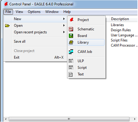
1)To create a new library go to the eagle control panel and select File->New->Library
1)To create a new library go to the eagle control panel and select File->New->Library
The Editing Window
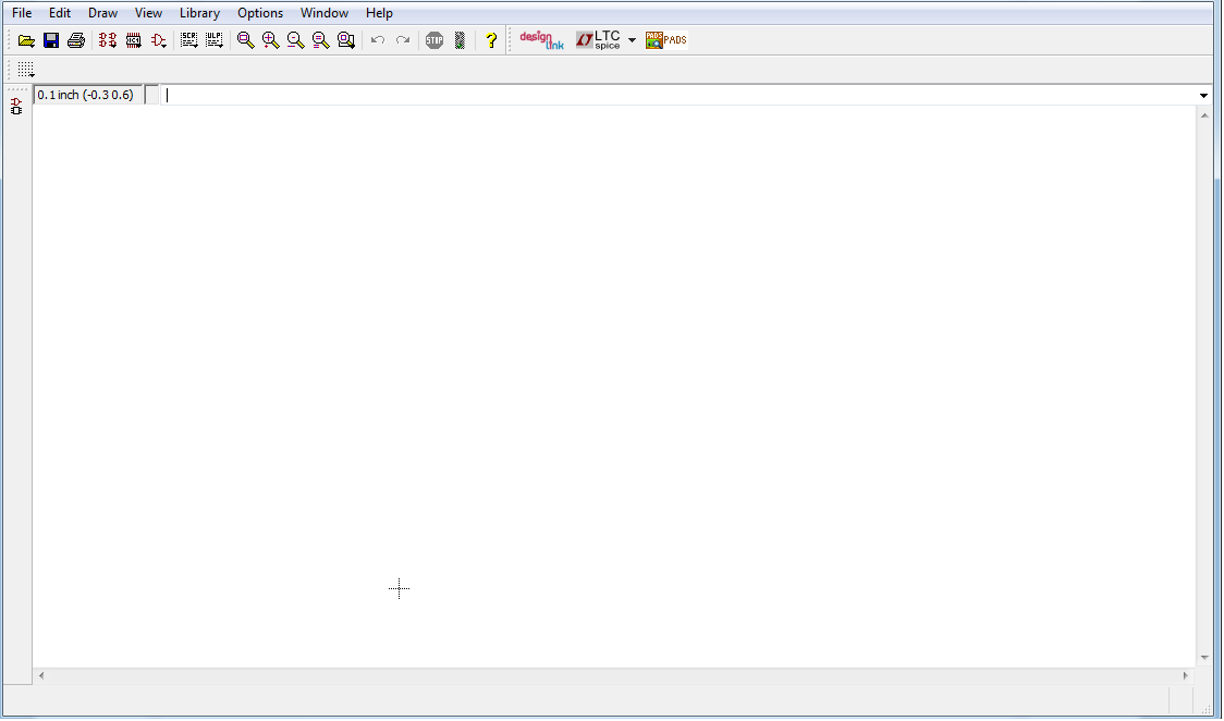
After creating a new library a screen similar to this should come up. It’s a good idea to save your library now. The name you pick for the save will remain the libraries name.
Creating the Symbol
There are three parts to each library part, the symbol, package, and device. We will start by making the symbol which is what will appear on the actual schematic of your circuit.
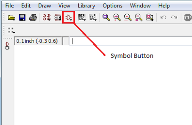
1) Create a new symbol by clicking on the symbol button ( the little and gate)
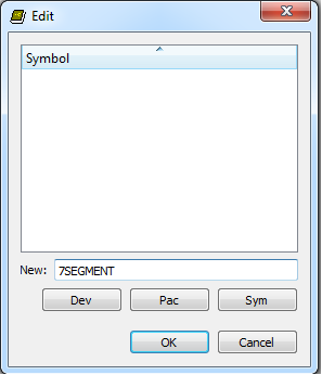
2) Type the name of your symbol in the NEW box and press ok, this is how it will show up in your library
1) Create a new symbol by clicking on the symbol button ( the little and gate)
2) Type the name of your symbol in the NEW box and press ok, this is how it will show up in your library
Creating the Symbol (continued)
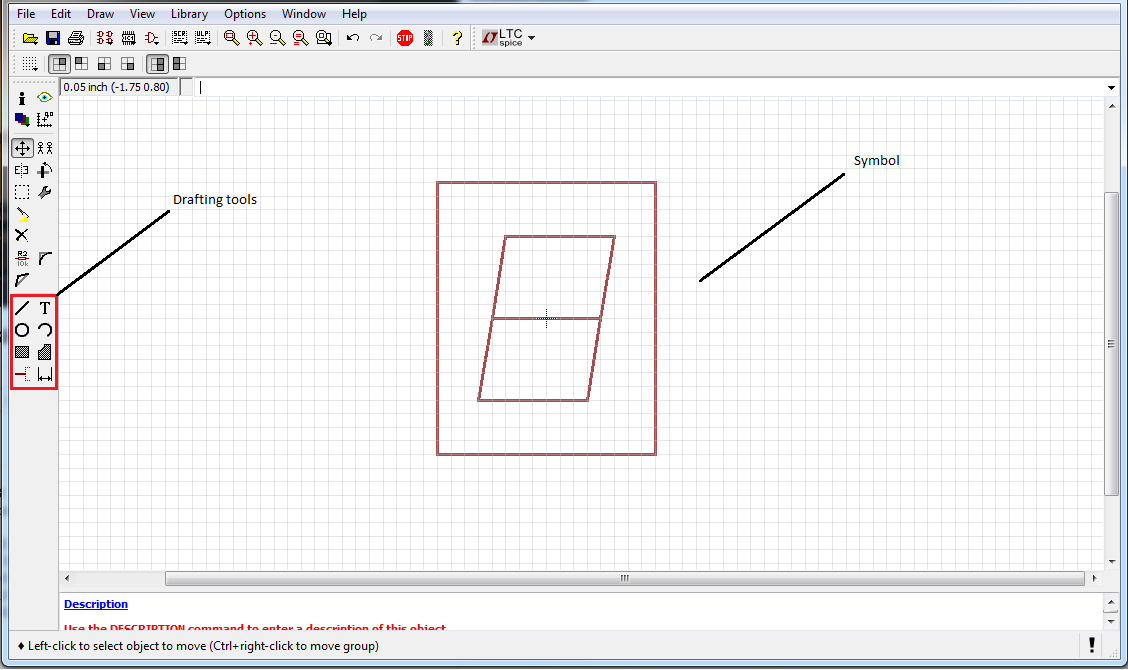
After you have made a new symbol you now have to draft the actual image of the part along with all the pins. It may help you to copy a similar parts symbol and editing it.
1) Select the wire tool to create the image of the symbol, you can also use the polygon tool and rectangle tool to aid you with this. make sure to align your part with the small cross in the drafting window, this is were you will have to click to move the actual part in the schematic editor.
1) Select the wire tool to create the image of the symbol, you can also use the polygon tool and rectangle tool to aid you with this. make sure to align your part with the small cross in the drafting window, this is were you will have to click to move the actual part in the schematic editor.
Adding Pins
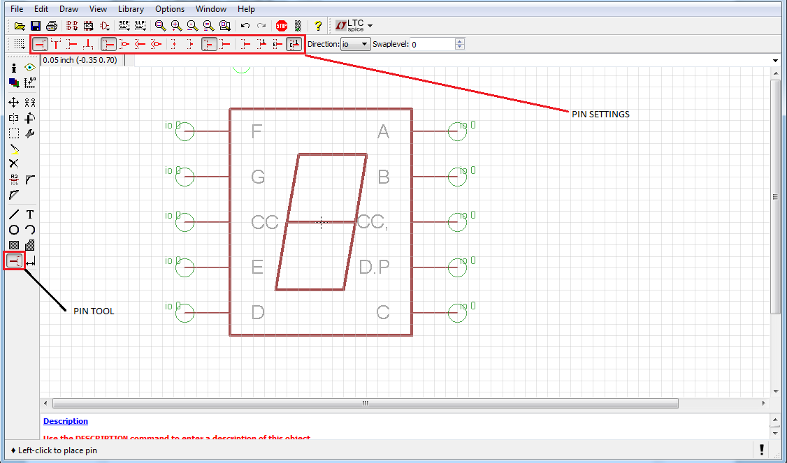
After you have come up with the basic outline of your part you now need to add pins to it. The pins are were you will create the actual connections in the schematic editor
1) first select the Pin tool and edit the settings to how long you want the pin, the properties of the pin, and its swap level (for basic parts set it to 0)
2) after selecting the pins place them on your symbol, after placing them you can edit their names by right clicking on them and selecting properties. the green circle is were the wire will connect to on the symbol
Adding Names and Values
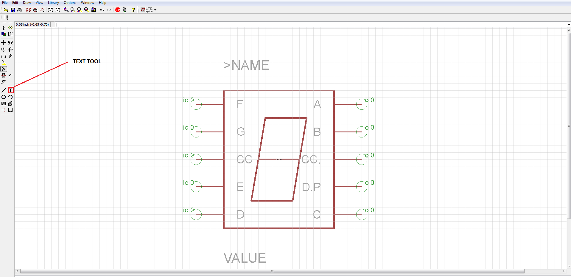
As you know, when you place a part down in the schematic editor it tells you the name of that part and the value you set it at, this does not come default for each part
1) select the text tool and type in >VALUE in all caps
2) set it to layer Values and place it below your part
2) do the same for the name but type in instead >NAME and set it to layer names
Congrats you are now done creating the symbol of your part, now we have to make the package
1) select the text tool and type in >VALUE in all caps
2) set it to layer Values and place it below your part
2) do the same for the name but type in instead >NAME and set it to layer names
Congrats you are now done creating the symbol of your part, now we have to make the package
The Package
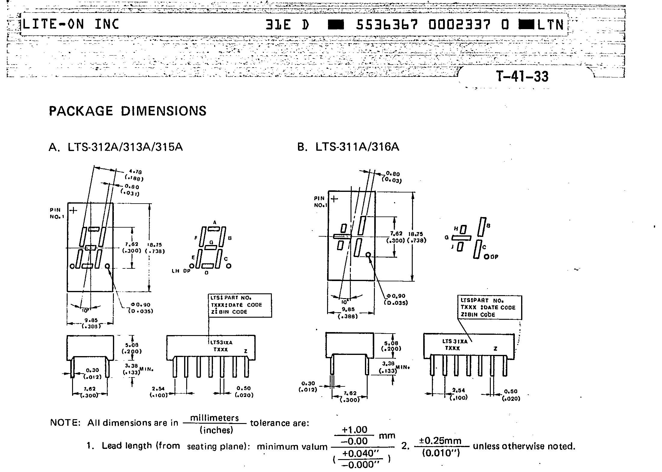
We will now move on to creating the Package of the actual part. It is critical that you do the package to the best of your ability because it is what goes on the completed board of your circuit. Luckily the datasheet gives you all the measurements of the part. For this tutorial I have been using a 7 segment display in this sheet. the sheet will look something like this.
Editing the Grid
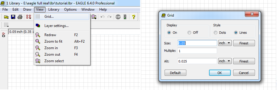
since we need to be really accurate with the placement of the package, we need to change the grid size so that it will be able to achieve the smallest spacing of the part.
1) go to View--> Grid, from here you can change the spacing of the grid to achieve smaller traces ( I usually set mine to .05 inches).
1) go to View--> Grid, from here you can change the spacing of the grid to achieve smaller traces ( I usually set mine to .05 inches).
Creating the Package
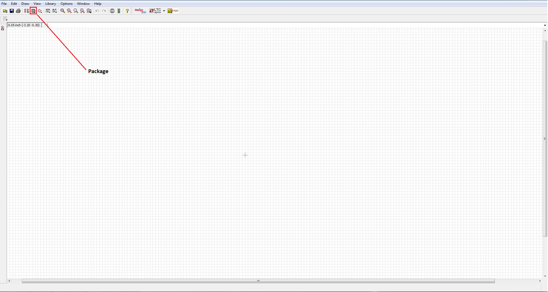
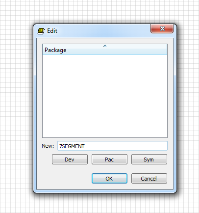
After you have set your grid and gotten your measurements you need to create your package. to create a package click the package button that is right next to the symbol button and create a new package the same way you created the symbol file.
Drafting the Package
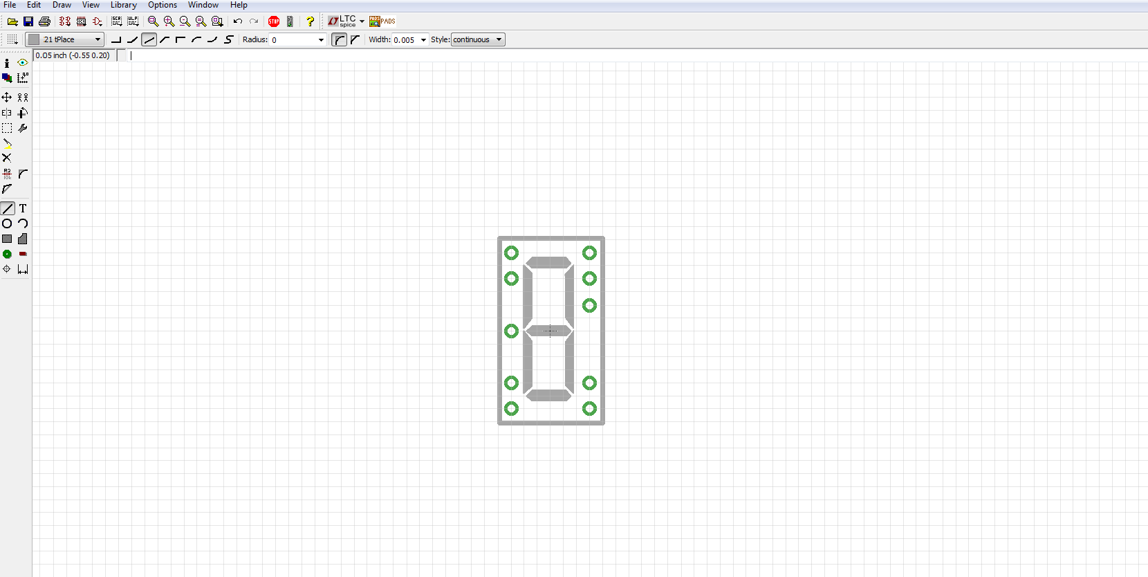
you draft the actual package in the same way you create the symbol. the only difference is that you have place the pads and smd pads a correct distance away from each other since this is what goes on the actual board
Create the Device
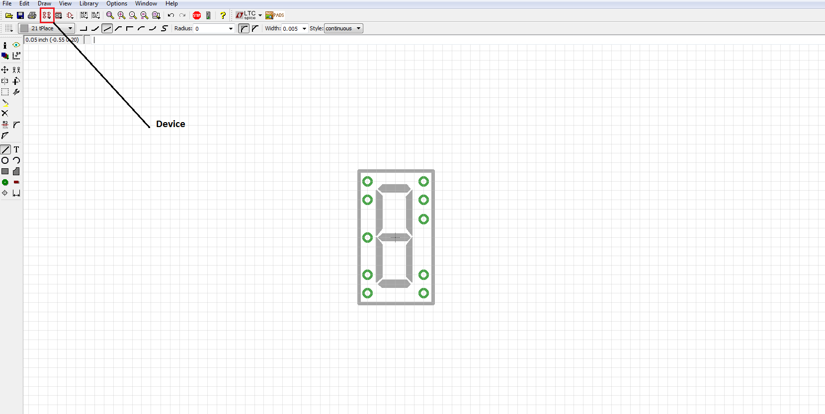
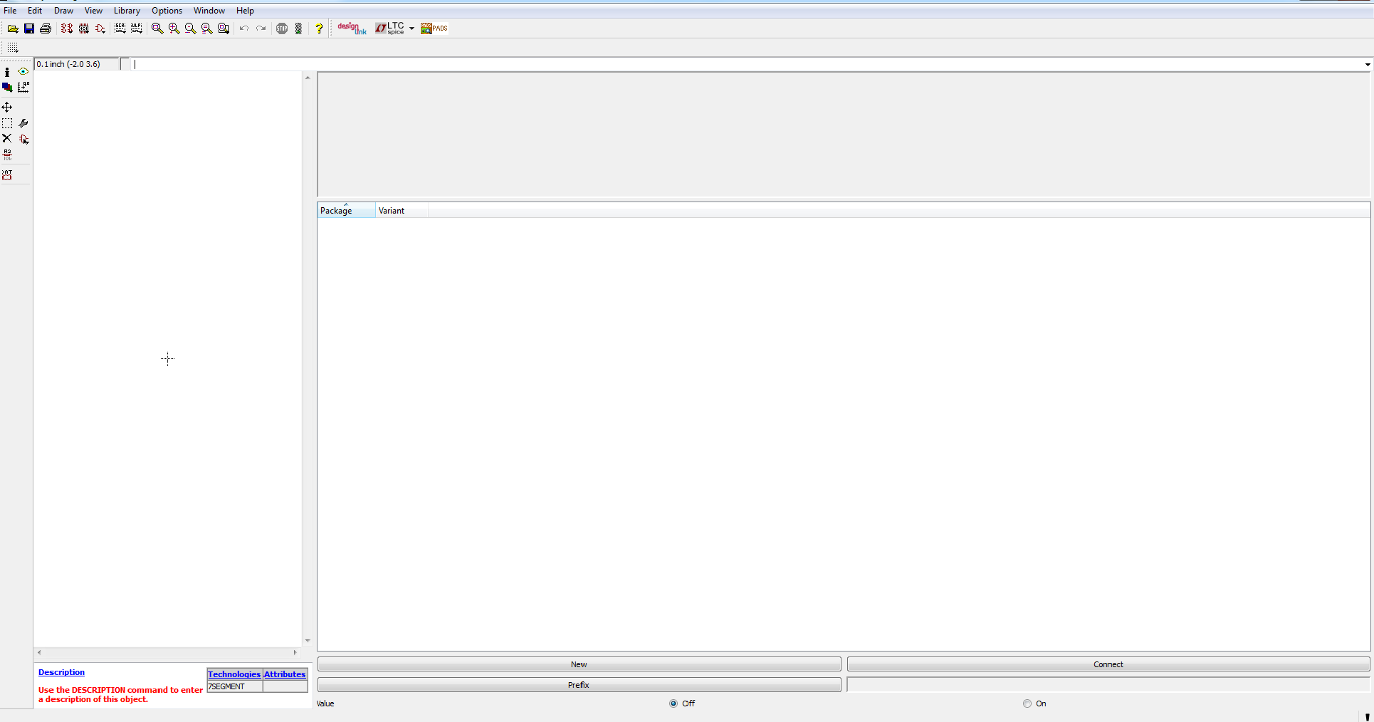
once your package and symbol is finished you are almost done. click on the device icon that's right next to the package icon and create a new device. a new window will now come up
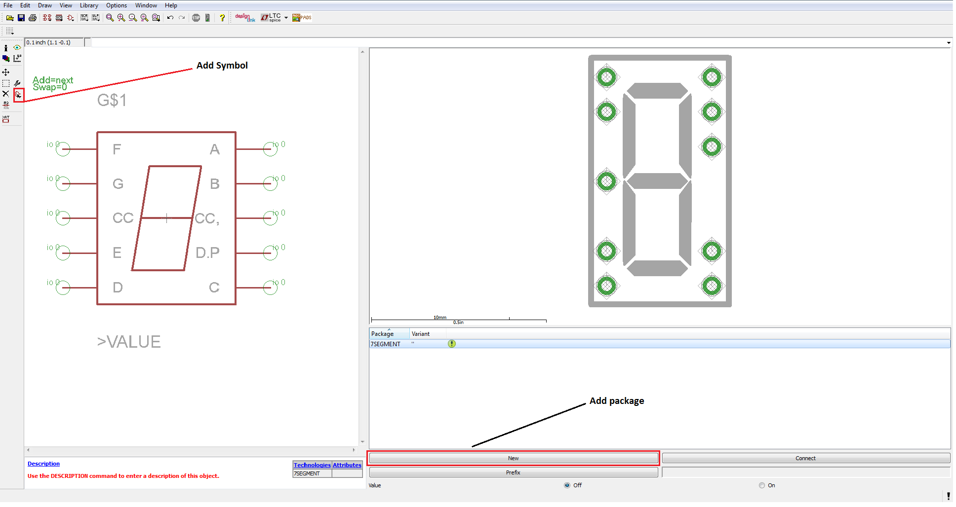
Click on the add icon and add your symbol to the box and then press the new button in the package window to load both your package and symbol for the device
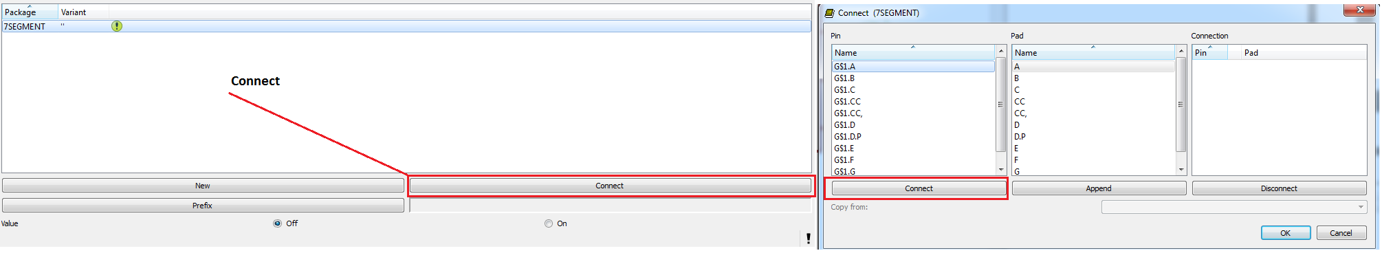
The last step is to connect your pins from the package to the pins on the symbol. click the connect button and then connect to connect the correct pins from the symbol to the package
YOUR DONE
CONGRATS! you are now done creating a new part for eagle. after saving you can pull up the library in the schematic editor like any other library