How to Make Bolt on SolidWorks in Three Minutes?
by ALAKBARI in Circuits > Tools
300457 Views, 34 Favorites, 0 Comments
How to Make Bolt on SolidWorks in Three Minutes?
Hi Everyone , Welcome to my tutorial on modeling a bolt in SolidWorks.
Have you ever used an SolidWorks software before? If not, it is totally fine. Hopefully after finishing my tutorial, you will have a sufficient knowledge about SolidWorks. I will try my best to help you learn more about SolidWorks. Let's start:
In this tutorial, you will design a bolt in SolidWorks.As you know bolts and screws are important little pieces that hold things from fall apart. Before being manufacture, Bolts are designed using any Auto Cad software. SolidWorks is the one that we are going to use in this tutorial.
Before going through the steps, there are things you need to know about SolidWorks:
1- SolidWorks is only available on Windows operating system.
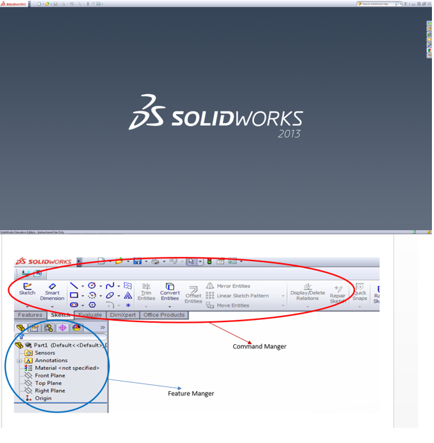
2- There are two important toolbar; one is the command manger and the other one is the feature manger, as shown in Figure 2.
The tutorial concludes nine steps and one optional step. It may take you from 5 to 15 min if you are a beginner, however, it can last for 3 minutes if you are professional on SolidWorks.
Don't forget " practice makes perfect"
Create a Document
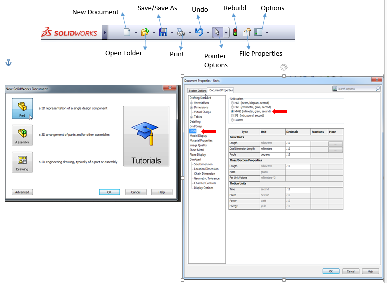
1. Once you open SolidWorks, go to upper left corner and click the sheet of paper to create a new document .(Refer to Figure 1)
2. Click on Part then OK (Figure 2.)
3. In our design we are going to use MM-GS unit system, so in order to do that; select options icons on the toolbar (Figure1.)
4. Click on Document Properties tab . (Figure 3)
5. In the left menu, select “Units”. ( figure 3)
6. In the unit system bar, choose “MMGS”. ( figure 3)
7. Click OK
Sketch the Head of the Bolt
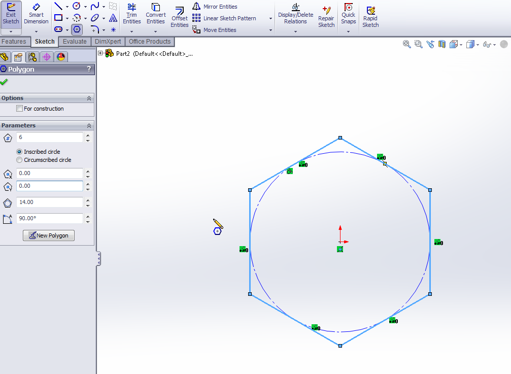
1. On Feature manger, right click your mouse on "Right Plane" and then select Sketch.
2. At this point a blue square and two red arrows will appears, go to the command manger under sketch choose "Polygon" shape.
3. Sketch the polygon from the beginning of the two red arrows. To complete this step you need to see an orange circle on the two red arrows. It means you are drawing from the origin.
4. From the origin, go straight up to 14 mm. Don’t worry if you don’t get it to the specific size you can modify it later.
5. To modify the measurement of your Polygon, you will see a Polygon feature on the left. On Polygon Feature under parameter, write on the forth white rectangular 14 mm, which is the radius of the circle.
Attention!! When you set the radius to 14 mm, your drawing may seem small. Press (f) to fit the drawing to your screen.
after doing all the steps above, your sketch should look as the picture.
Extrude Boss/Base the Polygon
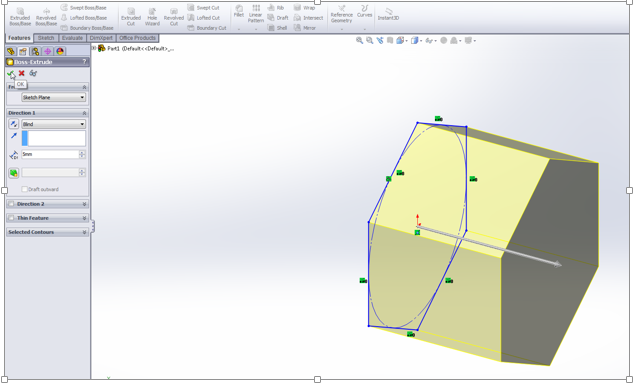
1. To extrude the polygon, go to feature on the command feature toolbar.
2. Select Extrude Boss/Base.
3. On the left is the Boss-Extrude menu, Set the depth to 5 mm.
4. Ok. (Figure 1)
2. Select Extrude Boss/Base.
3. On the left is the Boss-Extrude menu, Set the depth to 5 mm.
4. Ok. (Figure 1)
Rounding the Head
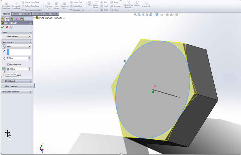
To round the head of the bolt :
1. Select one side of the head.
2. Draw a circle. Go to sketch on the command feature, then choose circle.
3. Set the radius of the circle to 7 mm.
4. Go to feature, then click on Extrude Cut .
5. Under direction 1 on the Cut-Extrude feature, Set the depth of the cut to 1 mm.
6. Select Flip Side to Cut.
7. Press the icon and set the degree to 60.
8. Click on the check mark.
So far you are doing well. You have completed the head of the bolt.
Remember "the journey of 1000 mile start with a step."
Create the Shaft
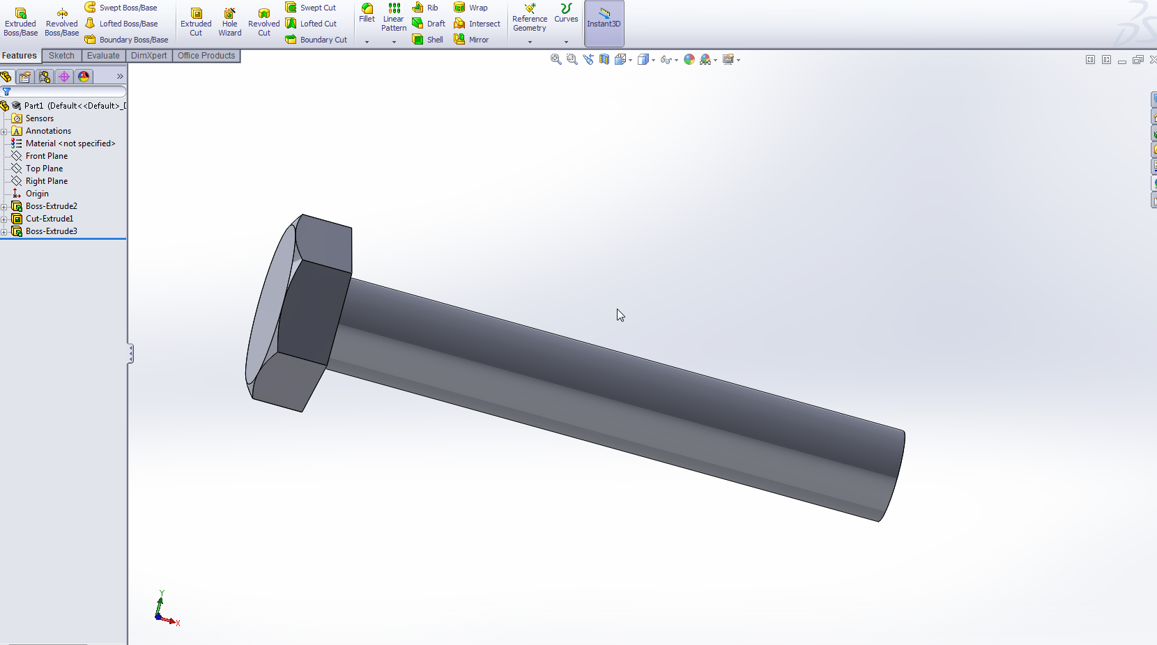
1. Sketch a circle on the other side of the head with a radius of 4 mm, then click OK.
2. On Feature, click on Extrude Cut.
3. Set the depth of the cut to be 50 mm, then press OK.
After finishing this step, your bolt should look same as the picture shown above.
2. On Feature, click on Extrude Cut.
3. Set the depth of the cut to be 50 mm, then press OK.
After finishing this step, your bolt should look same as the picture shown above.
Chamfer the End of the Shaft
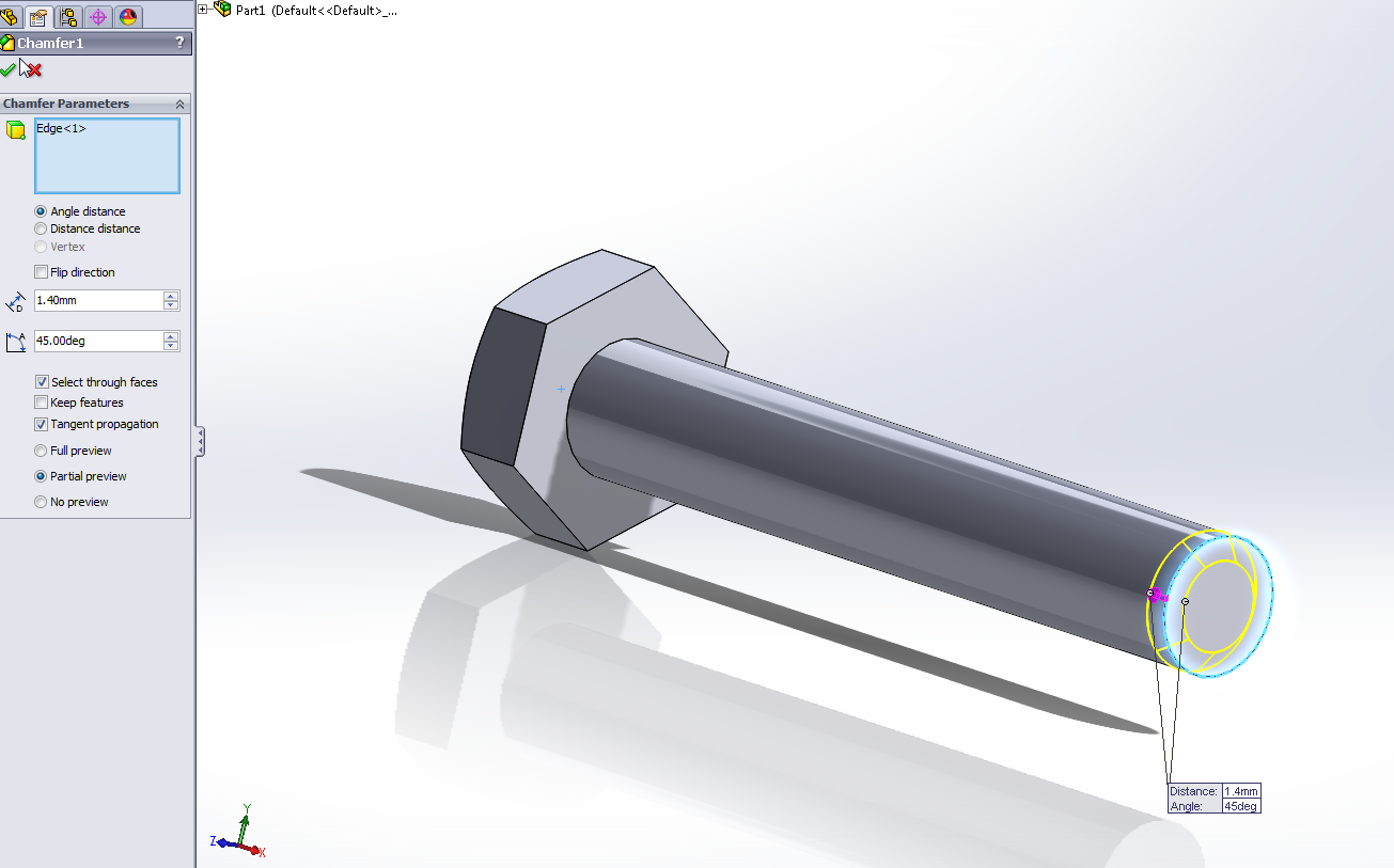
1. Go to Feature on the command manger and select the arrow on Fillet and choose Chamfer.
2. Select the edge at the end of the shaft. On the Chamfer window at the left, under chamfer parameter, you should see "Edge<1>" on the white square.
3. Set the depth of the chamfer to be 1.40 mm at 45 degree.
4. Click OK.
Reminder usually after each steps, you should click ctrl+s to save what you have done.
Make the Thread of the Bolt
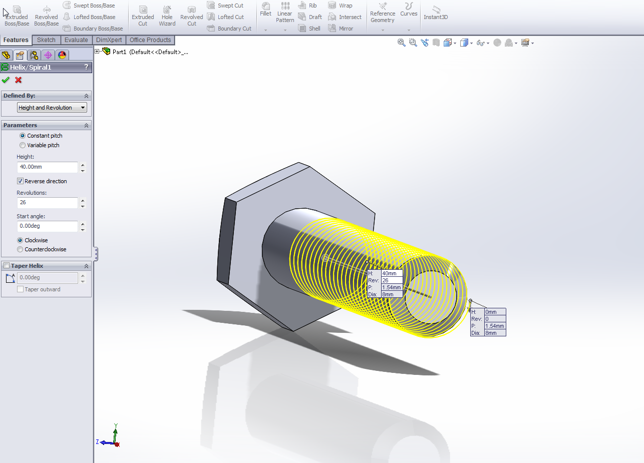
1. At the end of the shaft, Select the circle.
2. Starting from the origin (center), sketch a circle with a radius of 4 mm.
3. Click OK.
4. At top left corner, click on Feature, then choose Curve>Helix and Spiral.
5. On the Helix window feature, define the helix by Height and Revolution.
6. Under Parameters, set the height to be 40 mm.
7. Select reverse direction.
8. Set the number of revolutions to 26.
9.Set the starting angle is at zero degree.
10. Click OK.
Drawing the Shape of the Thread
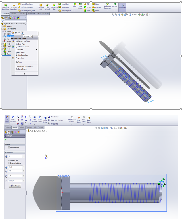
1. At the left on the features manger, right click on the "Top Plane" and choose "Normal To ". (Figure 1.)
2. At far right in the beginning of the helix line, sketch a Polygon with three number of sides ( Figure2.)
3. In order to do that, type 3 on the first rectangular of the Polygon feature.
4. Also, set the inner circle to be 1.40 mm.
5. Finally, set the angle at 270 degree.
6. Click OK.
7. Click on Sketch at the upper left corner of your screen.
Finishing the Thread
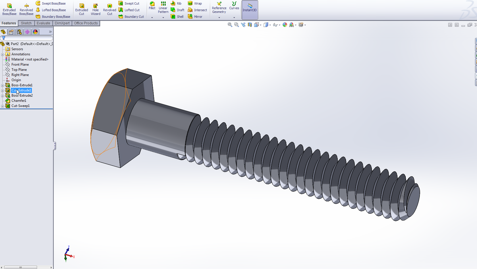
This is your last step. Never give up, you are one step from your first experience with SolidWorks.
1. Go to Features and click on Sweep Cut.
2. Under Cut-Sweep Feature, check Profile sweep.
3. On the drawing, First select the Polygon.
4. Next, choose the helix.
5. Click OK.
6. Click anywhere on the screen to get rid of the Polygon( triangle).
Congratulation, you are officially completed the tutorial at this point. I hope you have enjoyed my tutorial and hopefully my instructions were clear to you. Your bolt should look similar to the picture shown above.
I have uploaded two videos trial in case you face any struggle on one of the steps. One of them is mine and the other one is from a user on YouTube.
User from YouTube:
http://www.youtube.com/watch?v=T_K79NHf9Gg
My video:
http://www.youtube.com/watch?v=yGX5RJkS-Dk
My video:
http://www.youtube.com/watch?v=yGX5RJkS-Dk
Optional : Change the Color of the Bolt
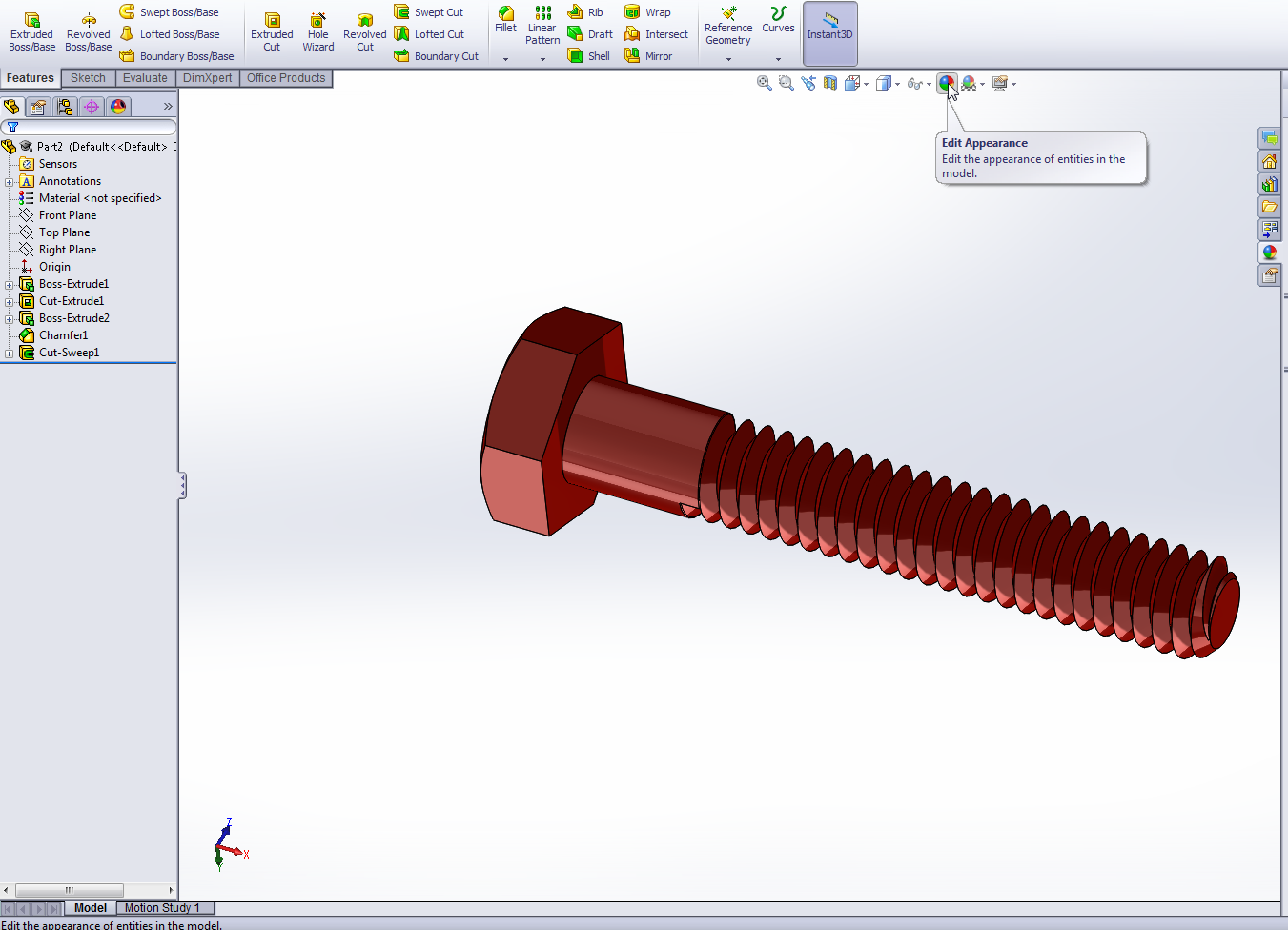
To change the color of the bolt:
1. In the upper middle of the drawing screen there are several icons, select the on says " Edit Appearance" (Figure1)
2. Choose any color you like then click OK.
1. In the upper middle of the drawing screen there are several icons, select the on says " Edit Appearance" (Figure1)
2. Choose any color you like then click OK.