How to Make a Tesseract in Sketchup
by Pickles5000 in Workshop > 3D Printing
6870 Views, 5 Favorites, 0 Comments
How to Make a Tesseract in Sketchup
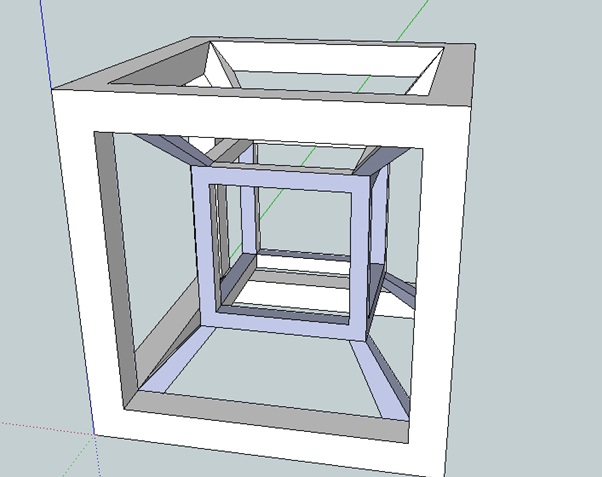
This instructable will show you how to design a Tesseract in Sketchup. A Tesseract is '...the four-dimensional analog of the cube...'. (From http://en.wikipedia.org/wiki/Tesseract). To complete this instructable, you will need a basic - moderate knowledge of how to use Sketchup.
You Will Need
For this instructable, you will need:
1. A computer with the following specifications: http://support.google.com/sketchup/bin/answer.py?hl=en&answer=36208
2. Sketchup installed on the above computer. If you don't know how to install software then maybe try an easier instructable. If you don't have Sketchup installed then look here: http://www.sketchup.com/intl/en/download/
3. 30 minutes to 1 and a half hours depending on you previous knowledge of Sketchup and how quickly you work. (The first time took me about 2 hours to work out where I was going to start and the best way to construct it).
4. A mouse. Trust me - invaluable.
Open Sketchup

Unless you have disabled it,, when you first open Sketchup you will see the 'splash screen'. The first thing you want to do is set the template. As I'm Australian, I prefer to use metric (millimetres) unless I'm working on a bigger project like furniture. (6 feet seems easier to visualise than 182.88 cm). I find that apart from the units, it doesn't really matter which template you use (also, if you choose inches and want to input a value in millimetres, all you have to do is add the desired suffix to the value and Sketchup will automatically change it for you). However for perfection's sake we will choose Product Design and Woodworking. If this step is too complicated for you, I suggest using a search engine (please tell me you know how) to find some easier tutorials to start off with).
Starting the Model
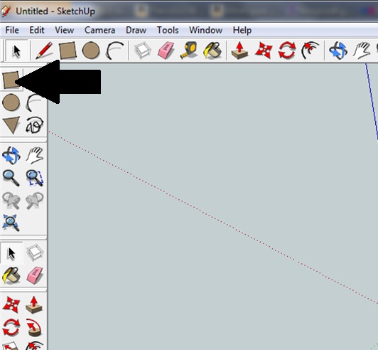
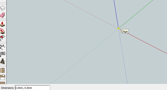
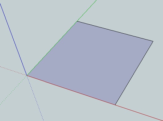
Follow the text and look at the picture if something is not clear:
Firstly, once the 'creation window' has opened, click on the Rectangle/Square tool.
Click on the Origin with the rectangle tool selected.
Use the rectangle tool to create a square 50mm by 50mm.
Firstly, once the 'creation window' has opened, click on the Rectangle/Square tool.
Click on the Origin with the rectangle tool selected.
Use the rectangle tool to create a square 50mm by 50mm.
Construct the 'Wireframe'
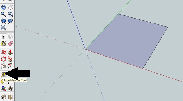
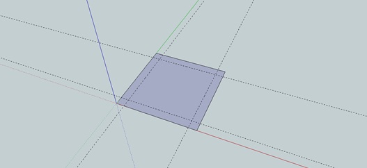
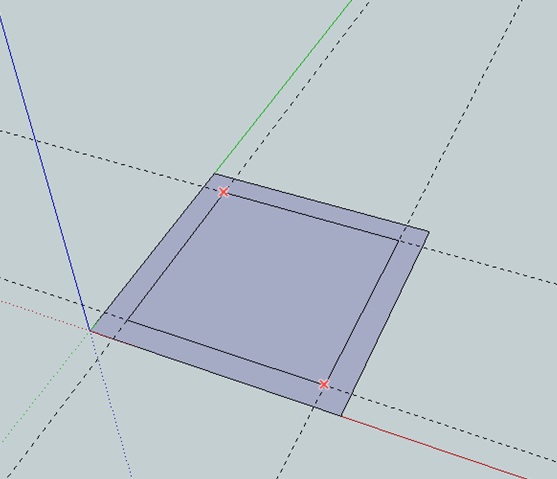
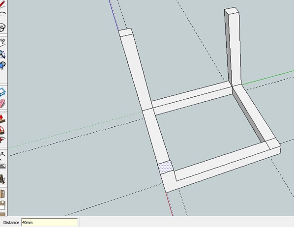
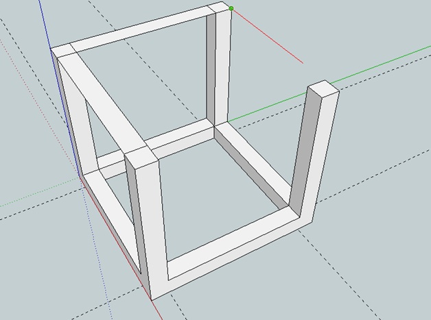
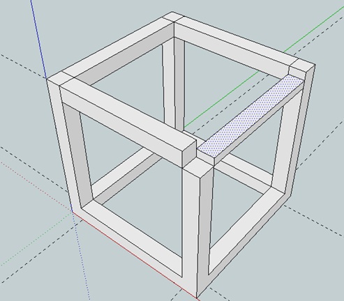
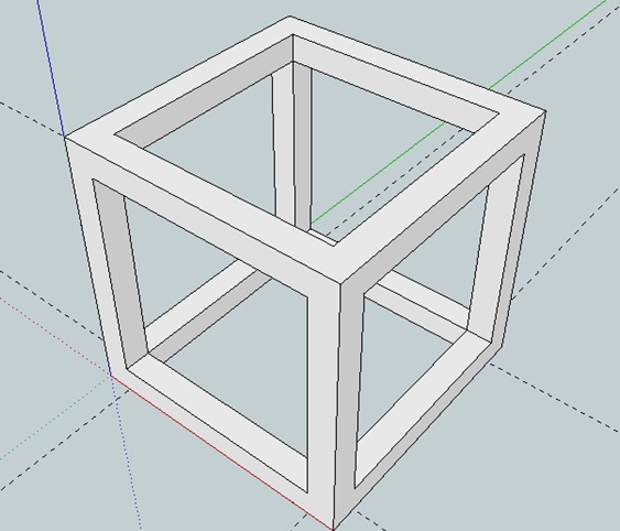
Using the tape measure tool, create guides 5mm into the square on all four sides.
Use the Rectangle tool to go over the 40mm by 40mm square traced by the guides.
Delete the internal square and then use the extrude tool to raise the remaining shape up 5mm.
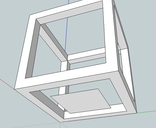
Outline each 'leg' (as seen in the picture) and extrude each one up 40 mm.
Use the line tool to connect the legs at the top. You will probably have to delete some extra faces that are automatically created so that you just have the 'wire frame'.
Extrude the top parts up 5mm - see image.
Delete unnecessary lines around latest extruded [arts and your model should now look like the final image for this step.
Construct the Internal Cube
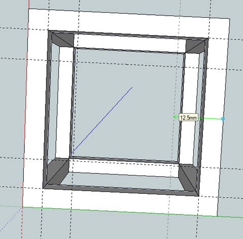
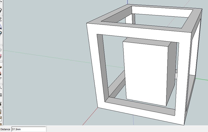
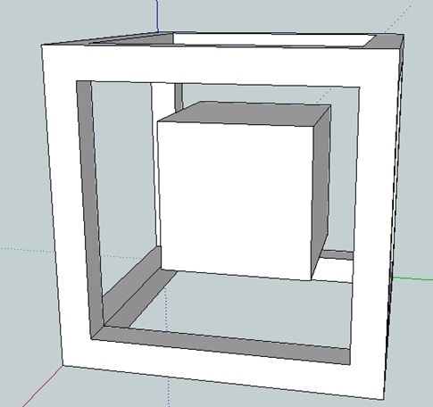
Use the tape measure tool to create guides 12.5mm in from each of the outer base sides of the outer cube.
Use the Rectangle tool to go over the 25mm by 25mm square created by the guides, then delete the guides.
Extrude the square up 37.5mm.
Extrude the Bottom of the now rectangular prism up 12.5mm. You should now have a 25x25x25mm cube.
Use the Rectangle tool to go over the 25mm by 25mm square created by the guides, then delete the guides.
Extrude the square up 37.5mm.
Extrude the Bottom of the now rectangular prism up 12.5mm. You should now have a 25x25x25mm cube.
Construct Ineternal 'Wireframe'
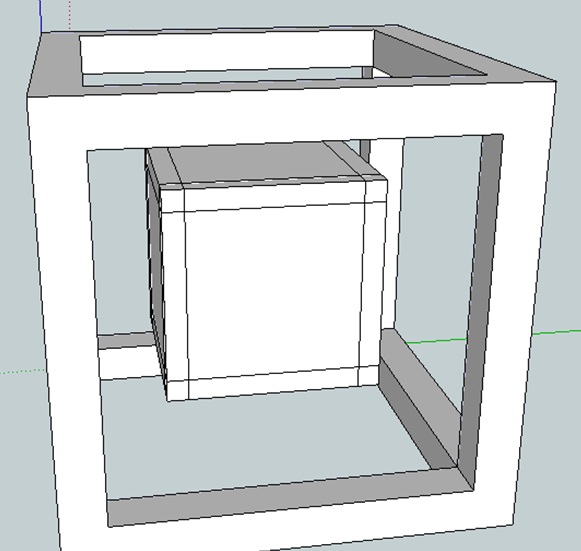
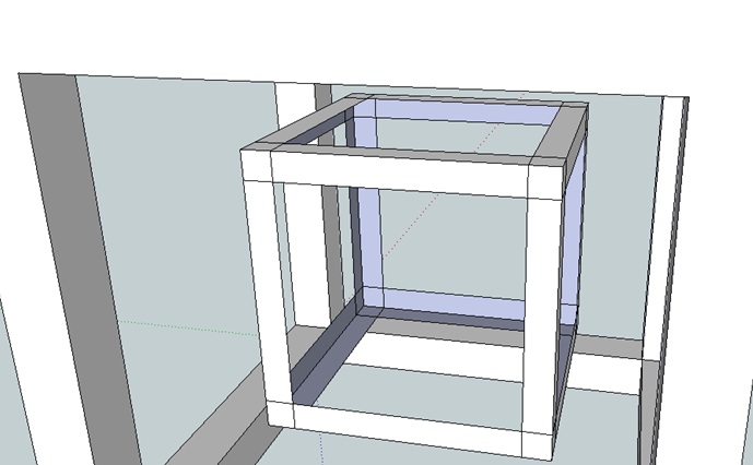
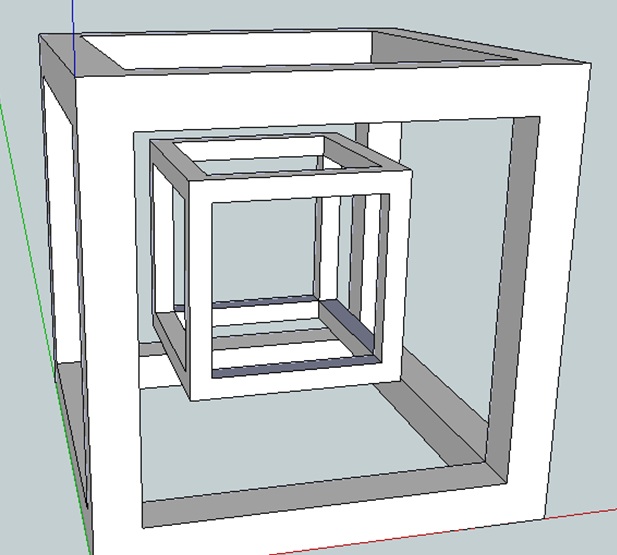
Using your preferred method (I use a combination of tape measure tool and line tool - you should know by now what works bet for you) outline a 2.5 mm wire frame on the internal cube - see image.
Delete the extra faces of the internal cube to create a 'wire frame' outline.
Finish the internal wire frame using your preferred method to make each 'leg' 3d. See image for finished internal wire frame.
Delete the extra faces of the internal cube to create a 'wire frame' outline.
Finish the internal wire frame using your preferred method to make each 'leg' 3d. See image for finished internal wire frame.
Connect the Cubes and Finish Your Tesseract
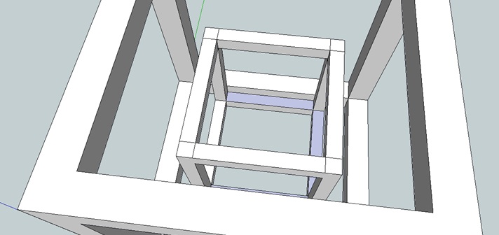
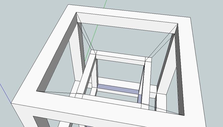
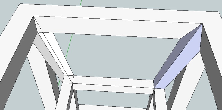
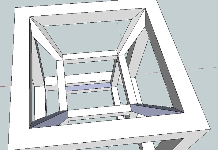
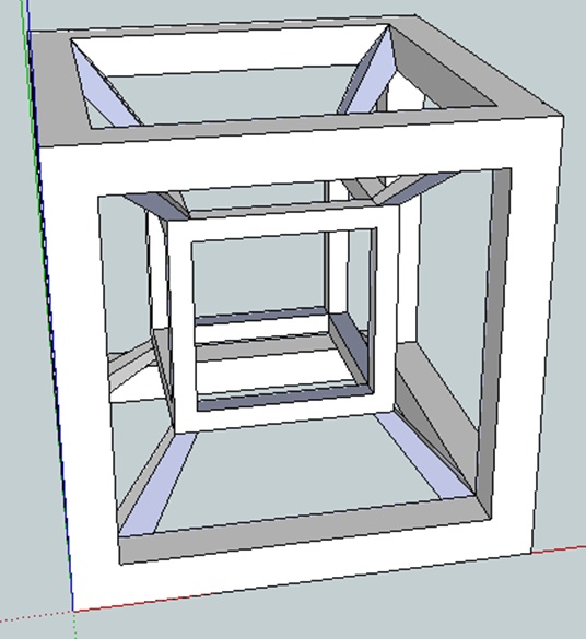
The next step is to connect the two wire frame cubes to each other. To do this I used the line tool but you may want to use another method depending on how you want to connect them.
Firstly, on he top 'face' of the internal cube, outline the legs - see image.
Use the line tool to connect the outer corner of the internal cube to the corresponding outer corner of the outer cube. Do the same for internal corners.
Finish the connection as shown in the image.
Repeat above steps for bottom of internal cube.
If you have a 3d printer you can now print your model. (You may have to export it to a different format). Alternatively, you can use a service like Shapeways to print the model.