Platonic Solid Bike Light Fixture
by BradNiedt in Outside > Bikes
5804 Views, 31 Favorites, 0 Comments
Platonic Solid Bike Light Fixture
.jpeg)
.jpeg)
.jpg)
.jpeg)
.jpeg)
.jpeg)
.jpeg)
.jpeg)
.jpeg)
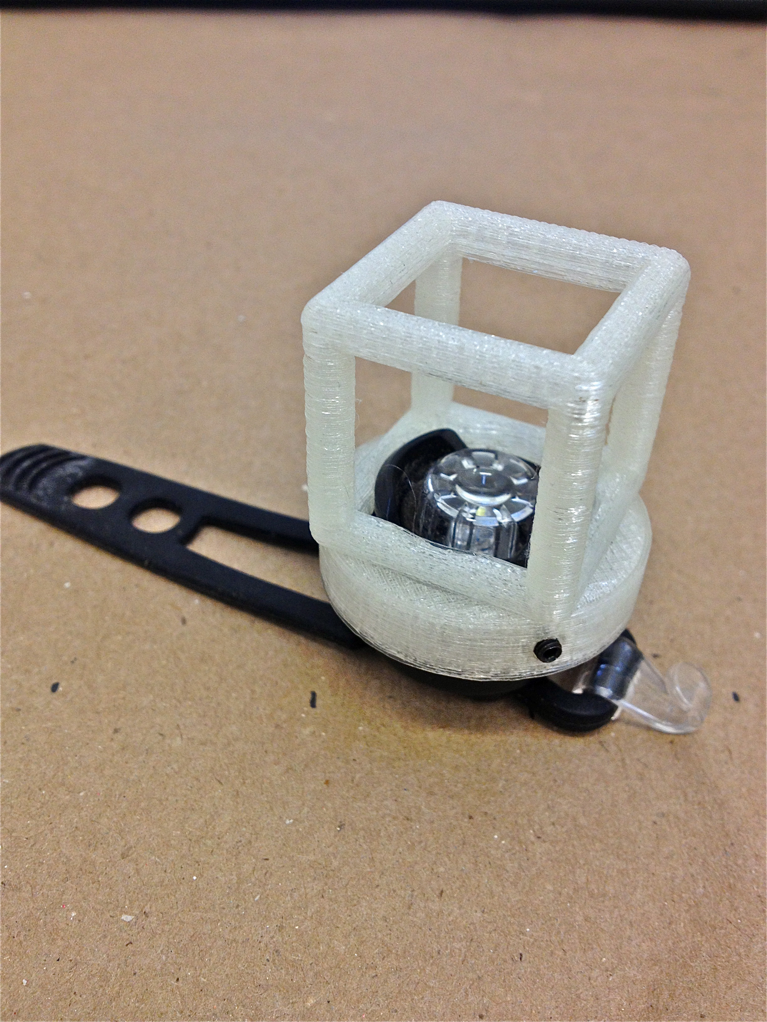
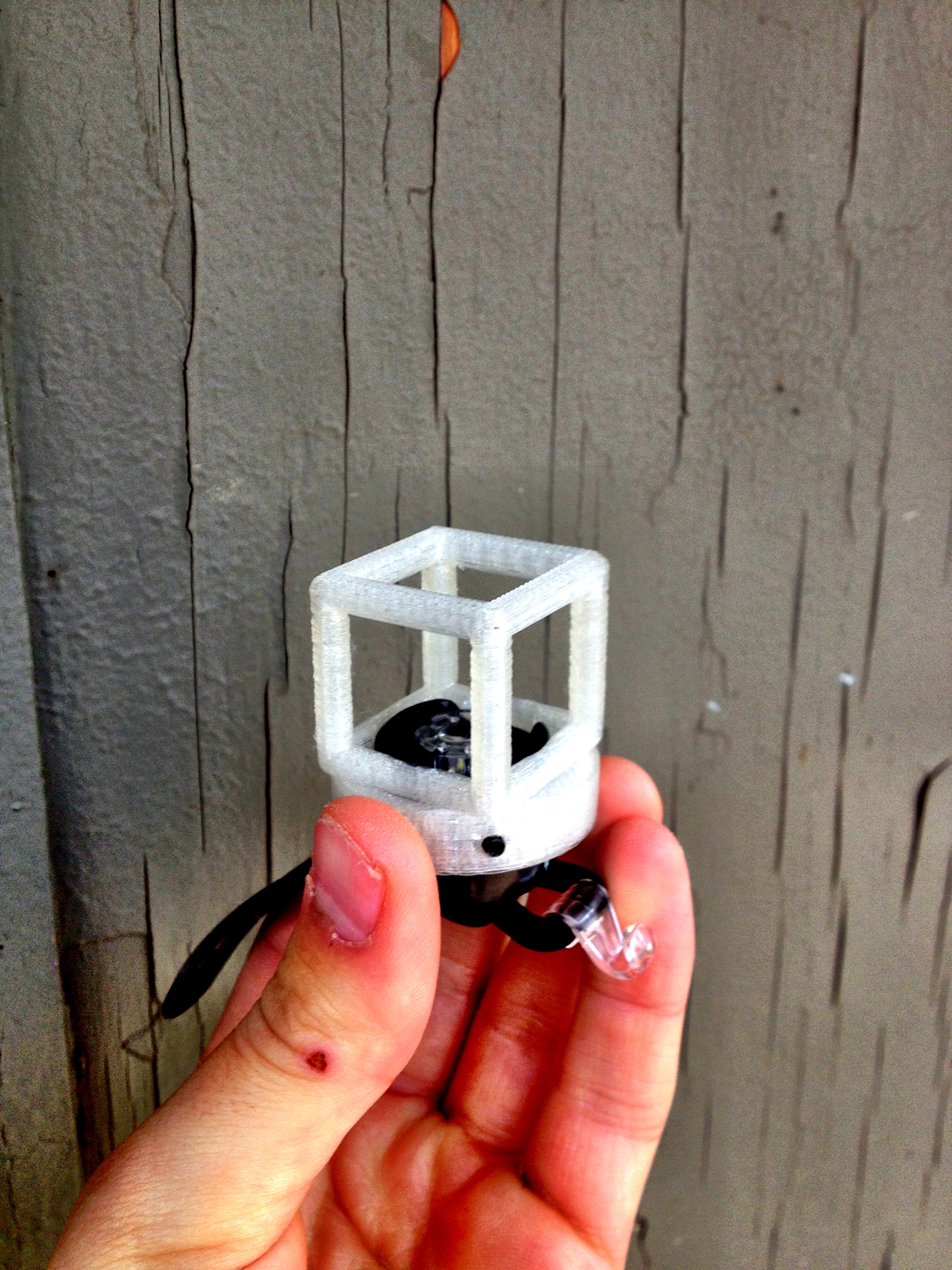
This instructable will show you how to make a platonic solid bike light fixture for a Bontrager "Glo" bike light.
This project began as a way to meld my passion for biking, geometry, and art. I remixed a platonic solid design created by WilliamAAdams from thingiverse to create the fixtures.
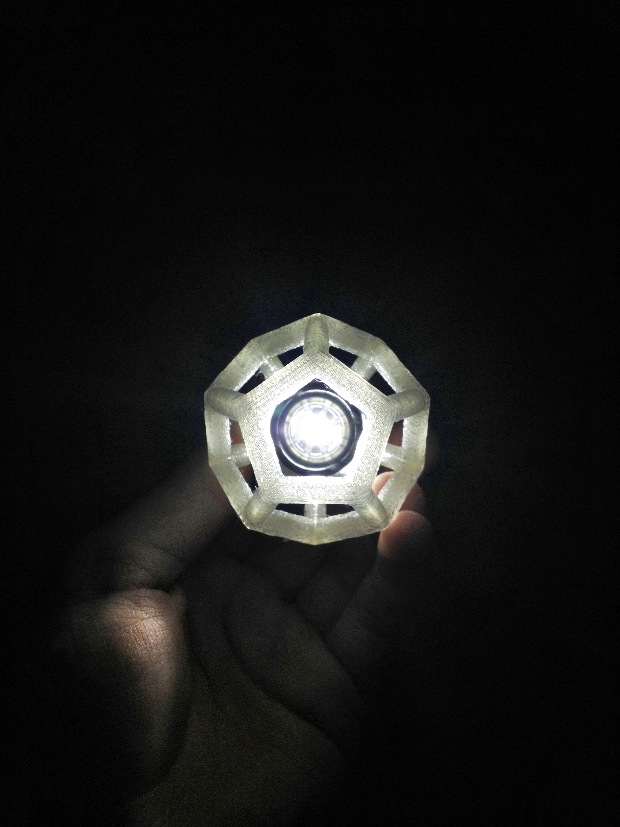
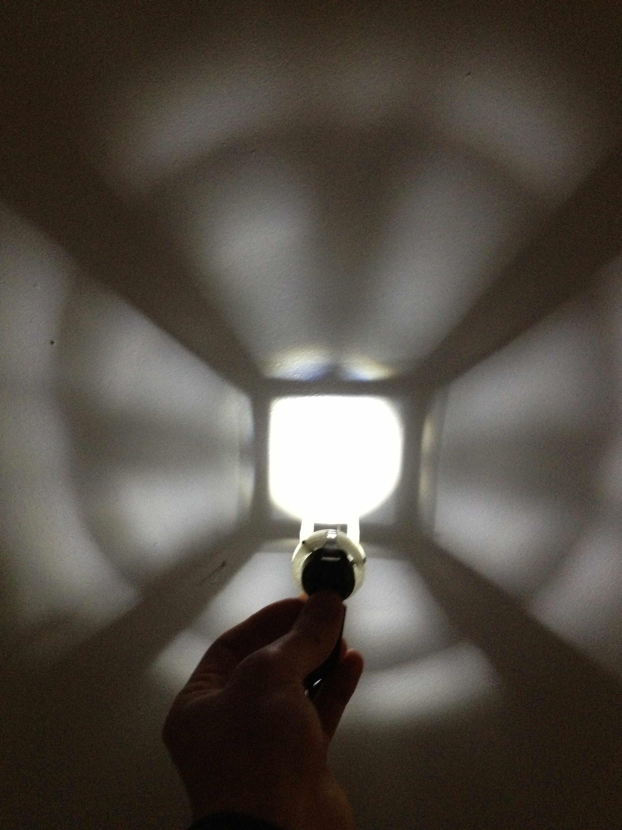
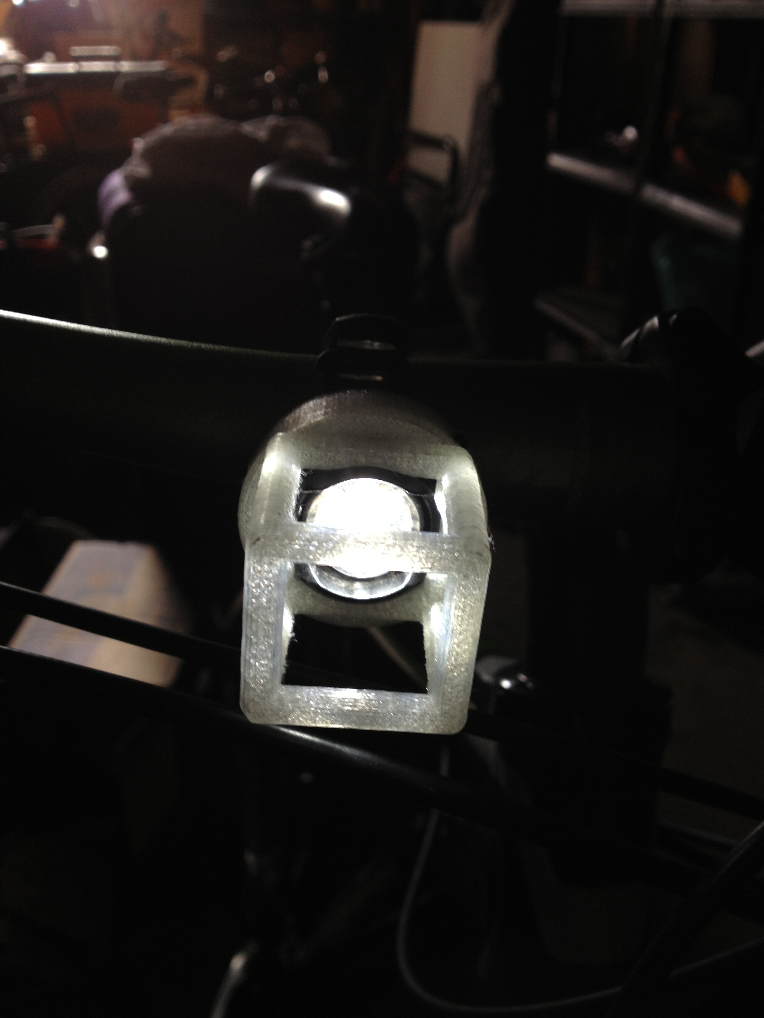
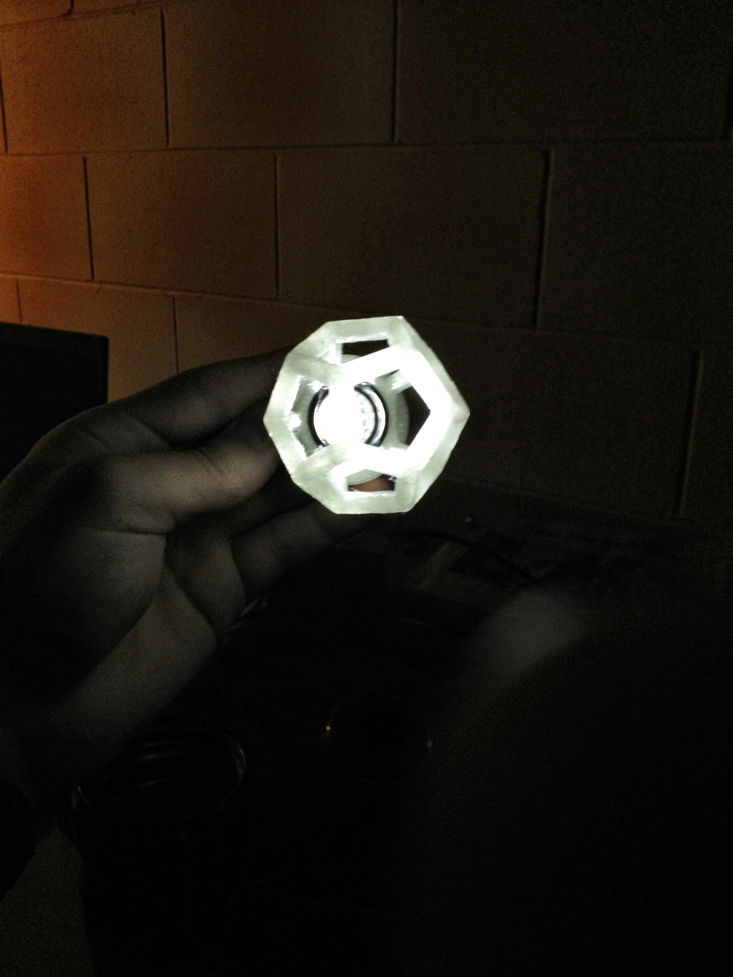
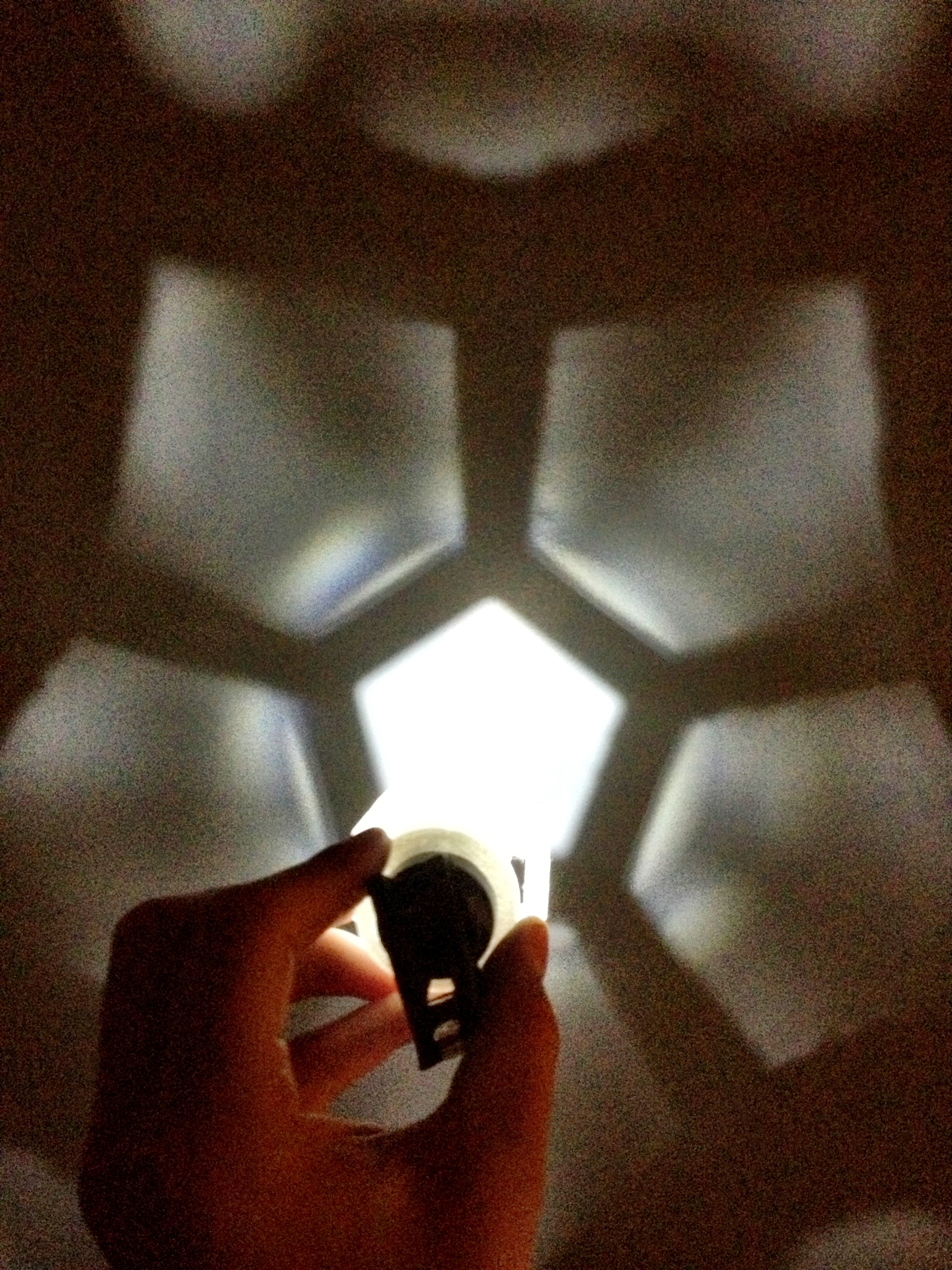
The light will now light the road (creating a geometric shadow of the platonic solid in the light), make the fixture glow(making the rider/bike more visible), and it will look cool(c'mon, platonic solids are AWESOME).
This is a remix of WilliamAAdams' thingiverse- full credit is given to WilliamAAdams for his platonic solid design that I remixed.
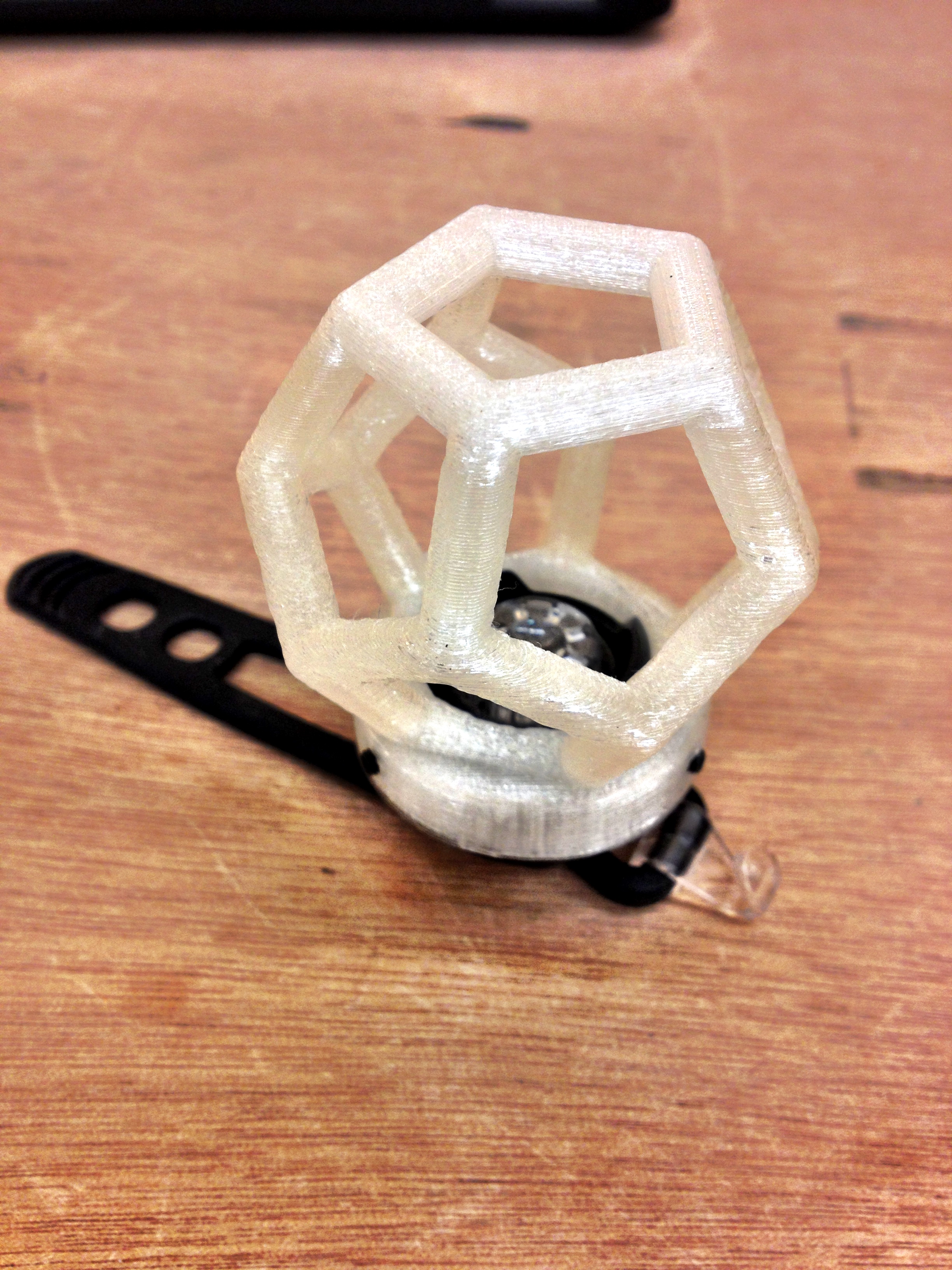
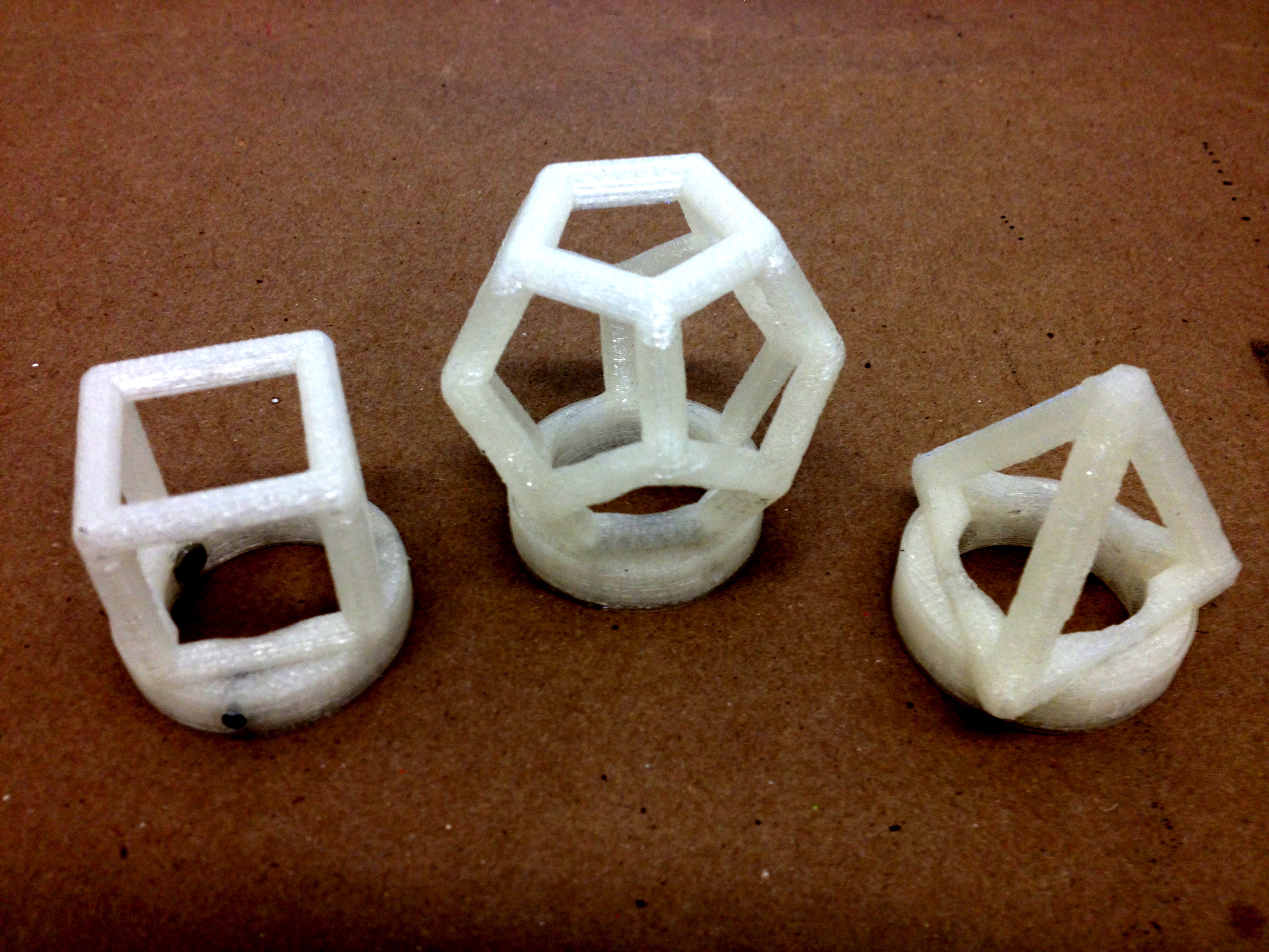
For this instructable, I will show you how to create a fixture with a hexahedron, but you can use these same steps to do the Dodecahedron or tetrahedron designs from WilliamAAdams to create a set of fixtures for the bike light. I've included a few photos of the other platonic solids I remixed as well.
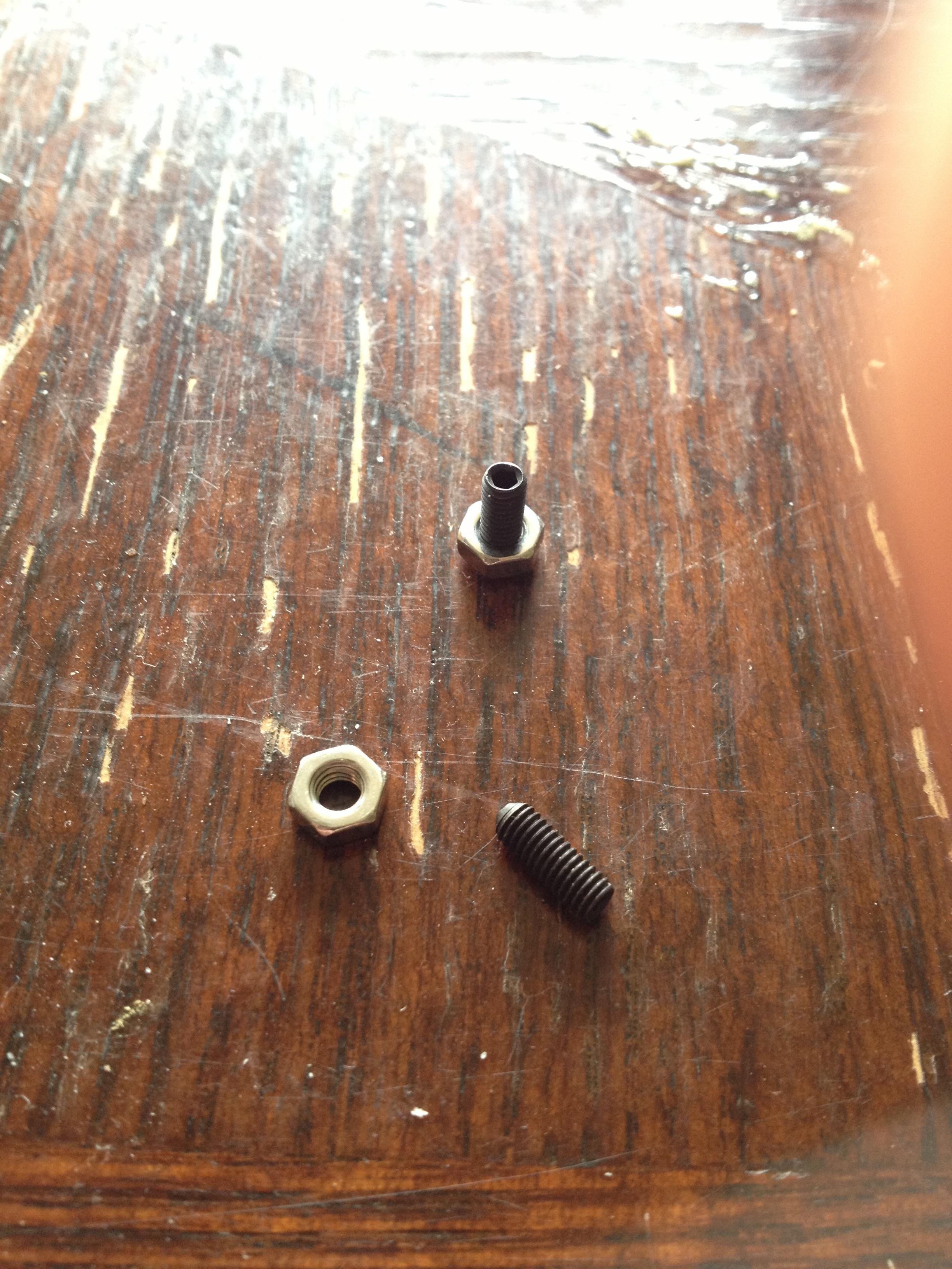
You will need to have experience with Rhino CAD program, M3 allen set screws and nuts, a Bontrager Glo bike light, and some sort of access to a 3D printer with clear plastic.
You can find the bike light here: http://bontrager.com/model/11364
The nuts and screws can be found at Ace Hardware or Home Depot.
Full recognition is given to WilliamAAdams for his Platonic Solids for OpenSCAD 2.0 design!
Download the Platonic Solid .stl File From Thingiverse
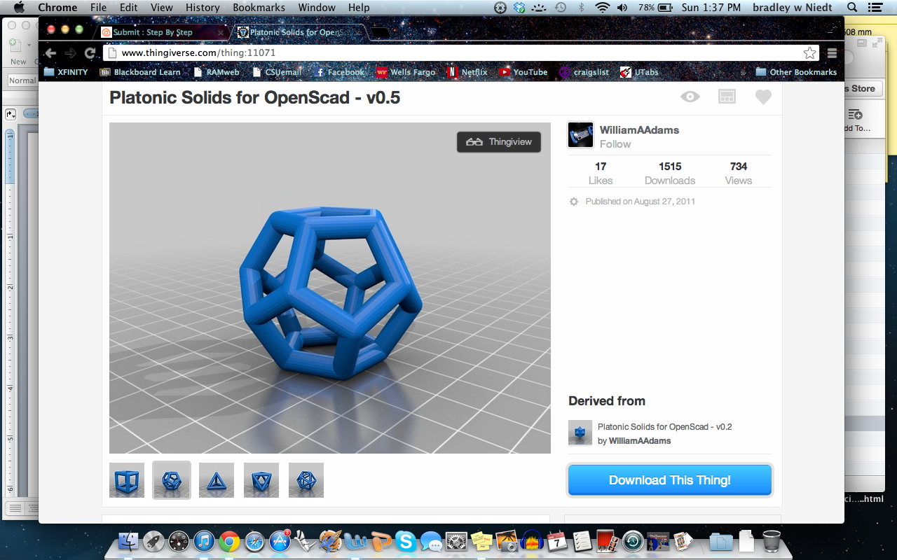
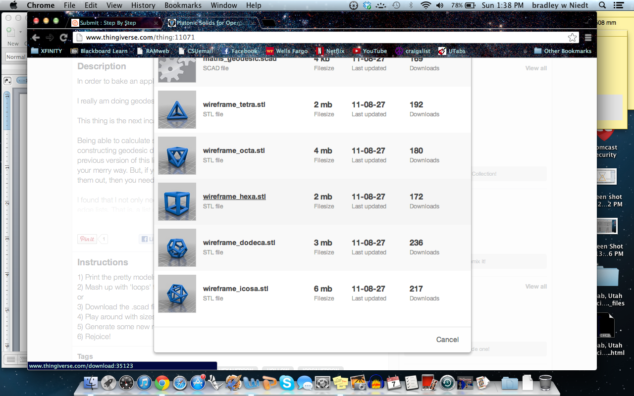
First, get on your web browser, and go to www.thingiverse.com.
Next, search “Platonic Solids”, and click on the third option, labeled, “Platonic solids for OpenScad- v.0.5 by WilliamAAdams”.
Click on the link labeled, “Download This Thing!”, and download the platonic solid of your choice. As I said earlier, in this instructable I will highight how to make a hexahedron bike light fixture.
Next, open Rhinoceros CAD program, and open the .stl file you just downloaded.
Fitment Disc
Here’s where things get rigid- you must follow these directions EXACTLY in order for the apparatus to fit onto this specific bike light.
First, we must create the fitment disc that will enable the apparatus to be mounted on the bike light.
open rhinoceros CAD program.
Make sure your units are set in millimeters, as this will be the units that the platonic solid file will open as, and the measurements for this instructable will need to be followed STRICTLY.
Designing the Fitment Disc
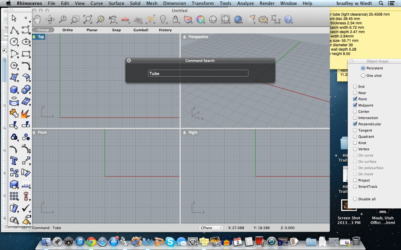
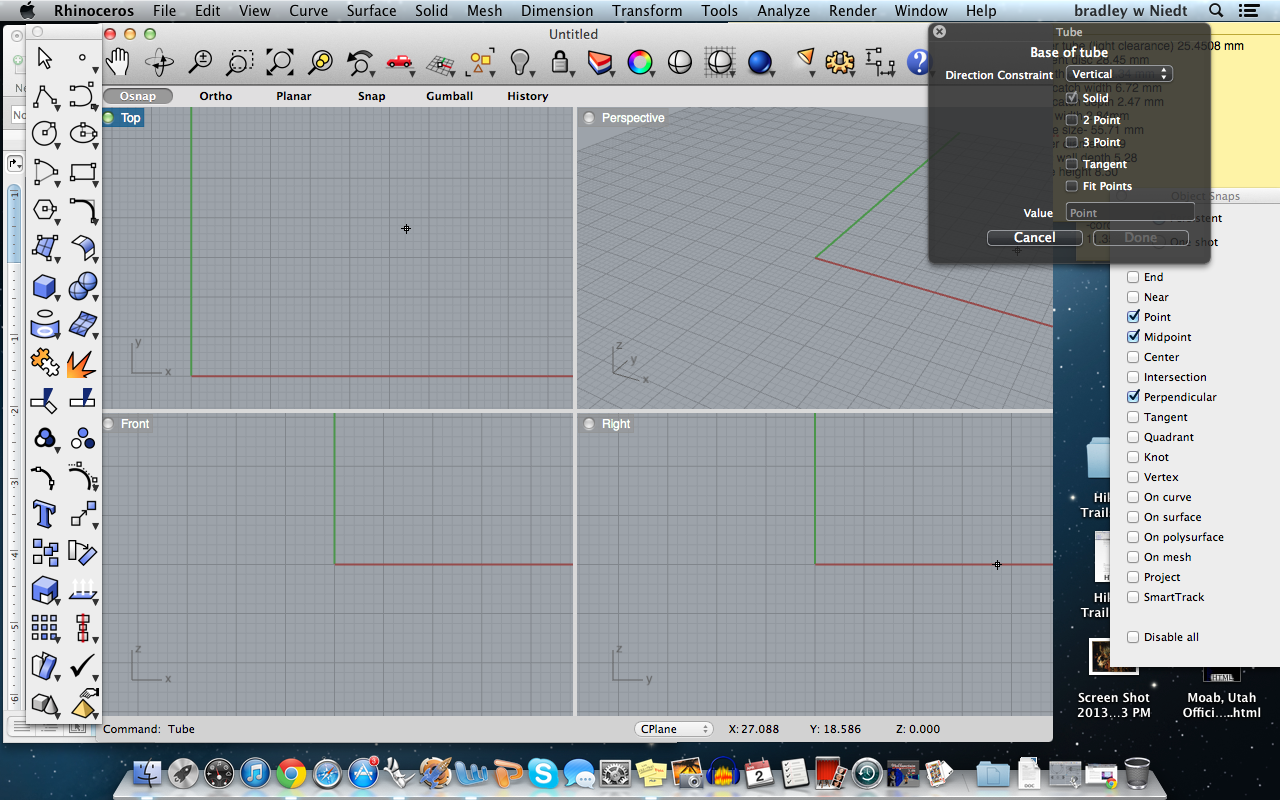
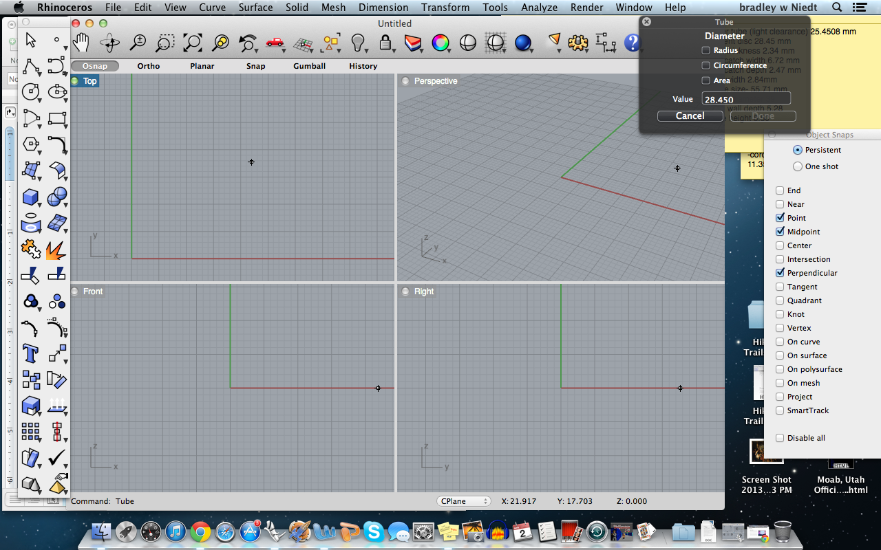
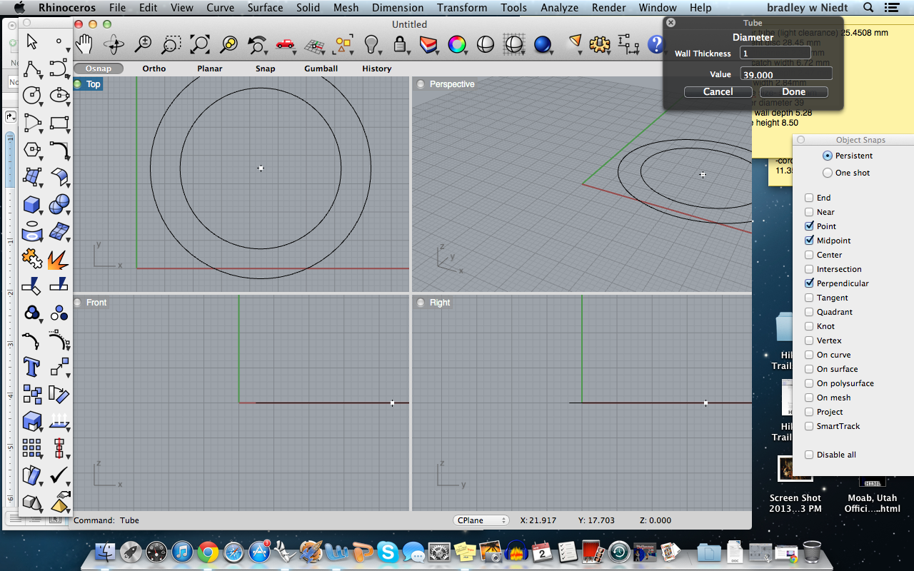
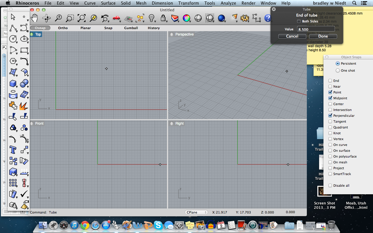
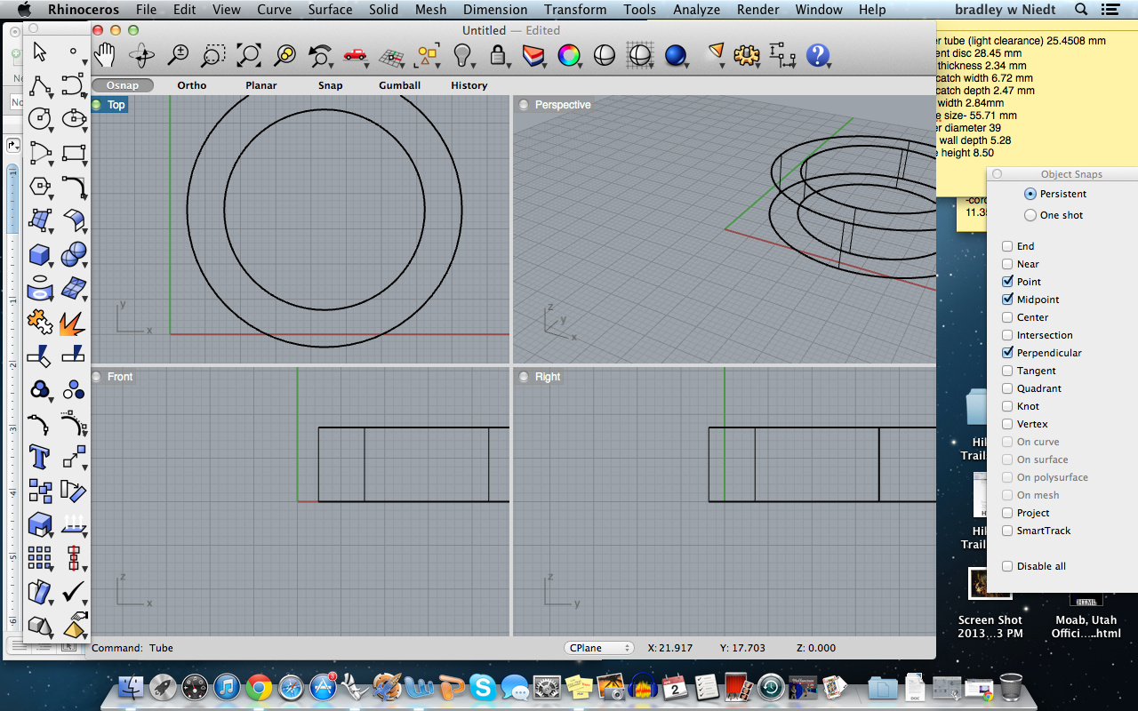
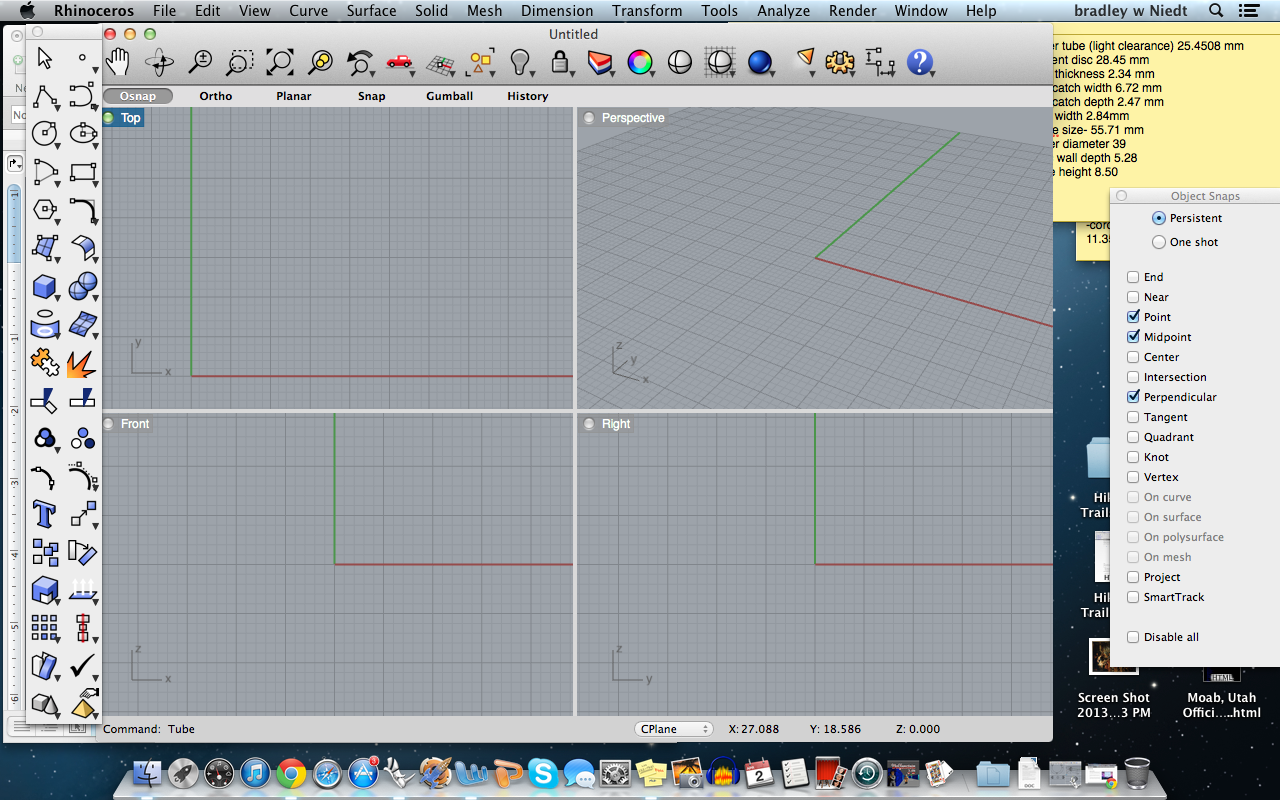
First, we need to create the tube that will be the fitment disc. The steps will get you there, but follow the screenshot pictures I have provided if you are having trouble, the pictures are in chronological order.
In rhino, type “tube” and press enter. The program will ask you to specify the center point, so click in the middle of the Top view, and the center point will be set(image1).
Next, type in the value of the inner diameter of the disc, which is 28.450 mm, and press enter.
Then type in the outer wall diameter of the disc, 39.00 mm, and press enter.
Next, type in the height of the disc, which is 8.50 mm, and press enter.
We now have our tube!
Designing the Screw Holes
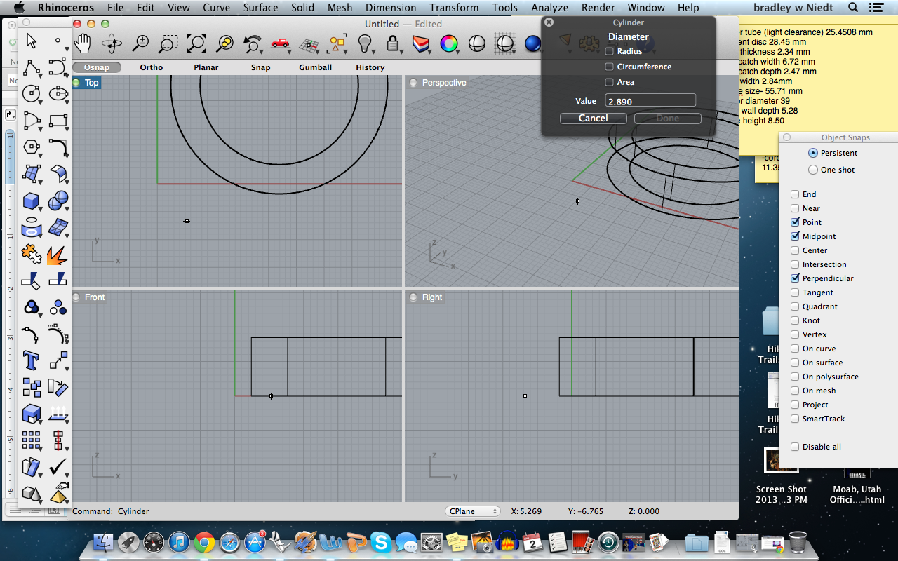
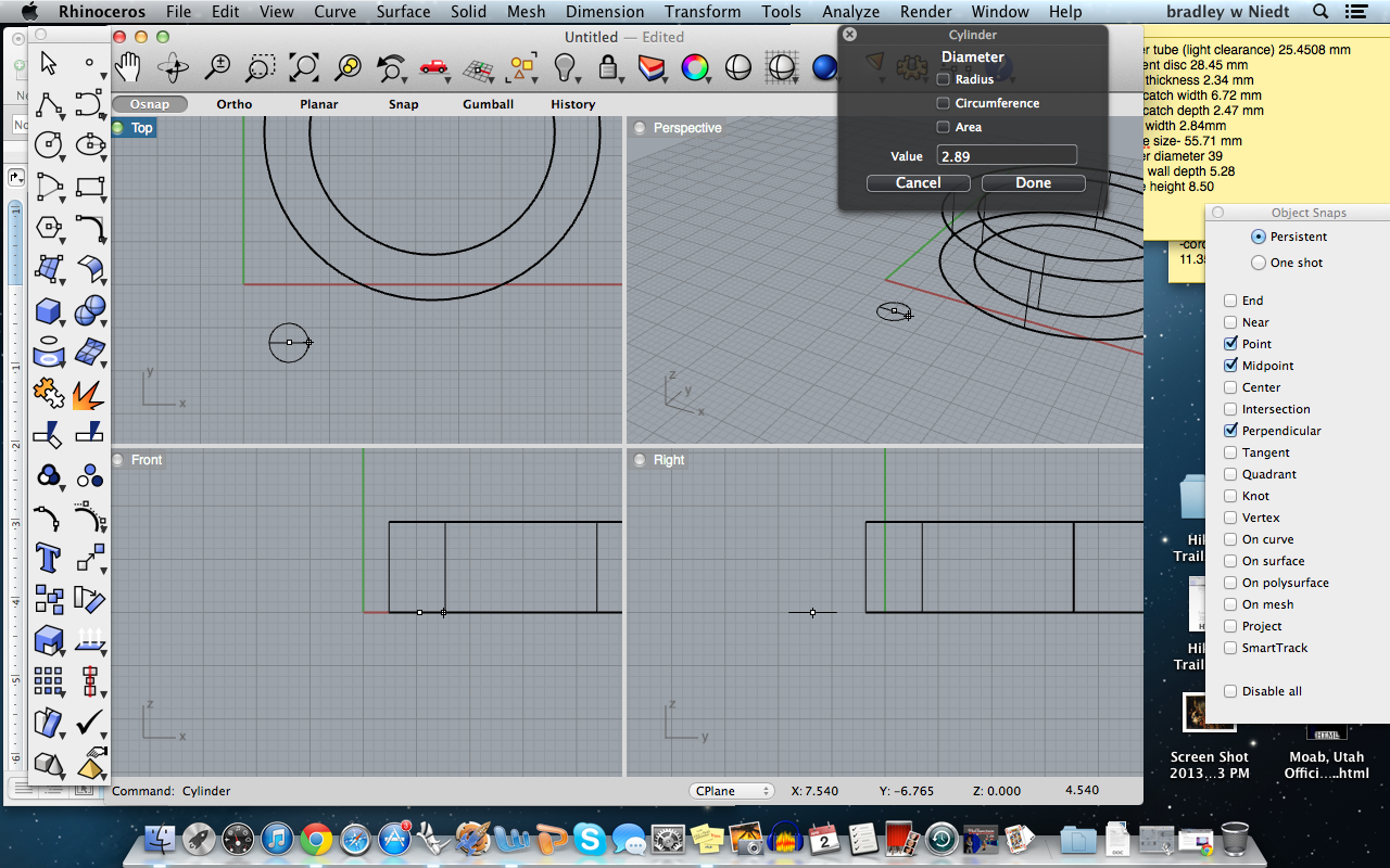
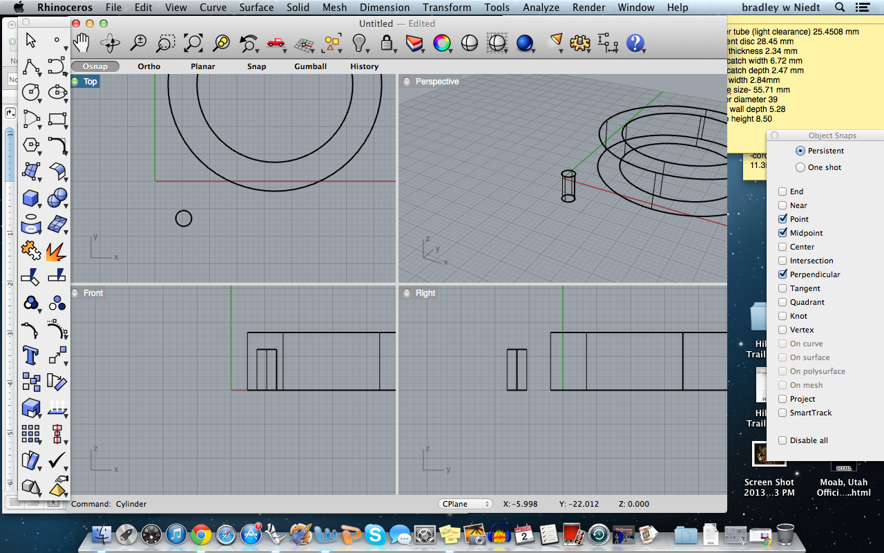
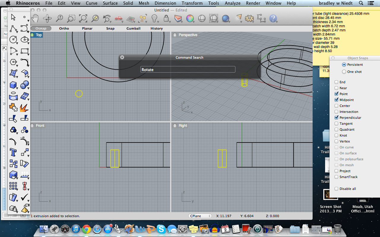
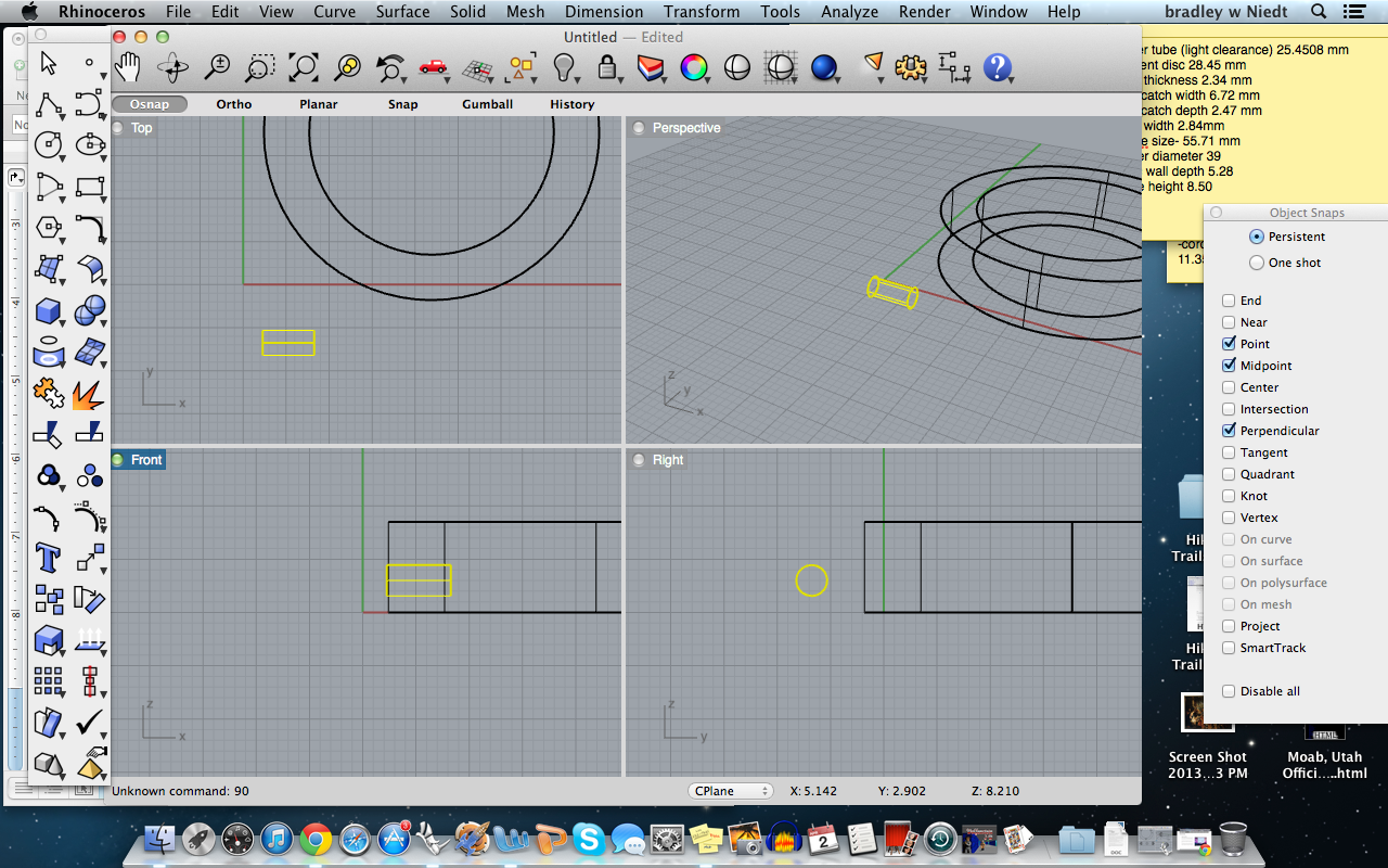
In the command search box, type “Cylinder”, press enter.
Select the point at which you want to create the tube by clicking on the top view.
Then type in the diameter of the tube, 2.89 mm, press enter.
Next, type in the length of the tube, 6 mm, press enter.
Now we have our bolt tube!
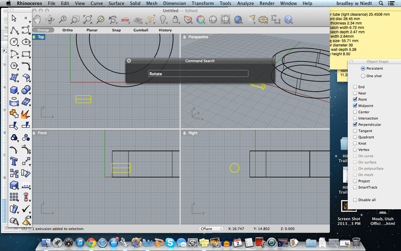
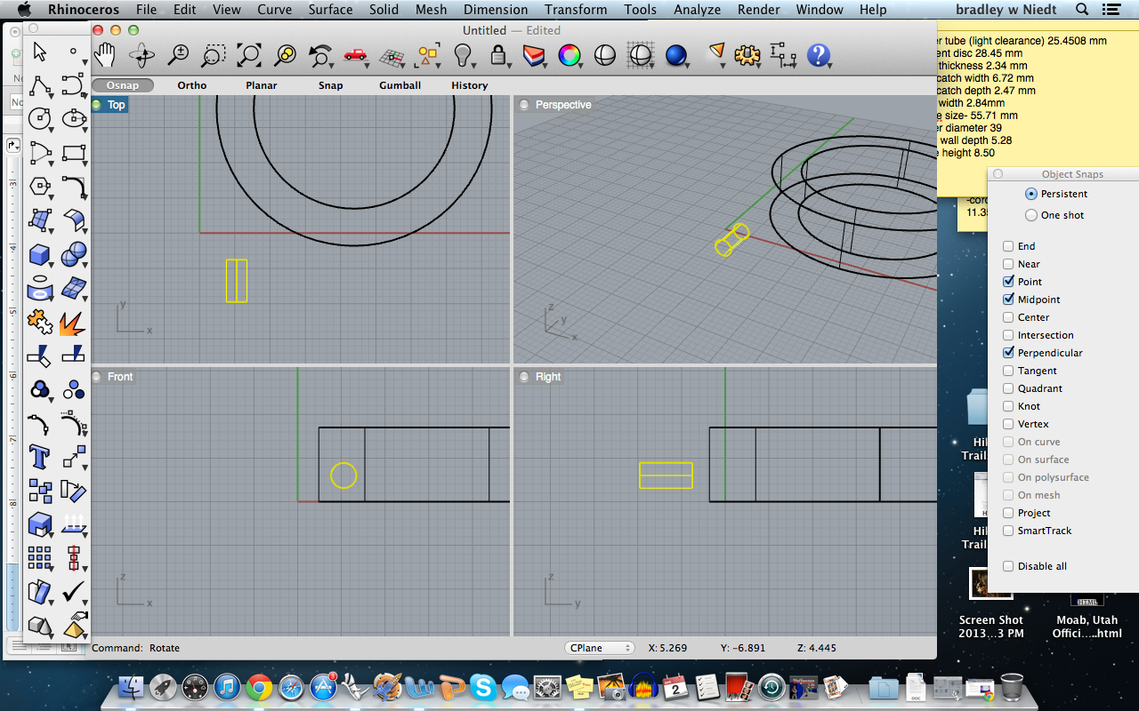
Next, we have to rotate the tube so we can have it horizontally oriented to the disc.
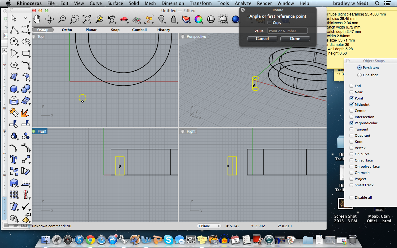
highlight the tube, and type the command: “rotate” and press enter.
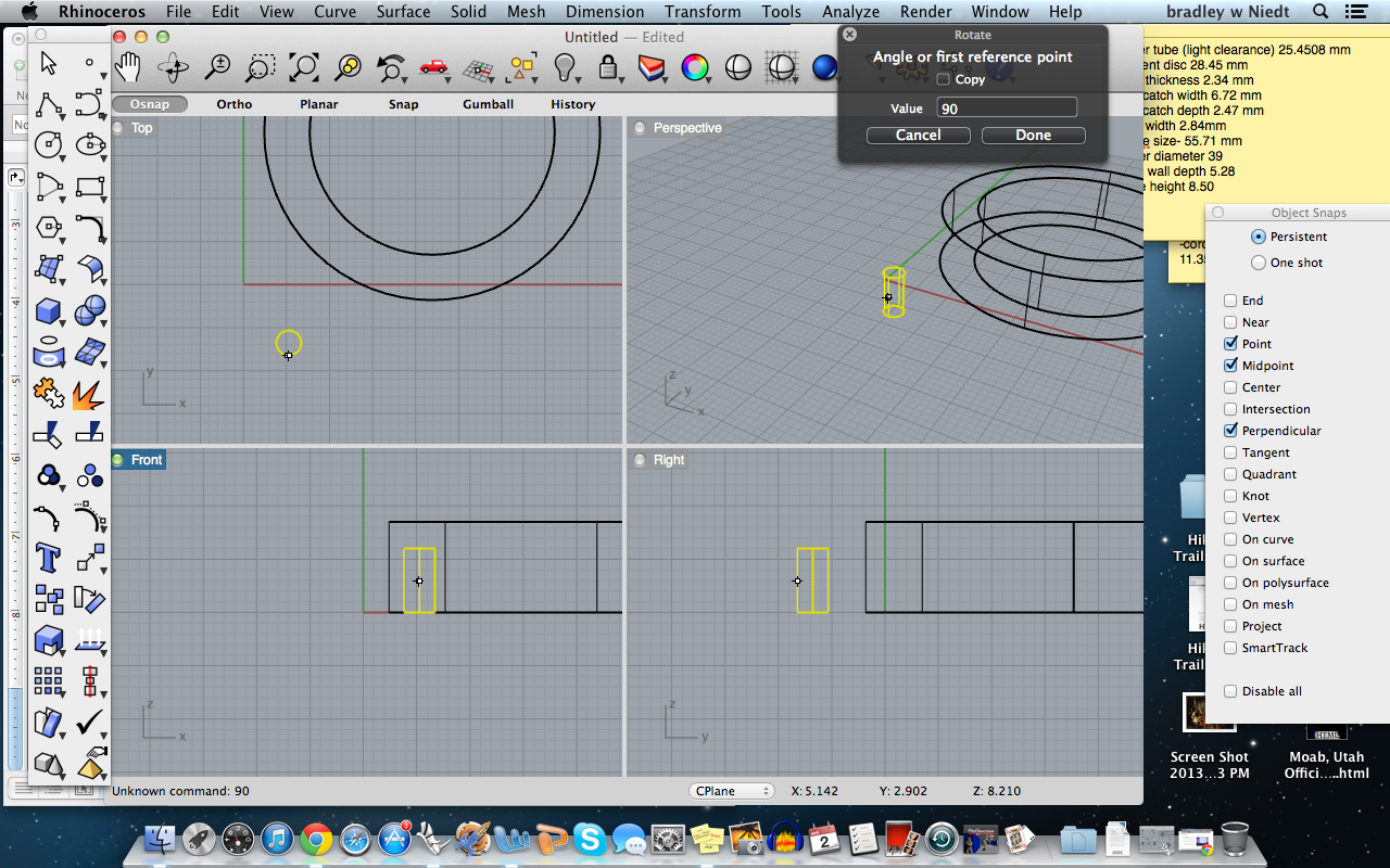
Next, choose the center of the rotation, put your OSnaps on “Midpoint”, and hover your mouse over the midpoint of the tube in the FRONT view, and click on the midpoint to set the center of rotation.
Type in “90” in the rotate command box and press enter.
Next, do the same thing, but choose the center of rotation in the TOP view, so the tube will rotate 90 degrees, making it perpendicular to the quadrant lines on the disc.
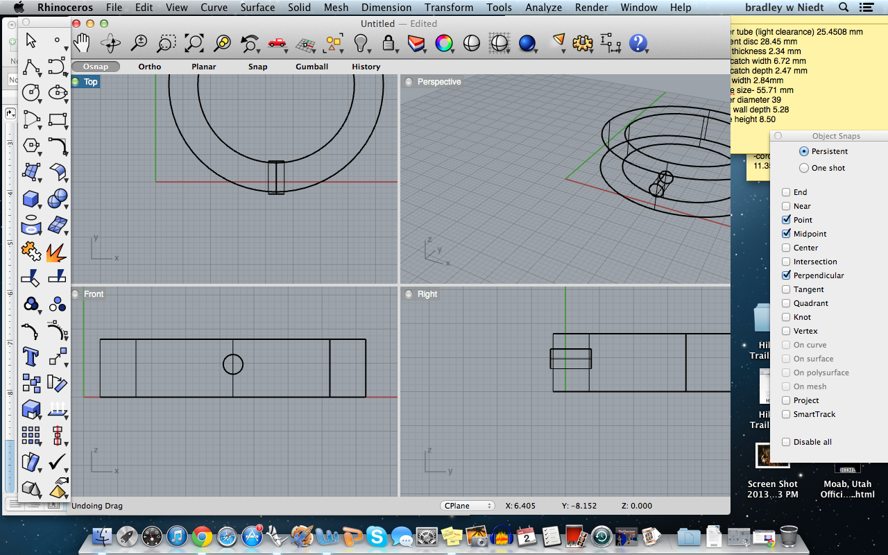
Next, drag the tube to intersect the disc.
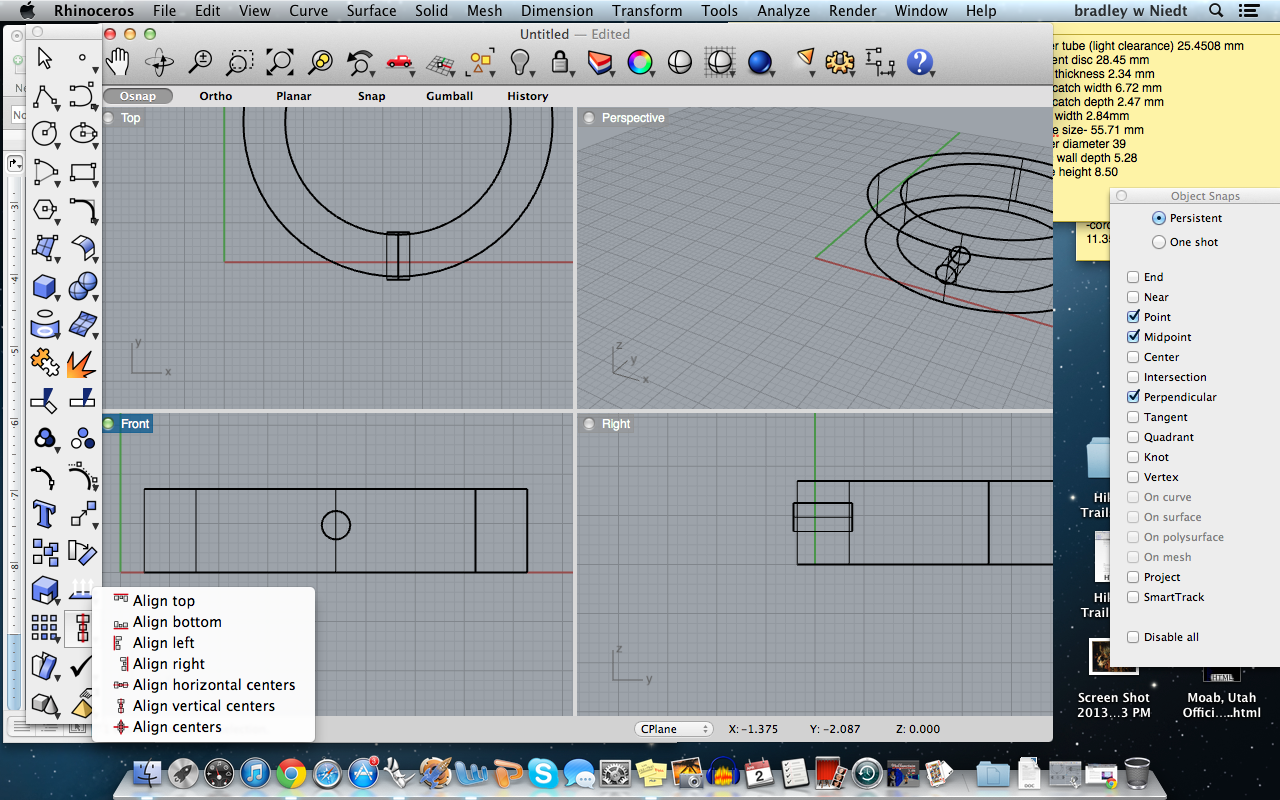
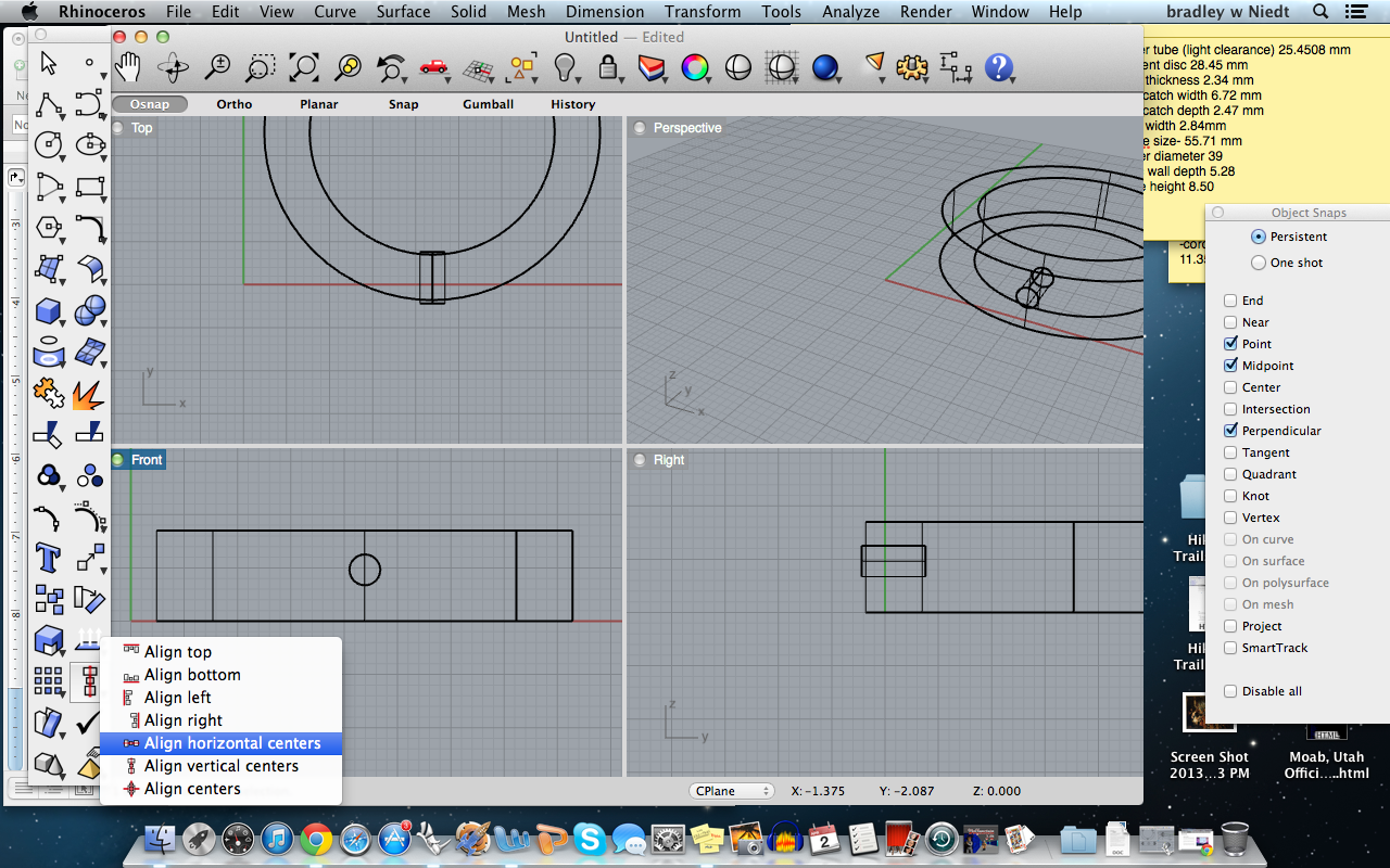
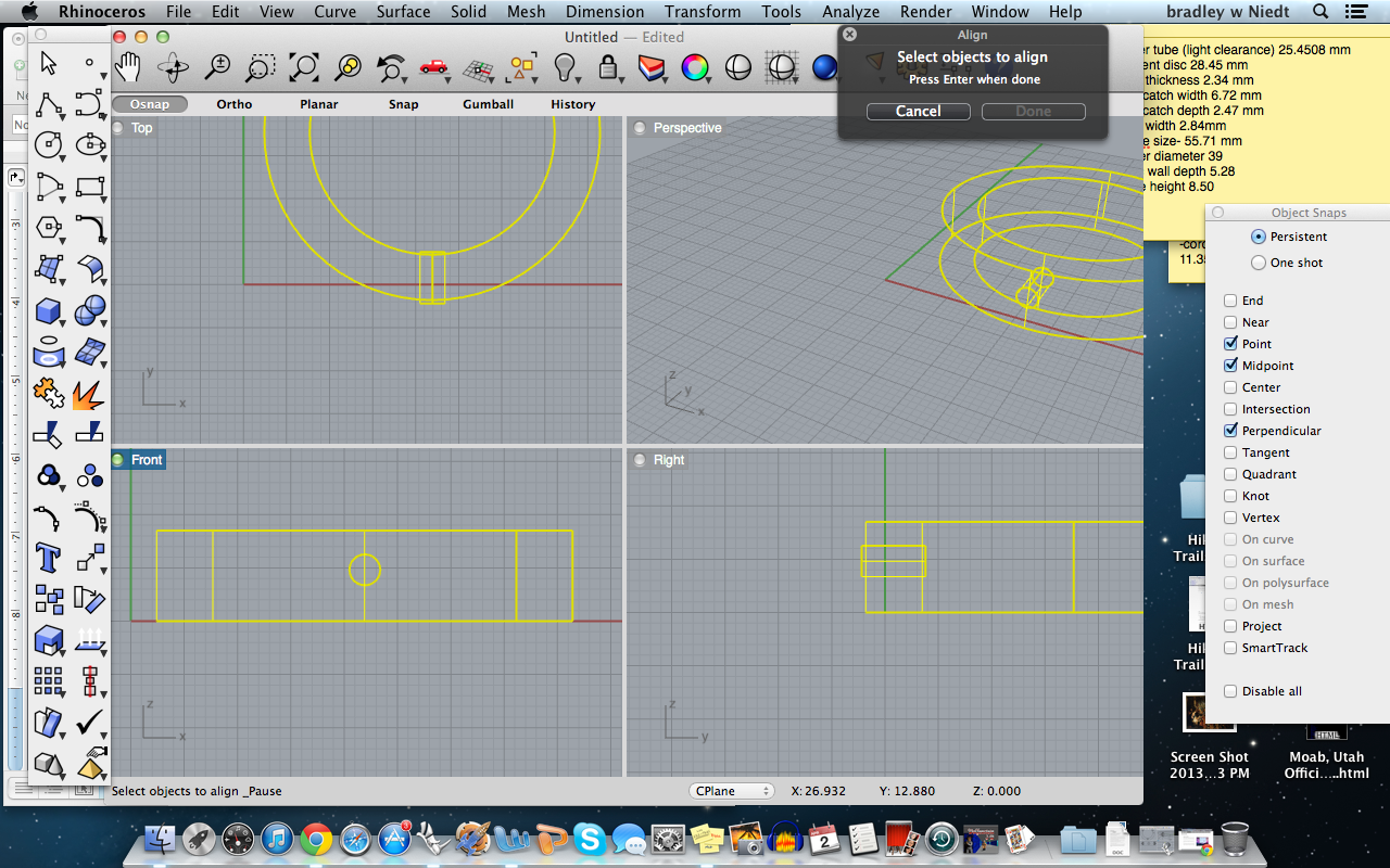
Click on the align box in the toolbox, then select “Align Horiontal Centers”, next, select both the tube and the disc so that they are both highlighted, press enter twice.
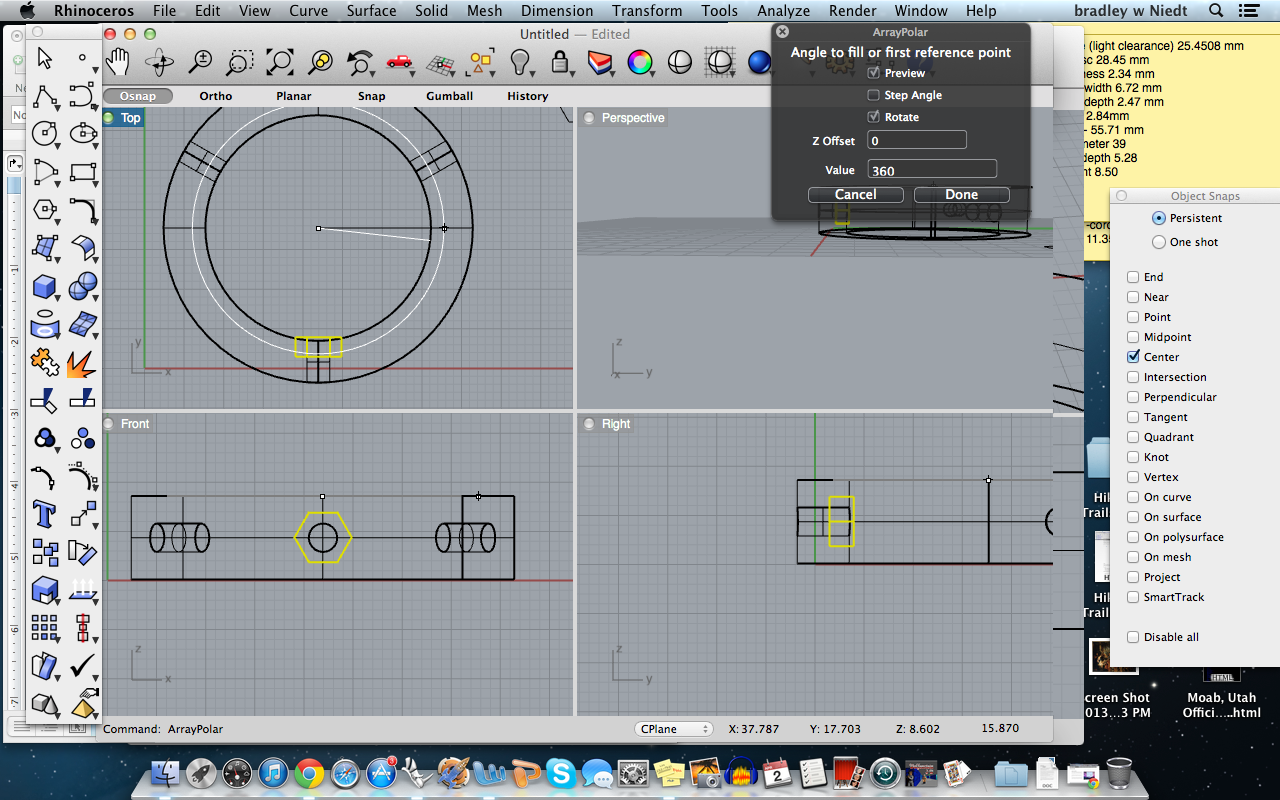
Now that the two are centered, we need to Array the tubes so they array to equal points around the disc.
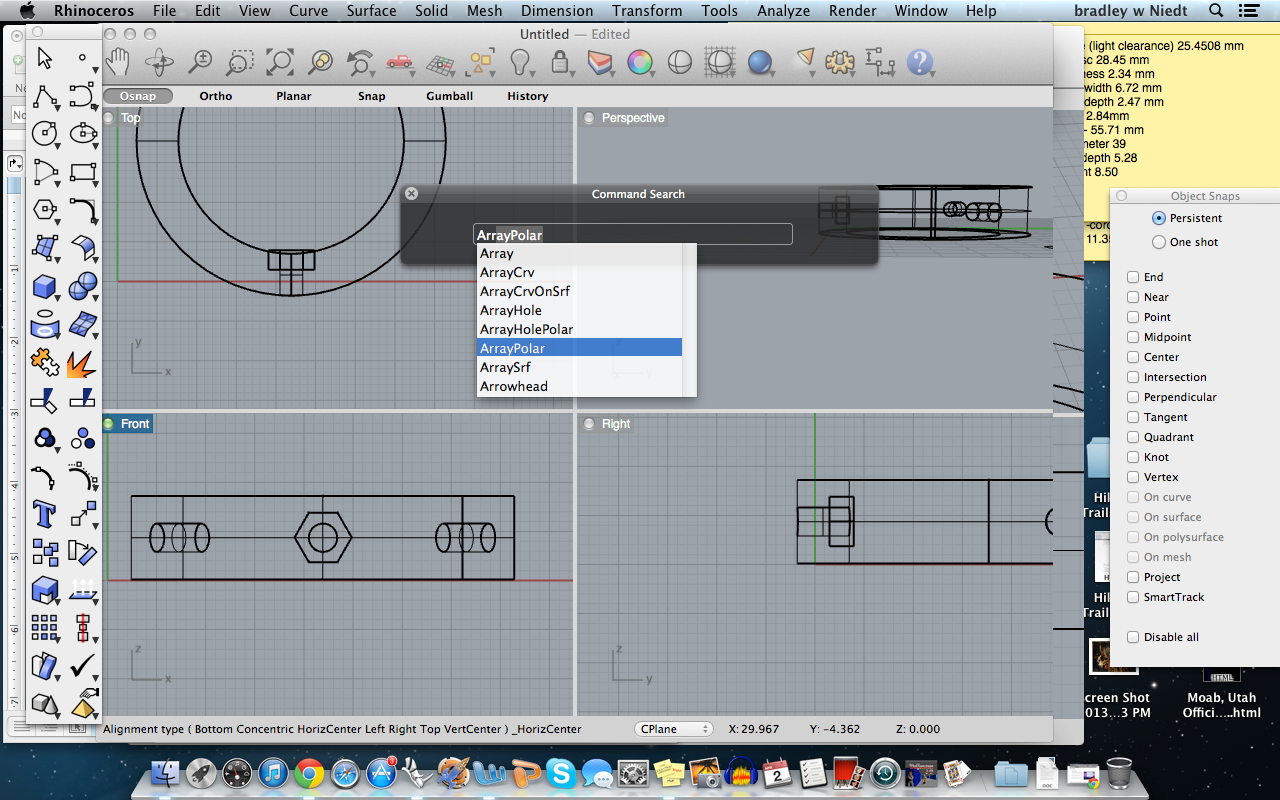
Type in “array” and from the options that drop down, select “ArrayPolar”.
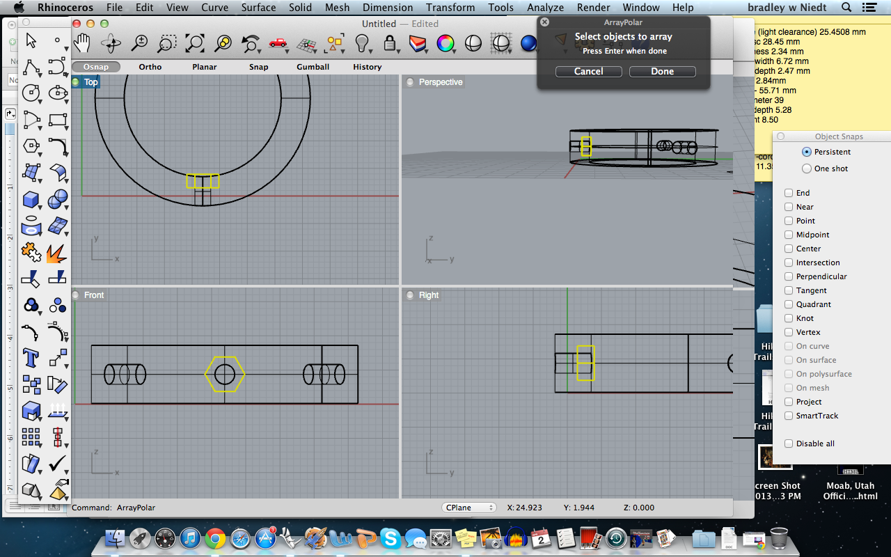
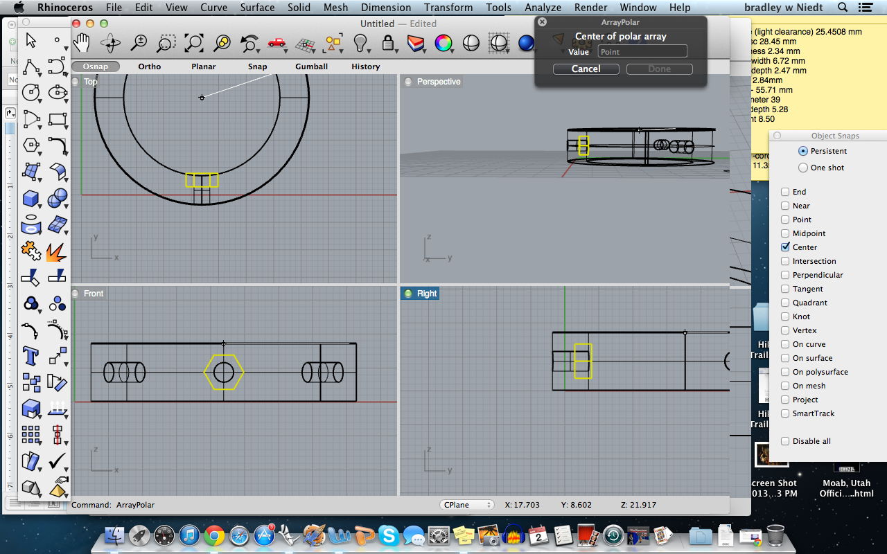
Press enter, and select the tube, press enter. Next you have to select the center of the Array, so check the “center” box on your OSnaps, and hover your mouse around the edge of the disc until it snaps to the center point, when it does, click to select it.
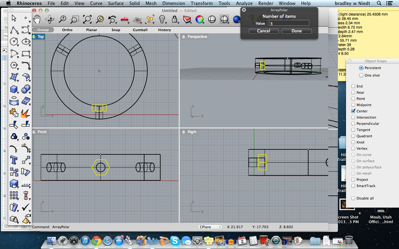
Next, Rhino will have you specify the number of tubes you want to array, type in “3” and press enter.
Next, make sure the array is set to “360” and press enter.
Boolean the Screw Holes
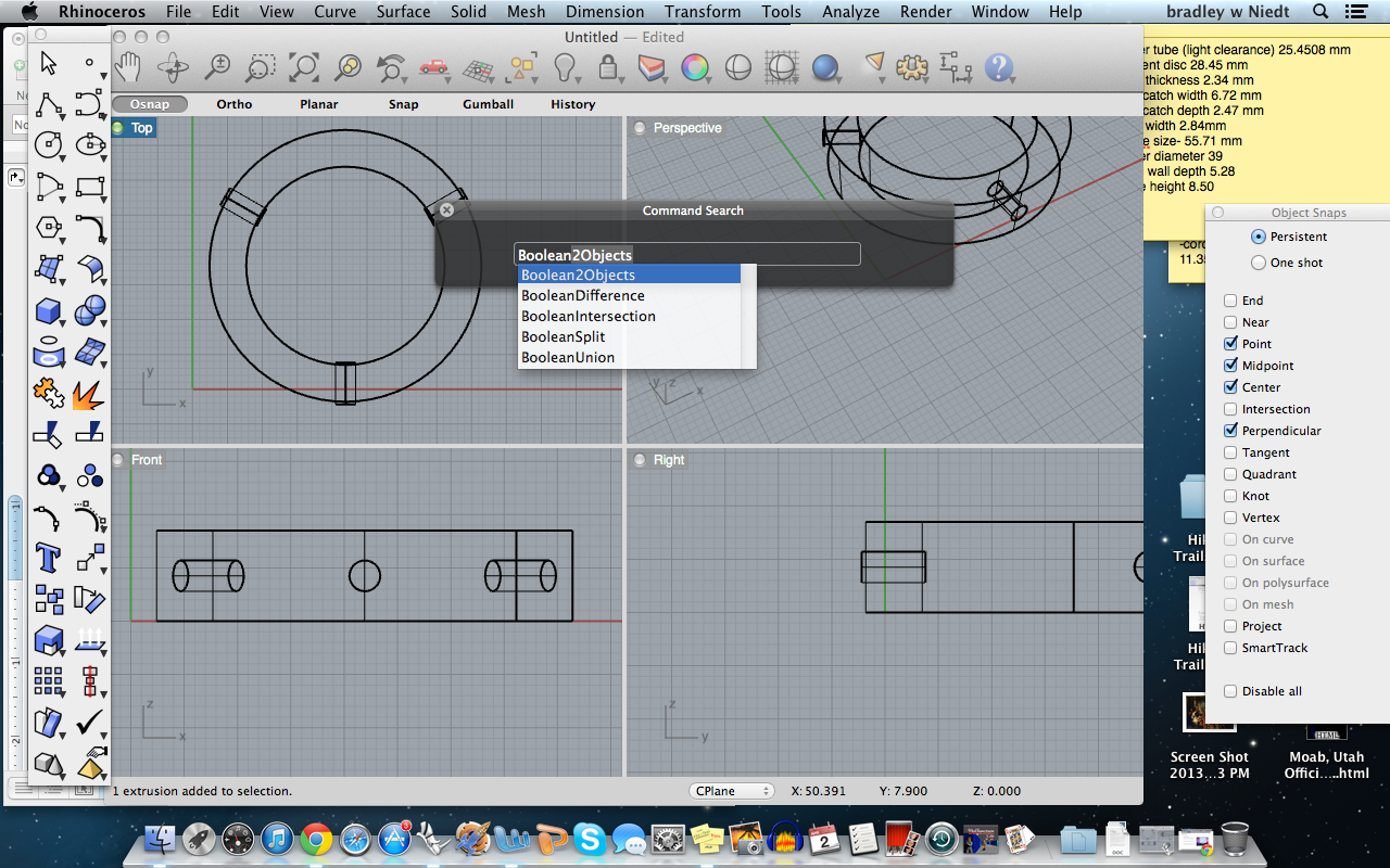
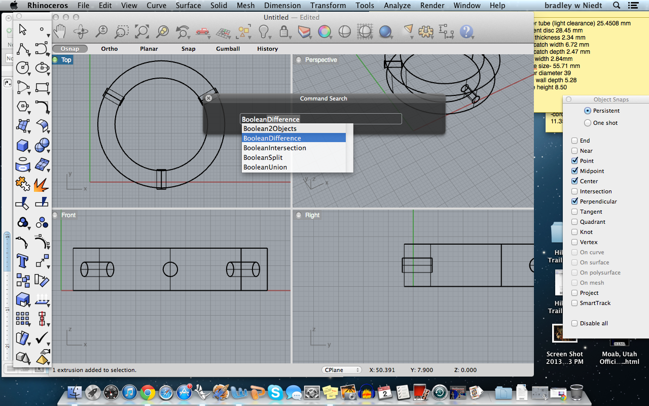
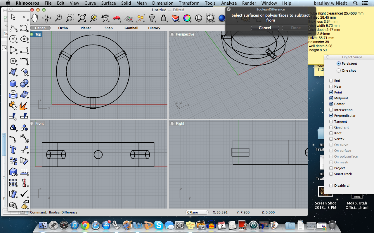
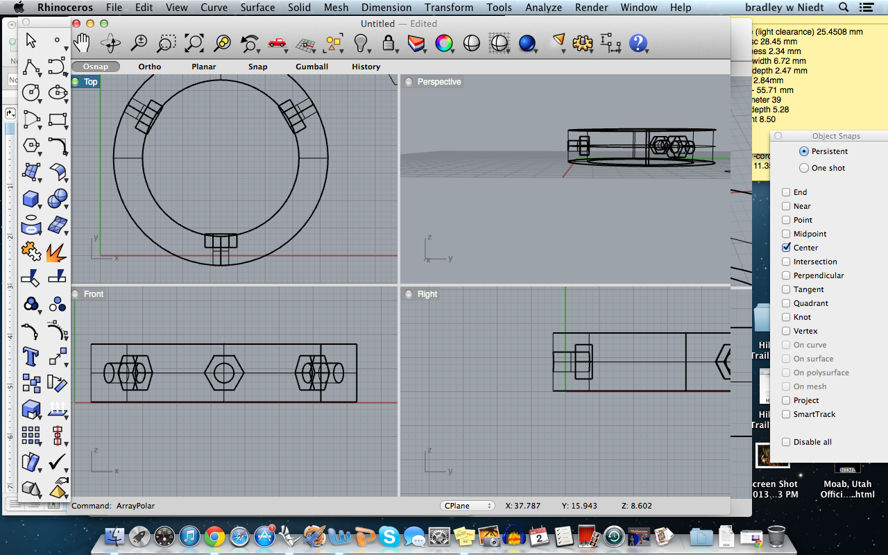
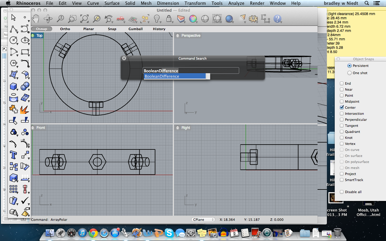
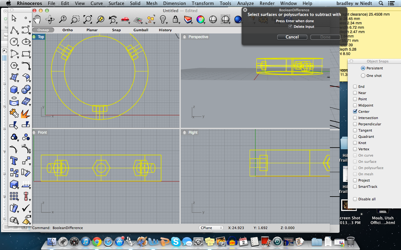
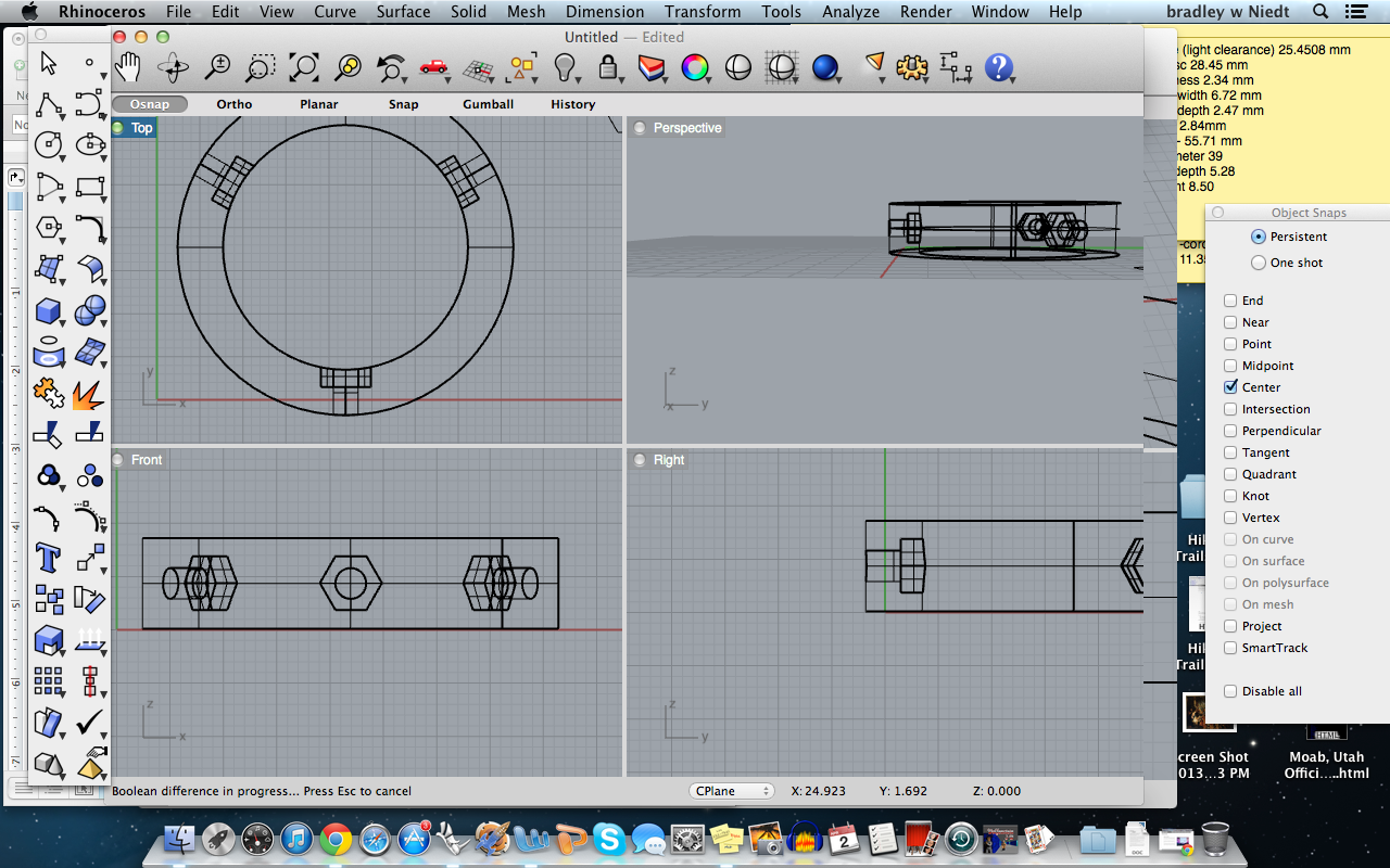
Now that the tubes are Arrayed, we must Boolean difference them from the fitment disc.
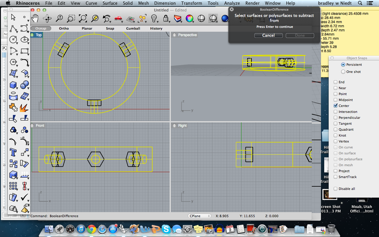
Type “Boolean” into the command search, and select “BooleanDifference”, press enter.
Next, select the fitment disc, from which we will bolean difference the tubes, press enter.
Then select the three tubes and press enter, we’re nearly finished with the disc!
Type “Boolean” into the command search, and select “BooleanDifference”, press enter.
Next, select the fitment disc, from which we will bolean difference the tubes, press enter.
Then select the three tubes and press enter, we’re nearly finished with the disc!
Making the Nut Catches
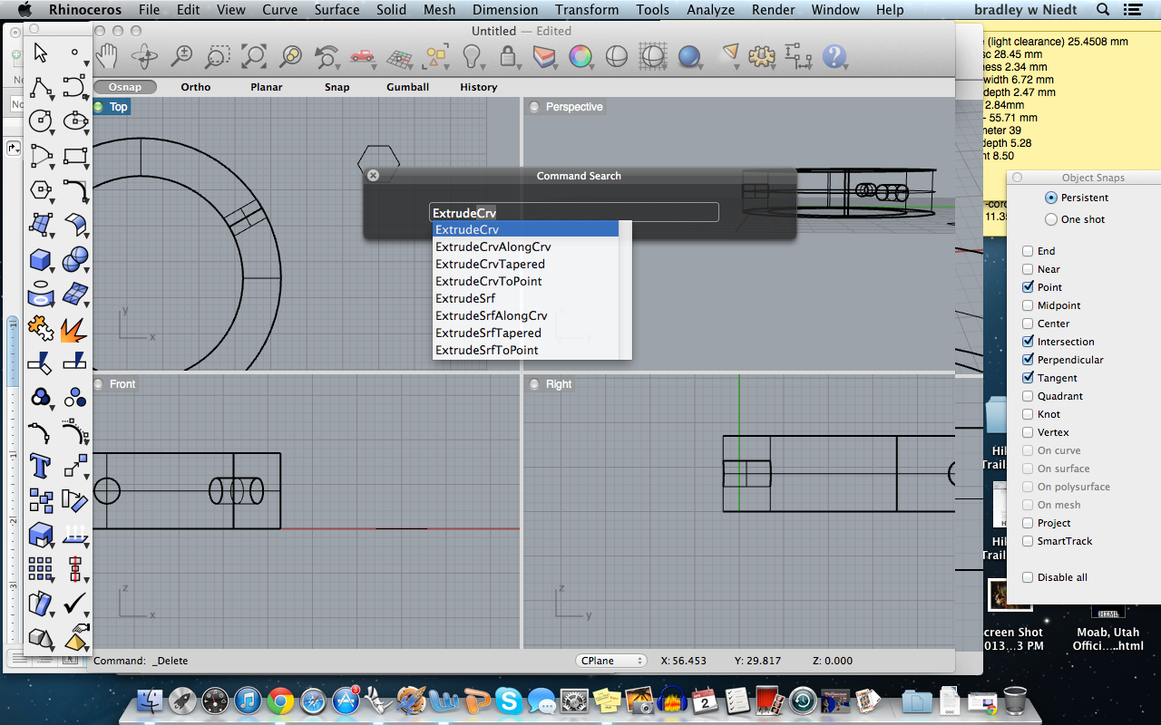
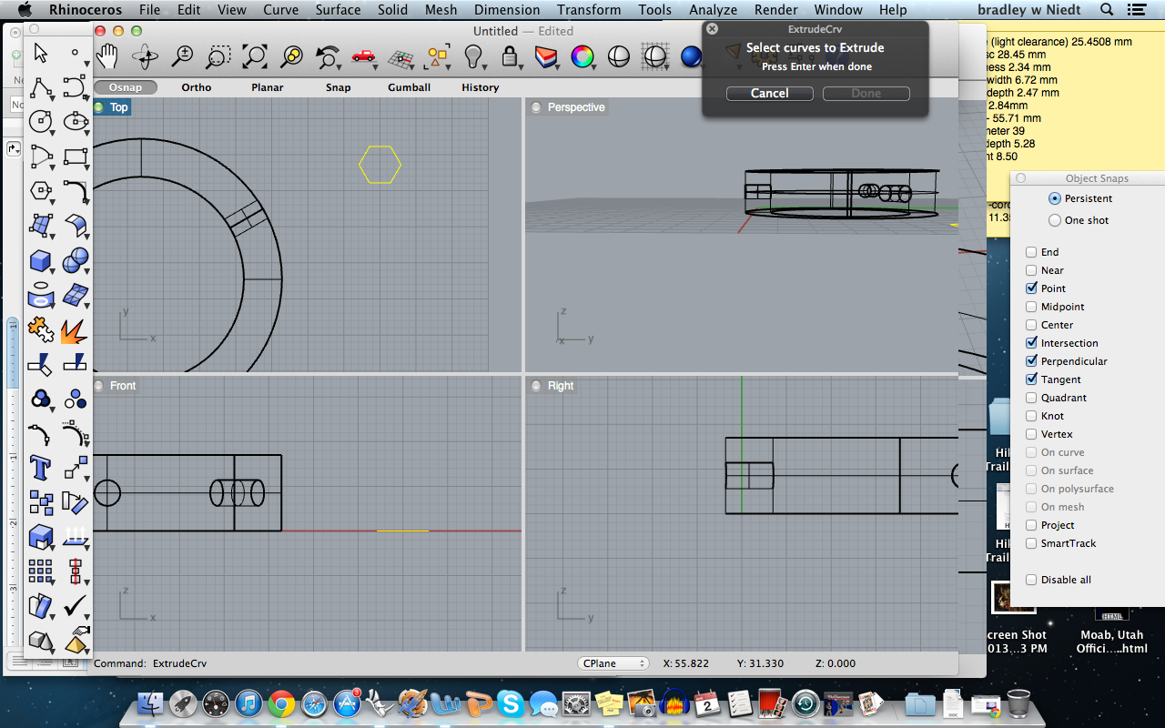
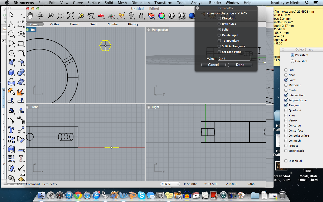
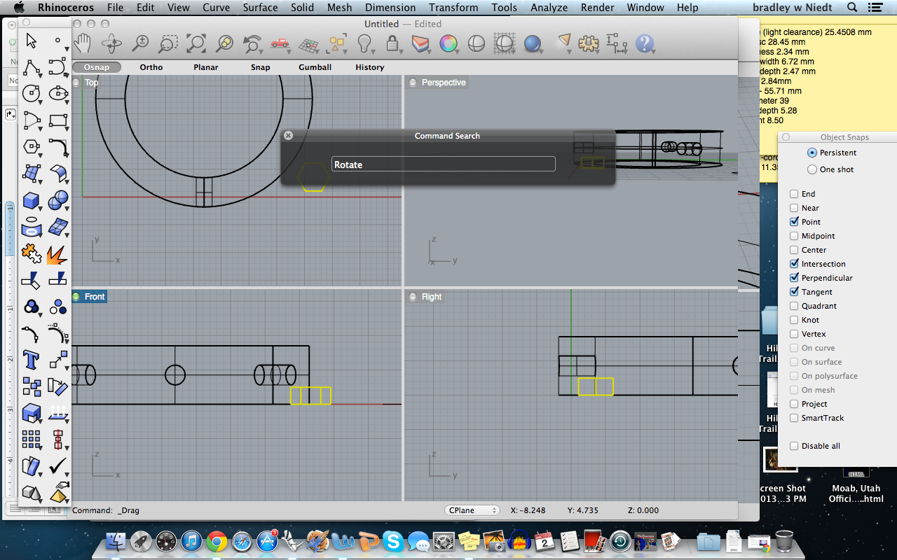
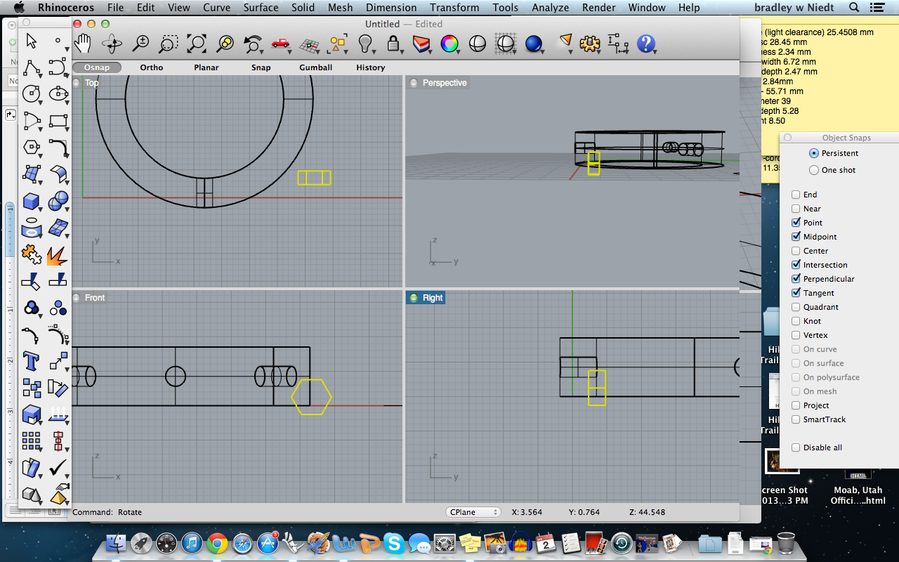
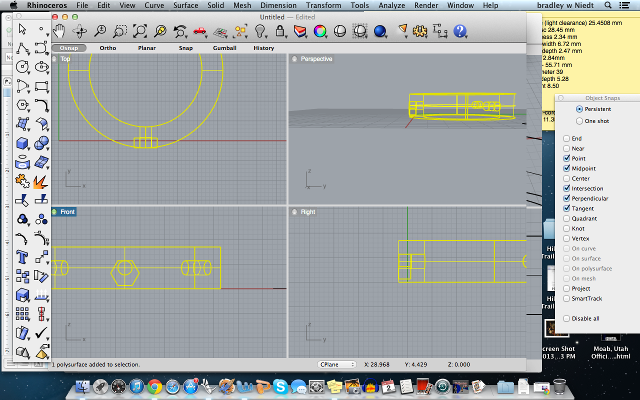
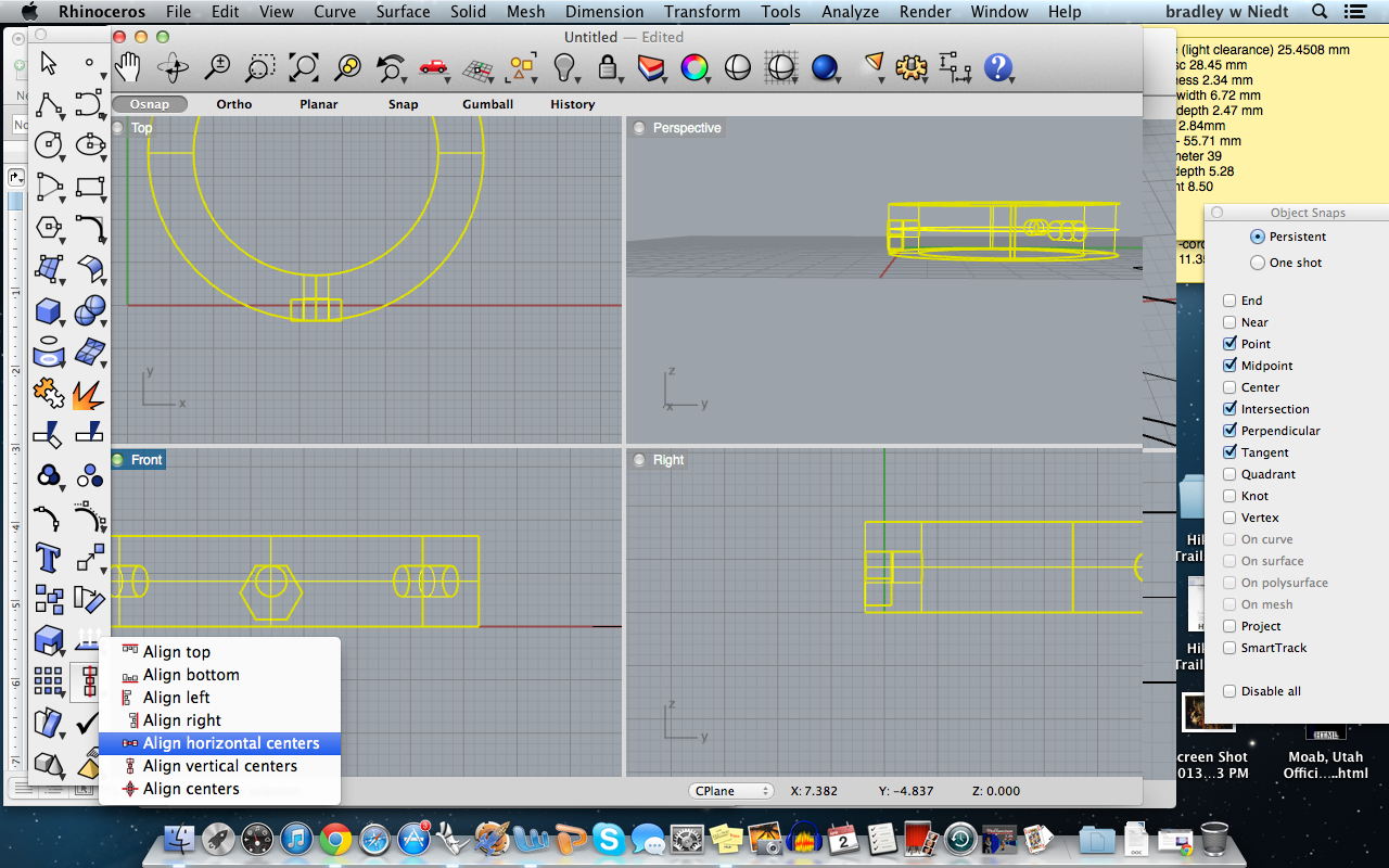
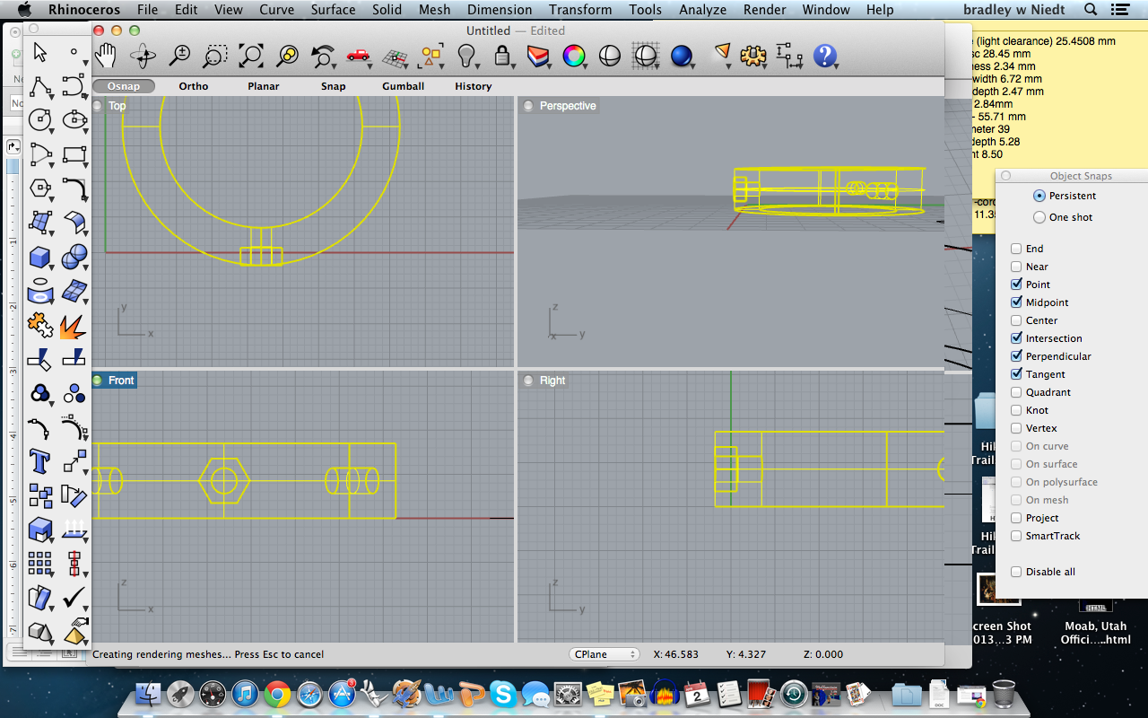
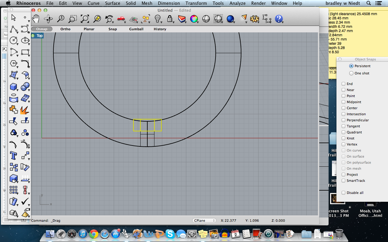
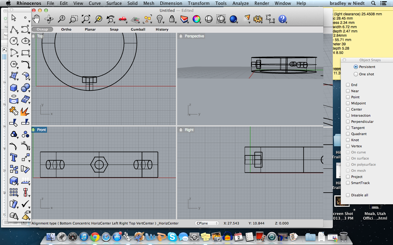
Next, we have to make the nut catch.
Next, select the polygon command from the toolbox., make sure the number of sides is set to 6, check the “edge” box, and select where you want the center point to be, then type in the size of the edge which is 2.91 mm, press enter, then click for the orientation of the hexagon.
Next, type ExtrudeCrv and press enter, then select the hexagon and press enter, now type in the depth of the nut, which is 2.47 mm, and press enter.
We now have our hexagon, and will now position it and array it just like the tube!
First drag the extrusion over next to the disc, and rotate it 90 degrees from its midpoint in the RIGHT view.
Now, drag the extrusion over to the first tube hole in the FRONT view.
In the TOP view, drag the extrusion to the inner circle of the disc, so the extrusion’s tow edge corners touch the inner circle of the fitment disc, allowing the extrusion to protrude slightly from the inner wall of the disc.
Here we will highlight the extrusion and the disc to align them Horizontally in FRONT view.
Now we will polar array the extrusion the same way we did with the tube.
Once the extrusions are arrayed, we will Boolean difference them from the fitment disc.
Finishing Touches and Booleans
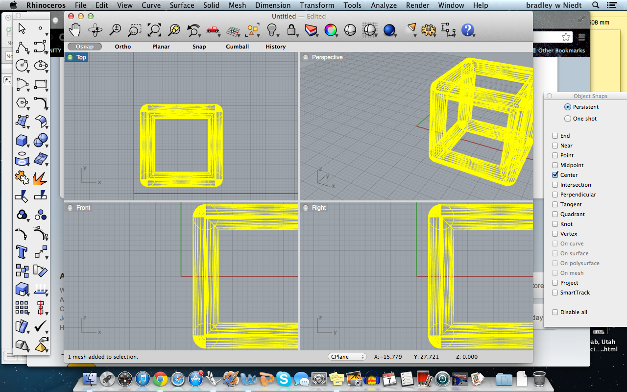
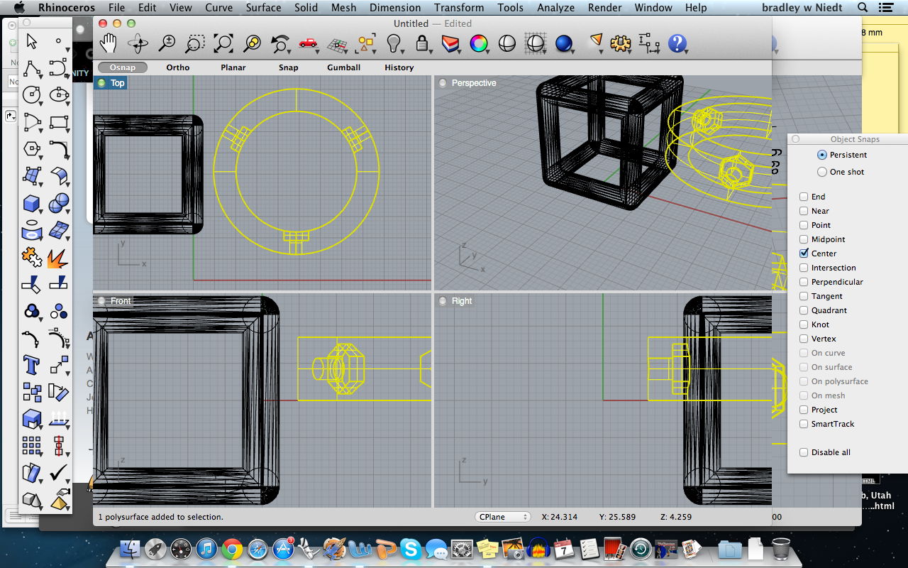
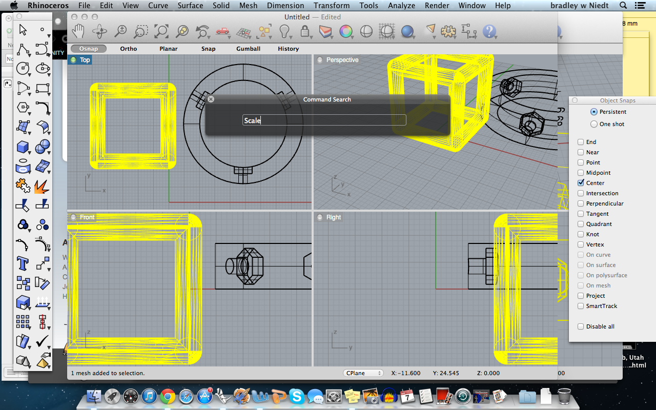
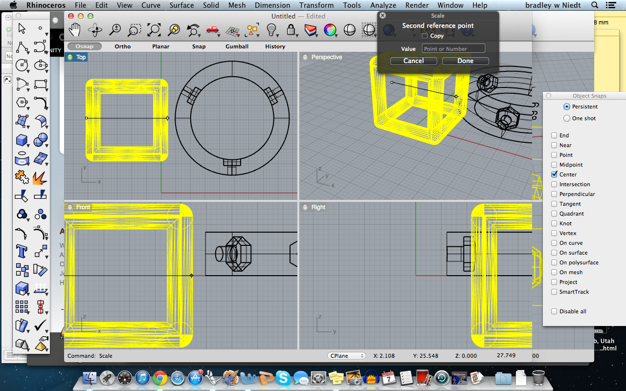
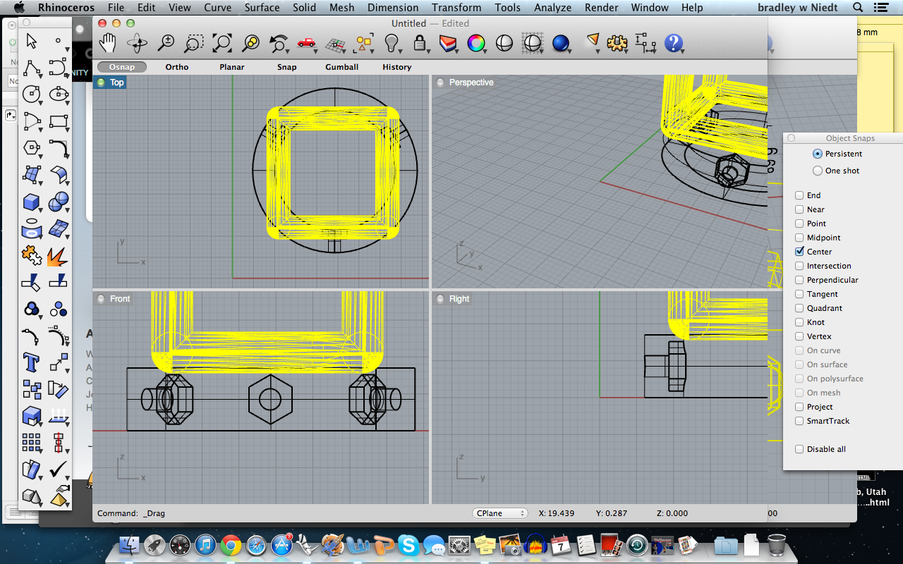
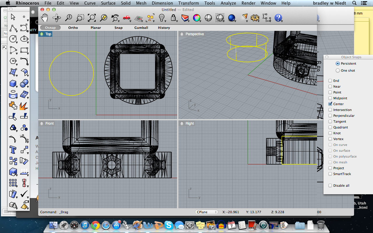
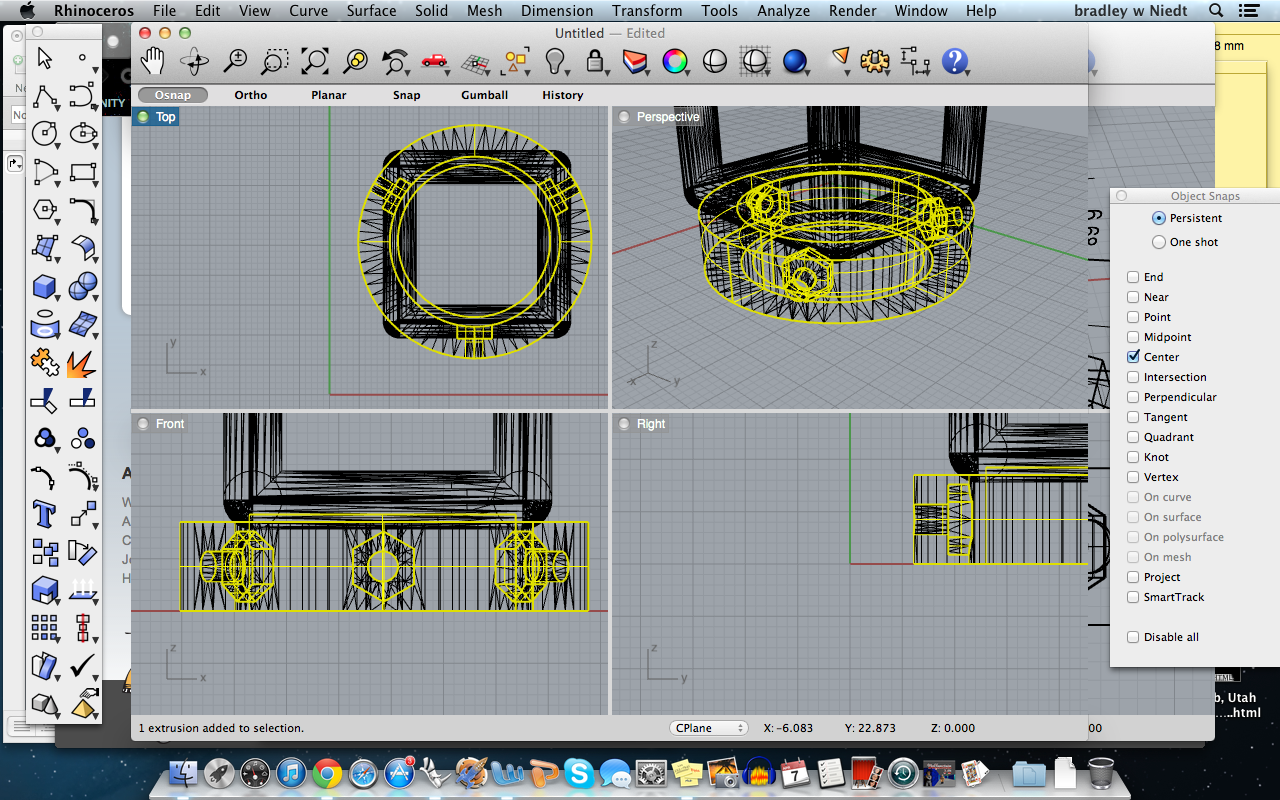
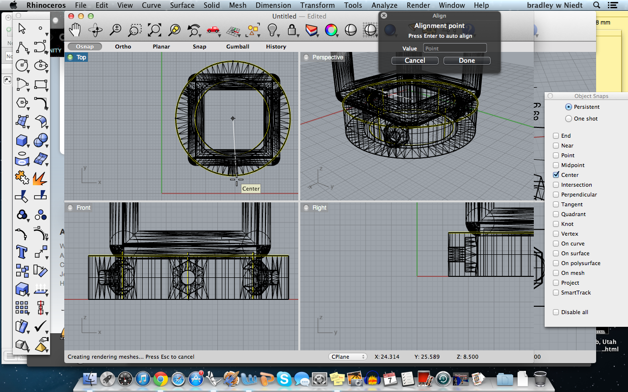
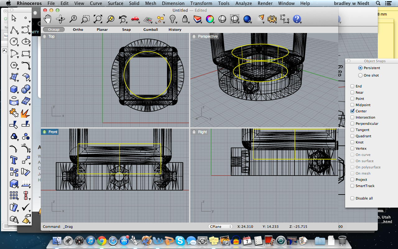
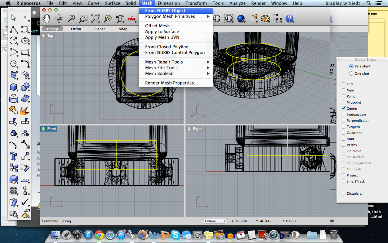
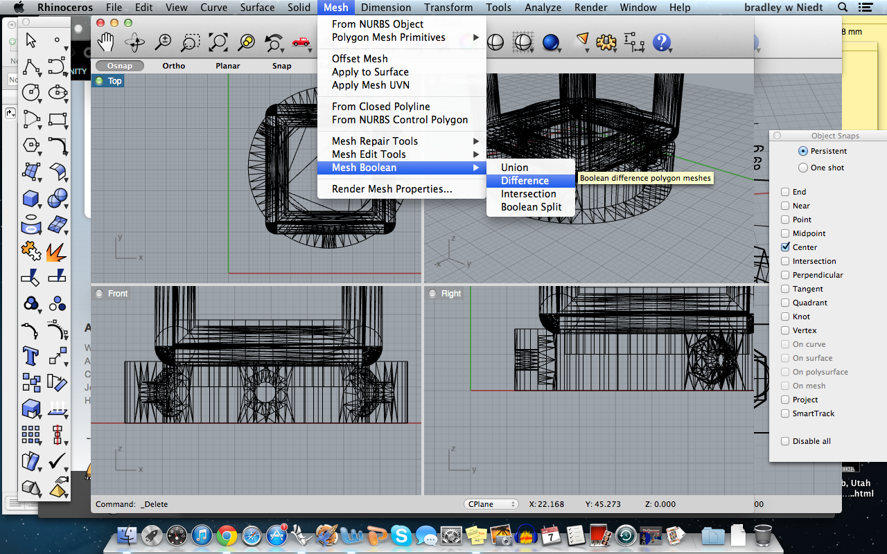
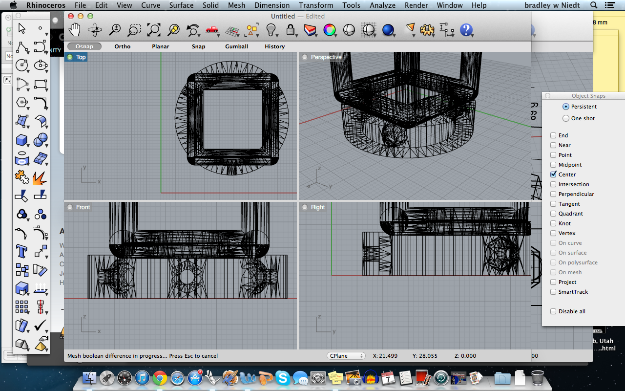
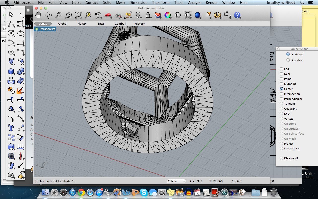
Now, copy and paste the plug we made earlier to be booleaned from the hexahedron.
Next, drag the plug into the center of the fitment disc- here we will align the disc and the plug, then we can raise the plug to Boolean it from the hexahedron.
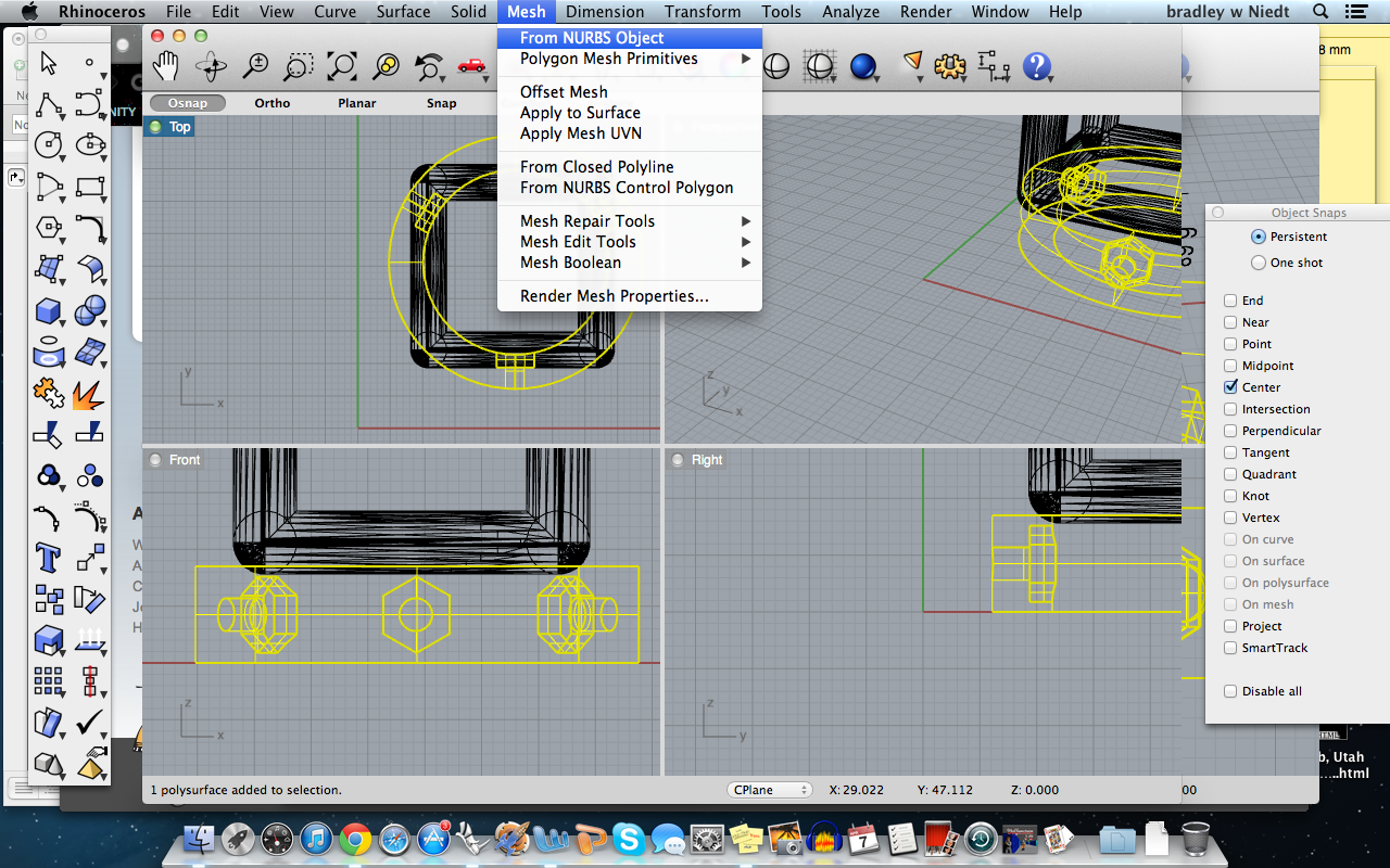
Now that the plug and disc are in place, we will transform the disc and plug into meshes from NURBS. Once the meshes are created, you can delete the polysurfaces, as they are no longer needed.
First we will Boolean difference the plug from the hexahedron by selecting mesh>mesh Boolean>difference. Then you select the hexahedrn first, press enter, then click on the plug and press enter. The plug will now be Boolean differenced away from the hexahedron.
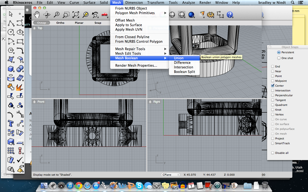
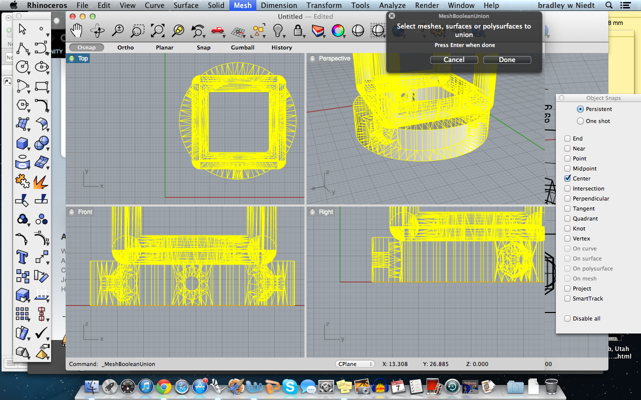
Now we will Boolean Union the disc and the Hexahedron only, to do this, you select mesh>mesh Boolean>Union. Then you select the disc mesh and the hexahedron mesh, and press enter.
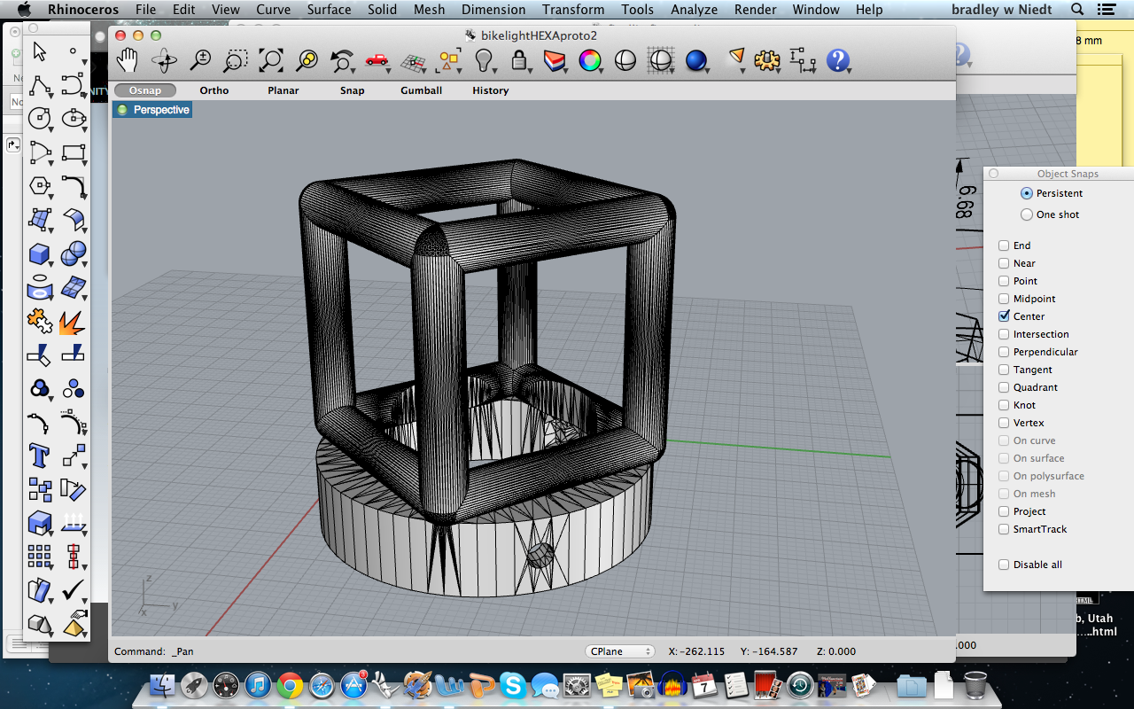
You now have joined the two meshes to complete the design! Hurrah!
Send It Off to Be Printed-Or Print It Yourself!

.jpeg)
.jpeg)
.jpeg)
.jpeg)
.jpeg)
Now, you should save the file to your computer, then export it as a .stl file so you can open it with 3D printing software, or send it to somewhere like shapeways.com where they’ll print it for you!
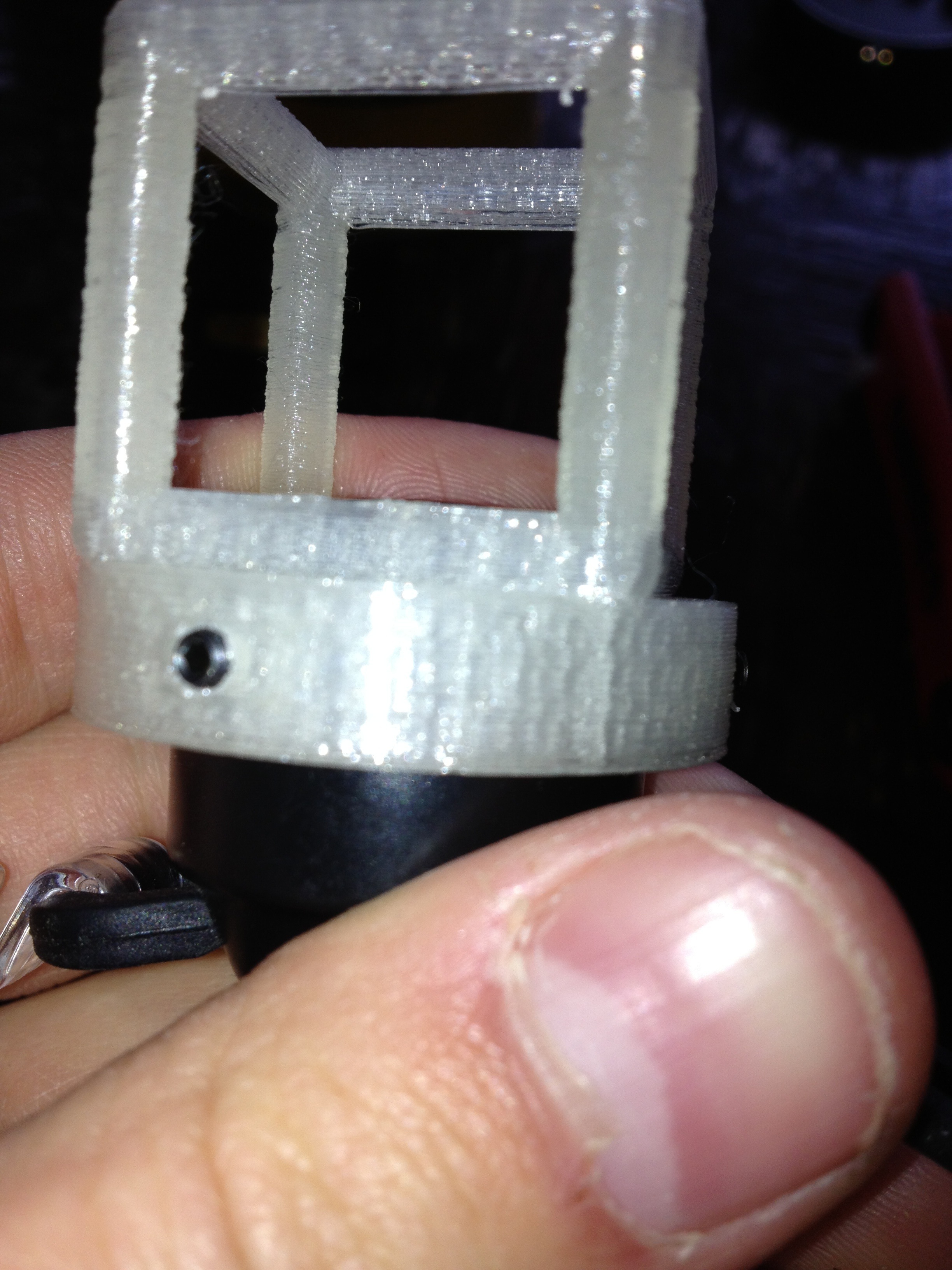
Once you've received the finished print, you need to sand the inner edges of the fixture so they slip easily over the light, this is not because the design is wrong, but because the printed plastic tends to ooze a bit outward as it cools.
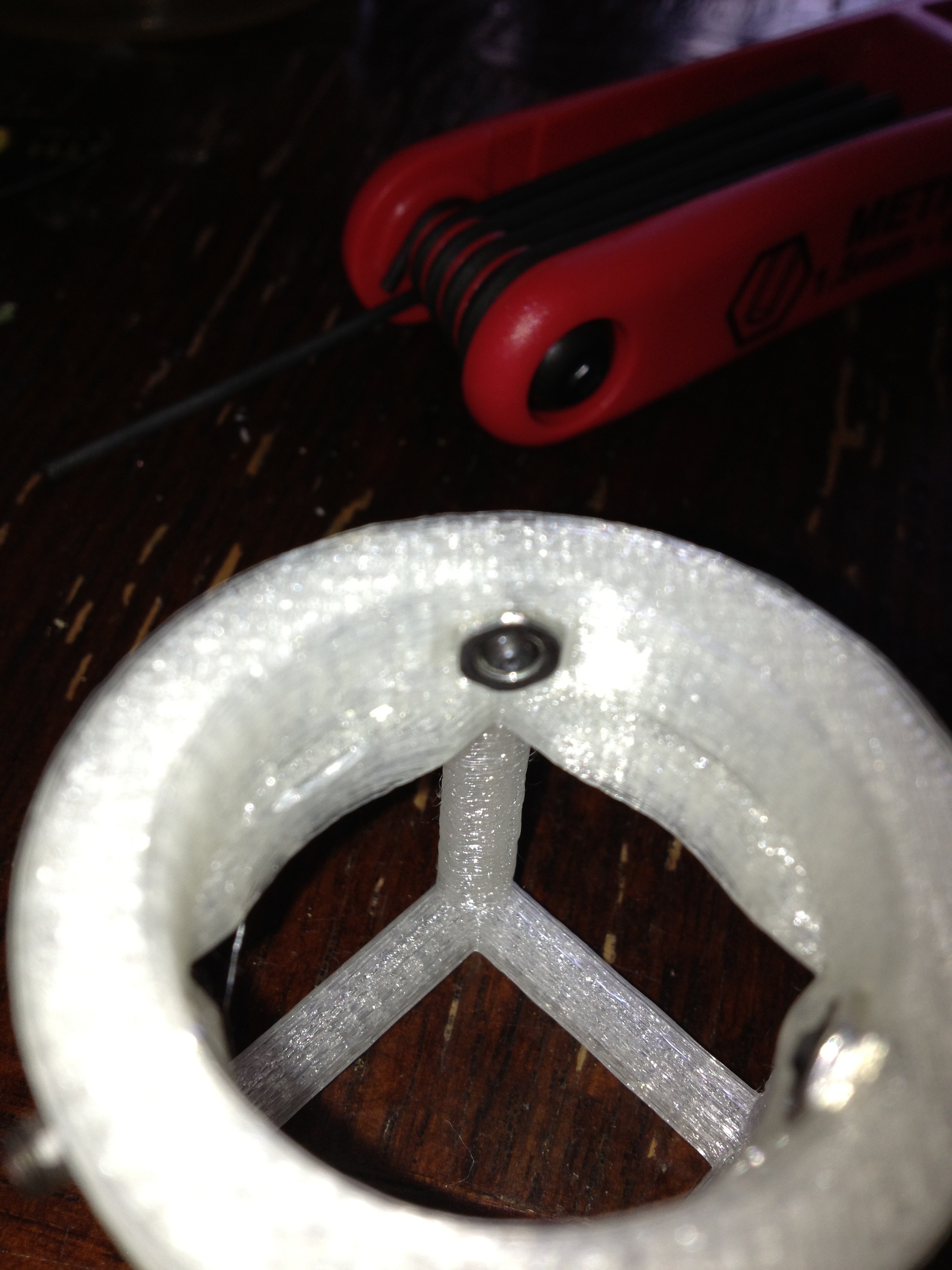
Install the screws and nuts in their spots, and slip the fixture over the light.
With an Allen wrench, tighten the screws until they are firmly grabbing the light, but not too hard because you could damage the plastic cover of the light.
Once you've finished these steps, it's time to put it on your bike and ride! Wahoo!