How to Change Rate of Blinking of LED Using Potentiometer in Arduino Uno.
by videohelp4u in Circuits > Arduino
5593 Views, 4 Favorites, 0 Comments
How to Change Rate of Blinking of LED Using Potentiometer in Arduino Uno.

This video contains sets of commands and codes writing that enable a potentiometer to change the rate of blinking of LED in arduino uno board using '123d circuits' online open platform for circuit making , program compiling and simulation of circuit.
Basic Introduction to the Video Tutorial and the Goal of This Tutorial.

This tutorial deals with writing an arduino program for controlling the rate of blinking of an LED by installing a potentiometer in arduino microcontroller.Also this video displays the connection of the componenets to be used to integrate the circuit on arduino uno board and also on how to simulate the circuit.
Go to Create the Circuit on Online Platform and Write the Corresponding Arduino Program.

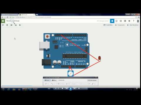
In this video we're using an online simulation platform namely "123d circuits",where one will require to follow the steps as shown in the video to form the physical integration of the circuit with the given peripheries.
Physical Connection to Create the Circuit.

Standard potentiometer consists three terminals - one for supply input voltage as shown in this video, terminal 1 to be connected to +5 volt,one to be grounded as for terminal 3 is concerned and wiper terminal to be connected to anode terminal of the LED and finally cathode terminal of LED to be grounded to make the connection complete to be run.
Writing Codes for the Circuit on 'code Editor'of the Given Platform to Simulate the Circuit.

The program writing steps involve :
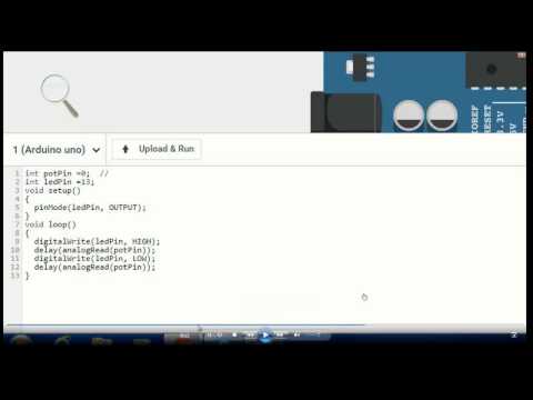
1) assigning input viz potentiometer pot pin as input and LED pin as output as the corresponding port number on micro controller board.
2) declaring led pin as output with the conventional syntax used in arduino program such as "pinMode(ledPin, OUTPUT);"
3)Implementing loop function to set high output state on led pin to illuminate the LED and turn LED off by cutting off the output signal to the led pin by setting over a delay function in between the 'ON' and 'OFF' state.This delay interval is determined by potentiometer's characteristic of reading analog values from 0-1024 digital pulse, so that it can control the rate of blinking of LED/LEDs.
4) finally simulate the circuit by clicking 'Upload and Run' button.