How to Add More Outputs to Your Microcontroller
by TECH GEEK in Circuits > Microcontrollers
17531 Views, 35 Favorites, 0 Comments
How to Add More Outputs to Your Microcontroller
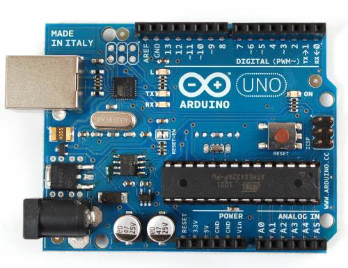
This Instructable will show you step-by-step how to add 8 extra digital outputs, using only 3 of your microcontroller's digital outputs.
Which Microcontroller Should You Use?

In order to do this Instructable with your microcontroller, you will need to make sure that it has the following:
(3x)......Available Digital Outputs (Analog/PWM Outputs will work too)
(1x)......Ground/GND Pin
(1x)......10k (or more) of programming space
(3x)......Available Digital Outputs (Analog/PWM Outputs will work too)
(1x)......Ground/GND Pin
(1x)......10k (or more) of programming space
Parts
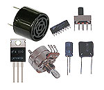


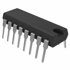
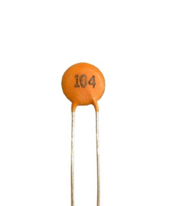
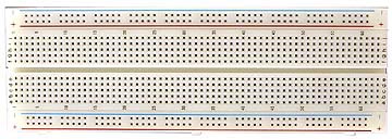
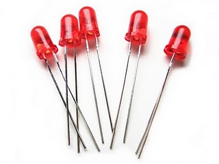
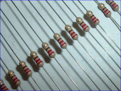
The parts needed to do this Instructable include:
(1x)......Microcontroller
(1x)......1 to 2 foot Length of Breadboard compatible wire
(1x)......74HC595 IC
(1x)......0.1uF ceramic cap (Code = 104)
(1x)......Breadboard
(8x)......20mA LEDs (of any color)
(8x)......220 Ohm resistors
(1x)......Microcontroller
(1x)......1 to 2 foot Length of Breadboard compatible wire
(1x)......74HC595 IC
(1x)......0.1uF ceramic cap (Code = 104)
(1x)......Breadboard
(8x)......20mA LEDs (of any color)
(8x)......220 Ohm resistors
Tools

(1x)......Wire stripper
(1x)......Wire cutter
(1x)......Power supply
(1x)......USB Cable (or relevant programming method)
(1x)......Computer with your microcontroller's programming software installed
Wire It Up (Part 1)
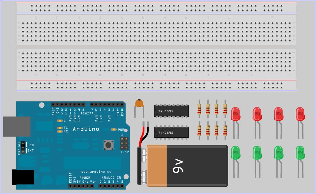
Start by gathering your parts.
Wire It Up (Part 2)
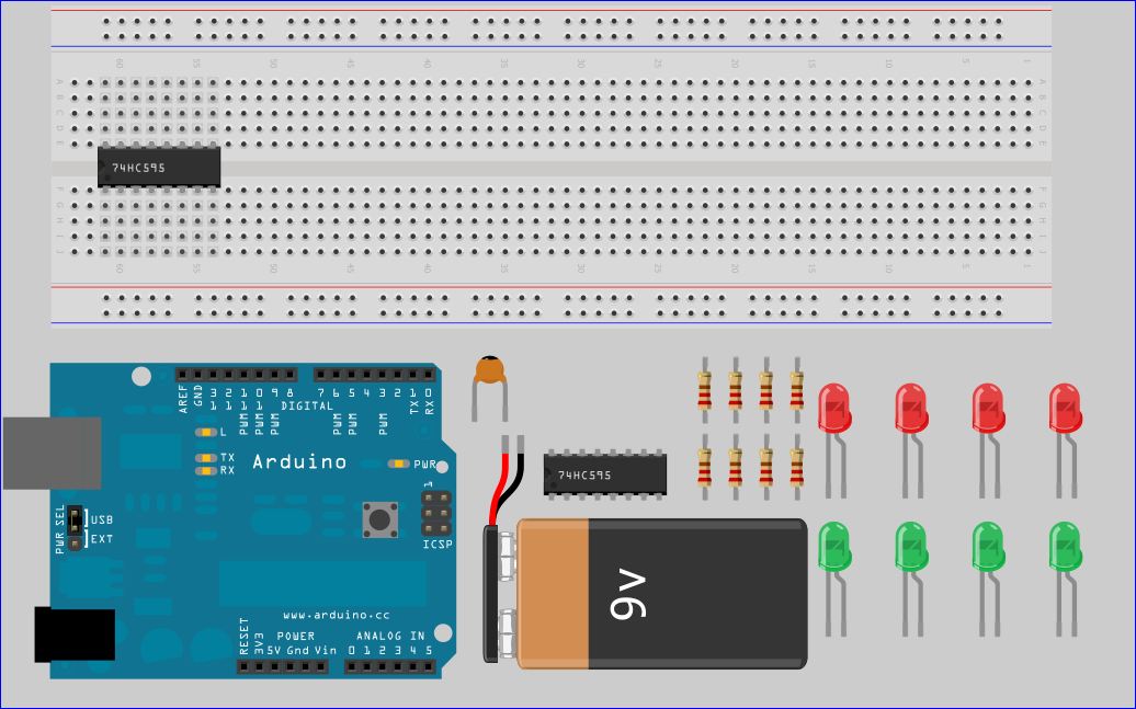
Now place the 74HC595 on the breadboard.
Wire It Up (Part 3)
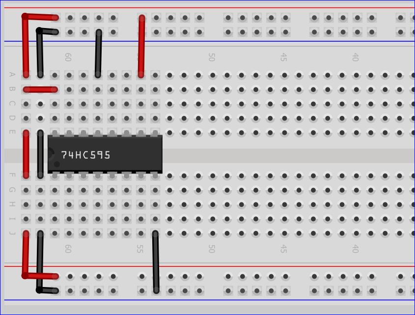
Now insert the wires as shown
Wire It Up (Part 4)
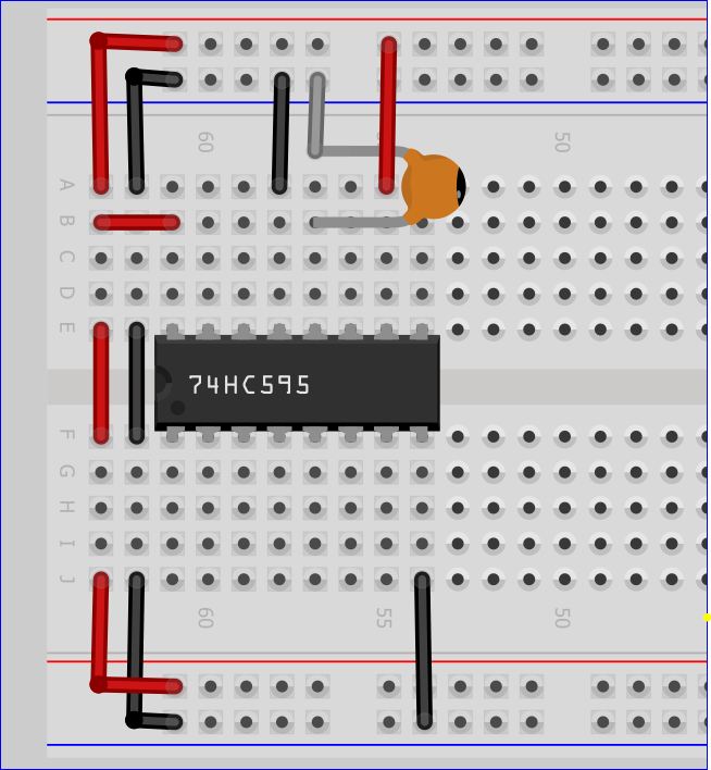
Now add the Capacitor
Wire It Up (Part 5)
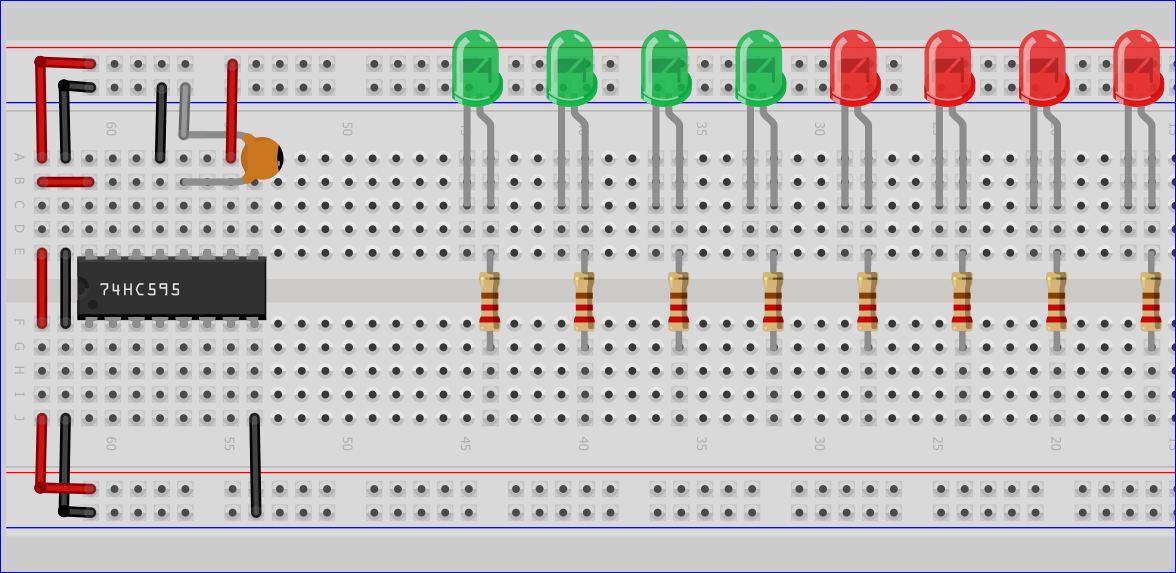
Add the eight LEDs and eight 220 ohm resistors
Wire It Up (Part 6)
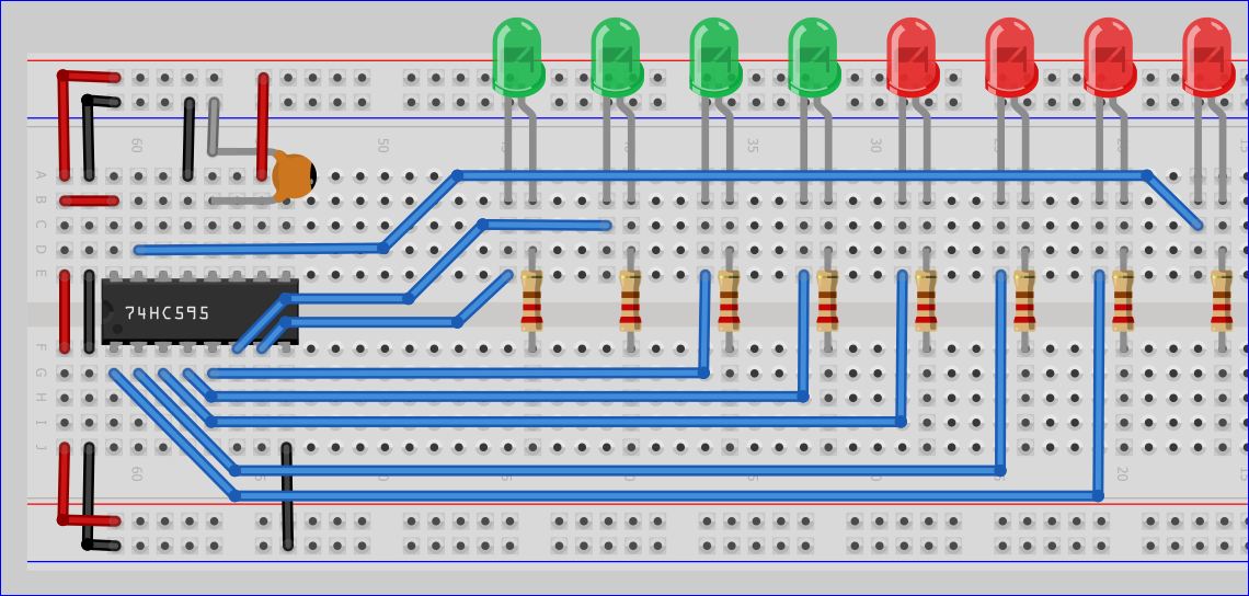
Wire the each LED's anode to pins 15 & 1 to 7
Pin15 = Output_0 // Port_# 1
Pin1 = Output_1 // Port_# 2
Pin2 = Output_2 // Port_# 3
Pin3 = Output_3 // Port_# 4
Pin4 = Output_4 // Port_# 5
Pin5 = Output_5 // Port_# 6
Pin6 = Output_6 // Port_# 7
Pin7 = Output_7 // Port_# 8
Pin15 = Output_0 // Port_# 1
Pin1 = Output_1 // Port_# 2
Pin2 = Output_2 // Port_# 3
Pin3 = Output_3 // Port_# 4
Pin4 = Output_4 // Port_# 5
Pin5 = Output_5 // Port_# 6
Pin6 = Output_6 // Port_# 7
Pin7 = Output_7 // Port_# 8
Wire It Up (Part 7)
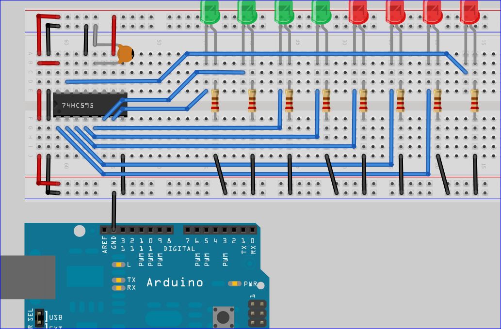
Connect each of the resistors to ground
Also connect your Microcontroller's GND pin to the breadboard's ground
Also connect your Microcontroller's GND pin to the breadboard's ground
Wire It Up (Part 8)
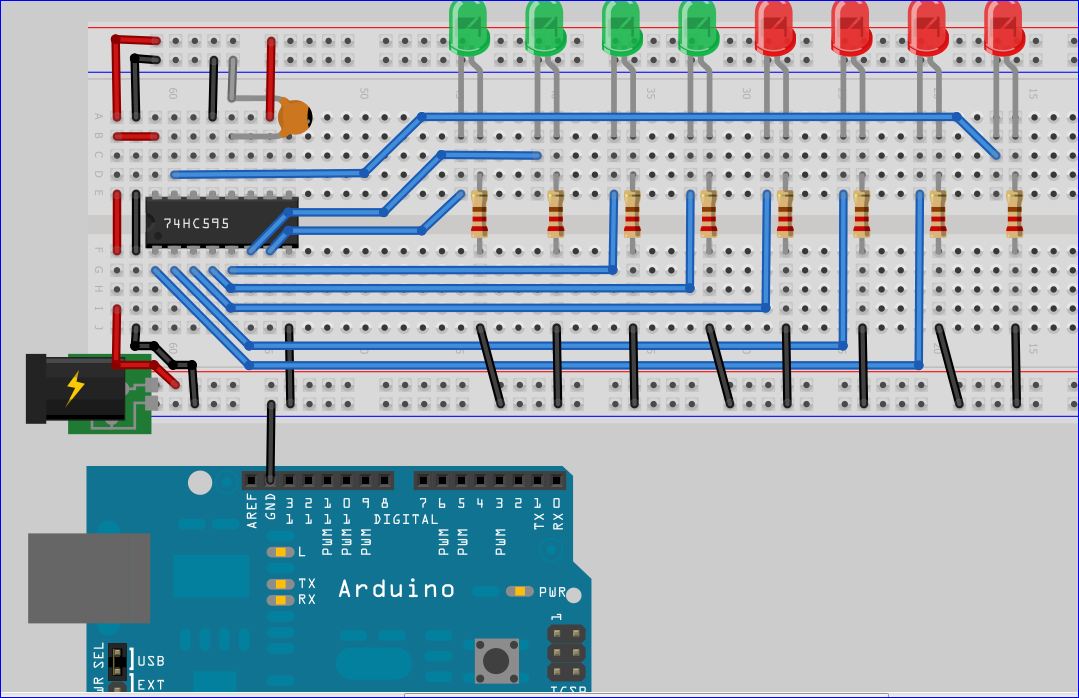
Find your 3 to 5 volt, regulated DC power supply, and connect the Positive connection of the power supply
to the Breadboard's Positive rail.
Next, connect the power supply's Negative connection to the breadboard's negative, or ground, rail.
to the Breadboard's Positive rail.
Next, connect the power supply's Negative connection to the breadboard's negative, or ground, rail.
Wire It Up (Part 9)
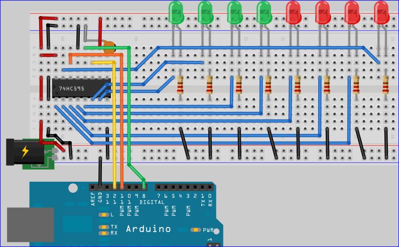
Finally connect the Arduino's 3 digital pins as shown
Code

Below is the code for use with an Arduino
//Pin connected to ST_CP of 74HC595
int latchPin = 8;
//Pin connected to SH_CP of 74HC595
int clockPin = 12;
//Pin connected to DS of 74HC595
int dataPin = 11;
void setup() {
pinMode(latchPin, OUTPUT);
pinMode(clockPin, OUTPUT);
pinMode(dataPin, OUTPUT);
}
void loop() {
for (int j = 0; j < 256; j++) {
//ground latchPin and hold low for as long as you are transmitting
digitalWrite(latchPin, LOW);
shiftOut(dataPin, clockPin, LSBFIRST, j);
//return the latch pin high to signal chip that it
//no longer needs to listen for information
digitalWrite(latchPin, HIGH);
delay(1000);
}
}