How to Use a Photoresistor to Light an LED With Aurduino
by SimplyMacy in Circuits > Arduino
811 Views, 0 Favorites, 0 Comments
How to Use a Photoresistor to Light an LED With Aurduino
Good morning/afternoon/evening to all you Arduino-enthusiasts! Today, I'm going to be demonstrating how to use a photoresistor (photocell) to light an LED. The code provided with this Instructable will let the LED sit dim normally, but will blink when the light is blocked from the sensor. So get a nice glass of water (a safe distance away from your workspace) and let's get to it!
What You'll Need
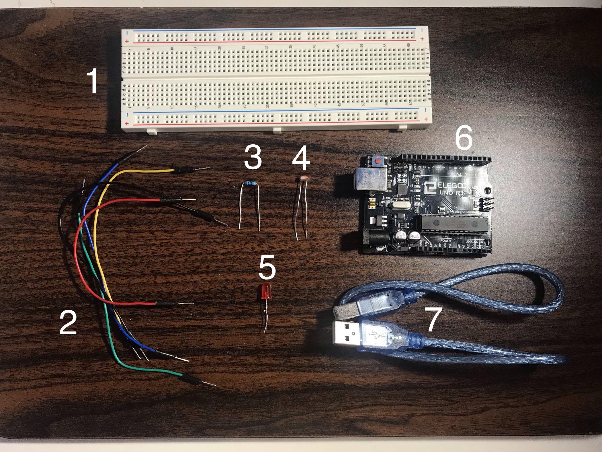
First, of course, you'll need a computer with the Arduino program, which you can download here! The materials you need can be found in the Super Starter Kit UNO R3 Project that you can find when you click here! The materials you'll need out of that box go as follows:
1. Breadboard
2. Male to Male Wires (x5)
3. 10kΩ Resistor (x1)
4. A photoresistor (or photocell) (x1)
5. Any colored LED (x1)
6. The UNO R3 Controller Board
7. USB Cable
Optional: Pliers (this will be to help insert the pieces into the breadboard if you have trouble with it like me)
Our First Move! the LED
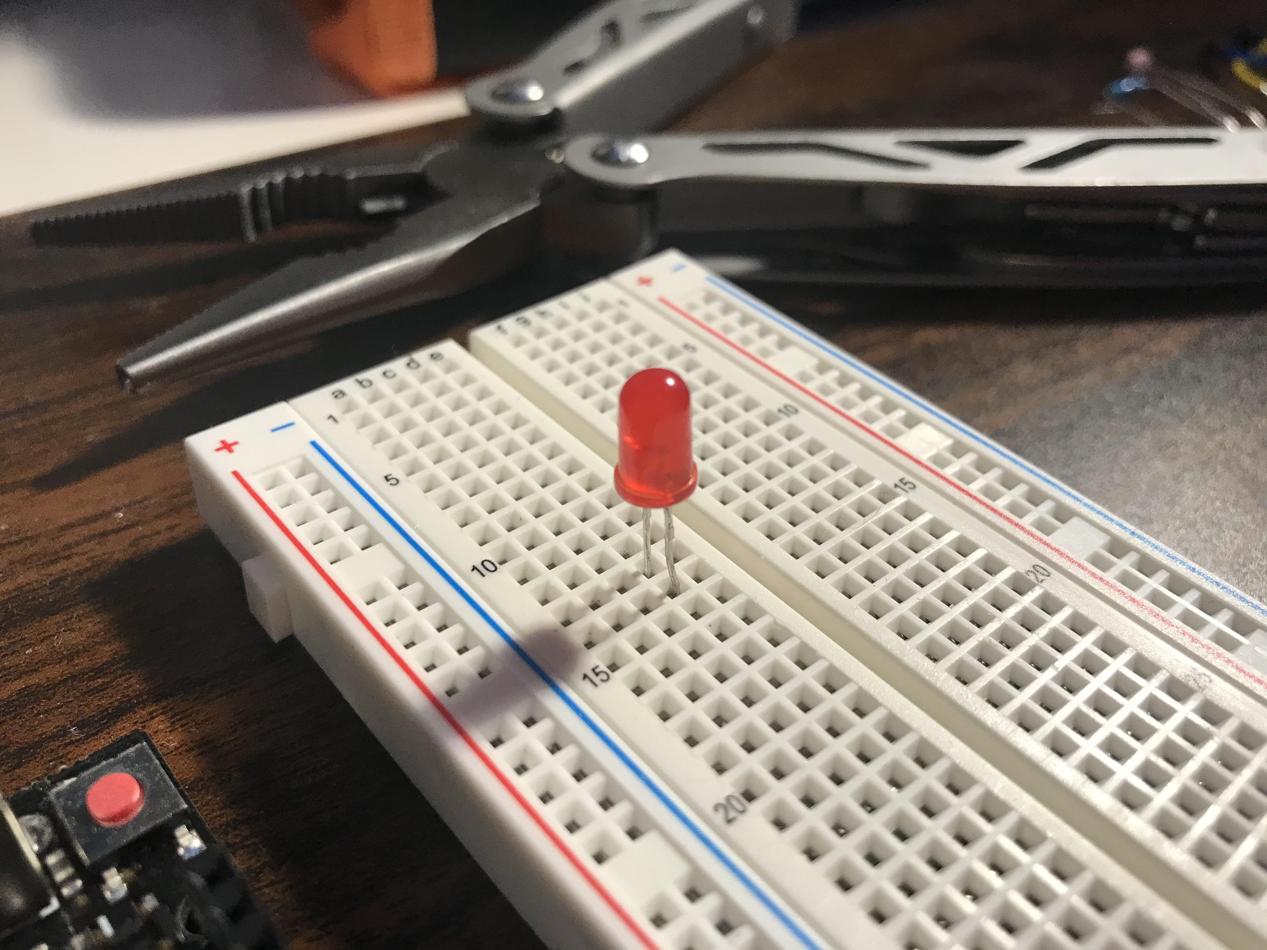
Place the LED in your breadboard like so. Make sure the flat side is facing away from you.
The Resistor
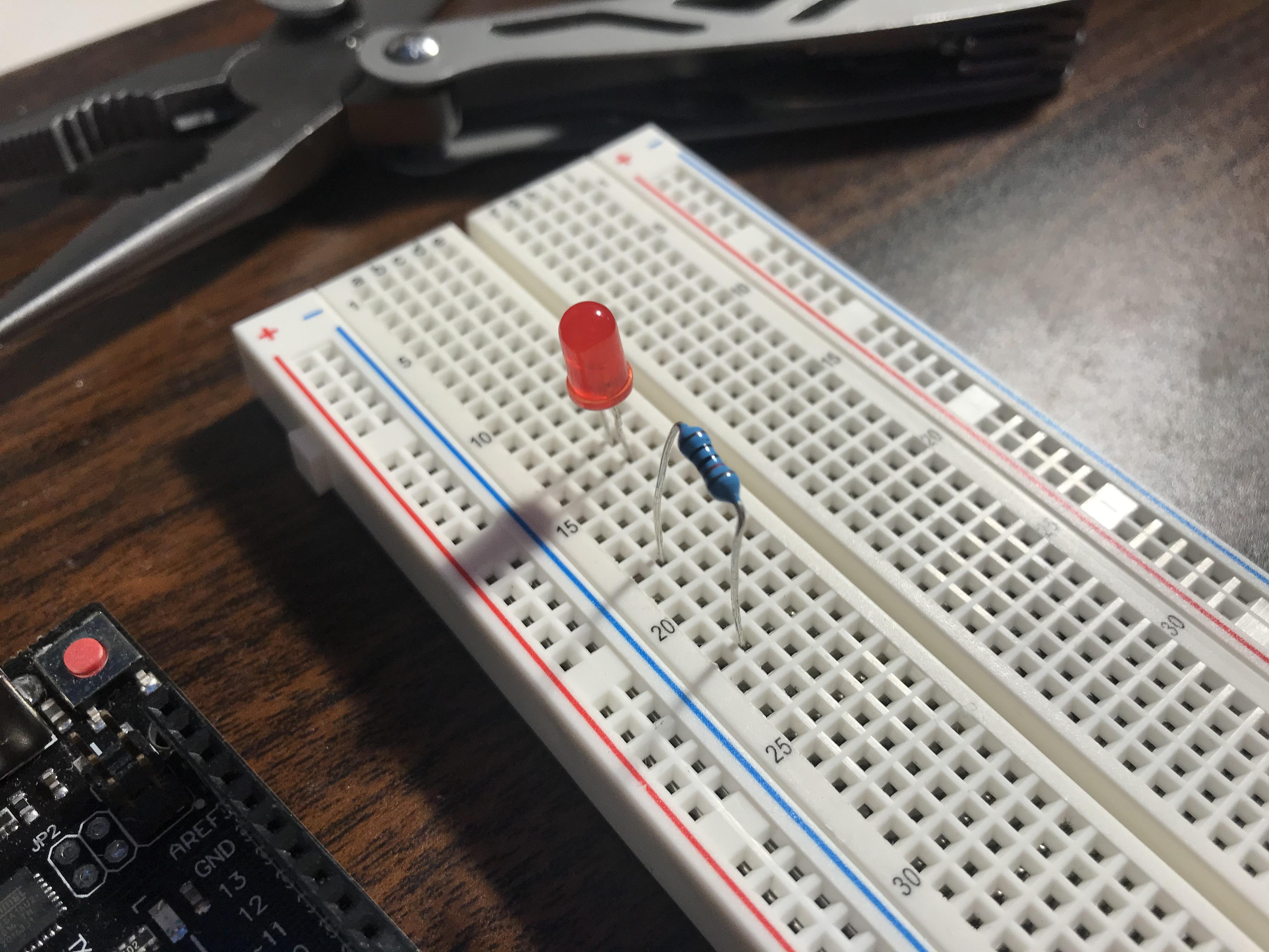
Place the resistor on the board like so, so it may join its little LED friend. The resistor doesn't have to be in a certain direction.
The Photoresistor (Photocell)
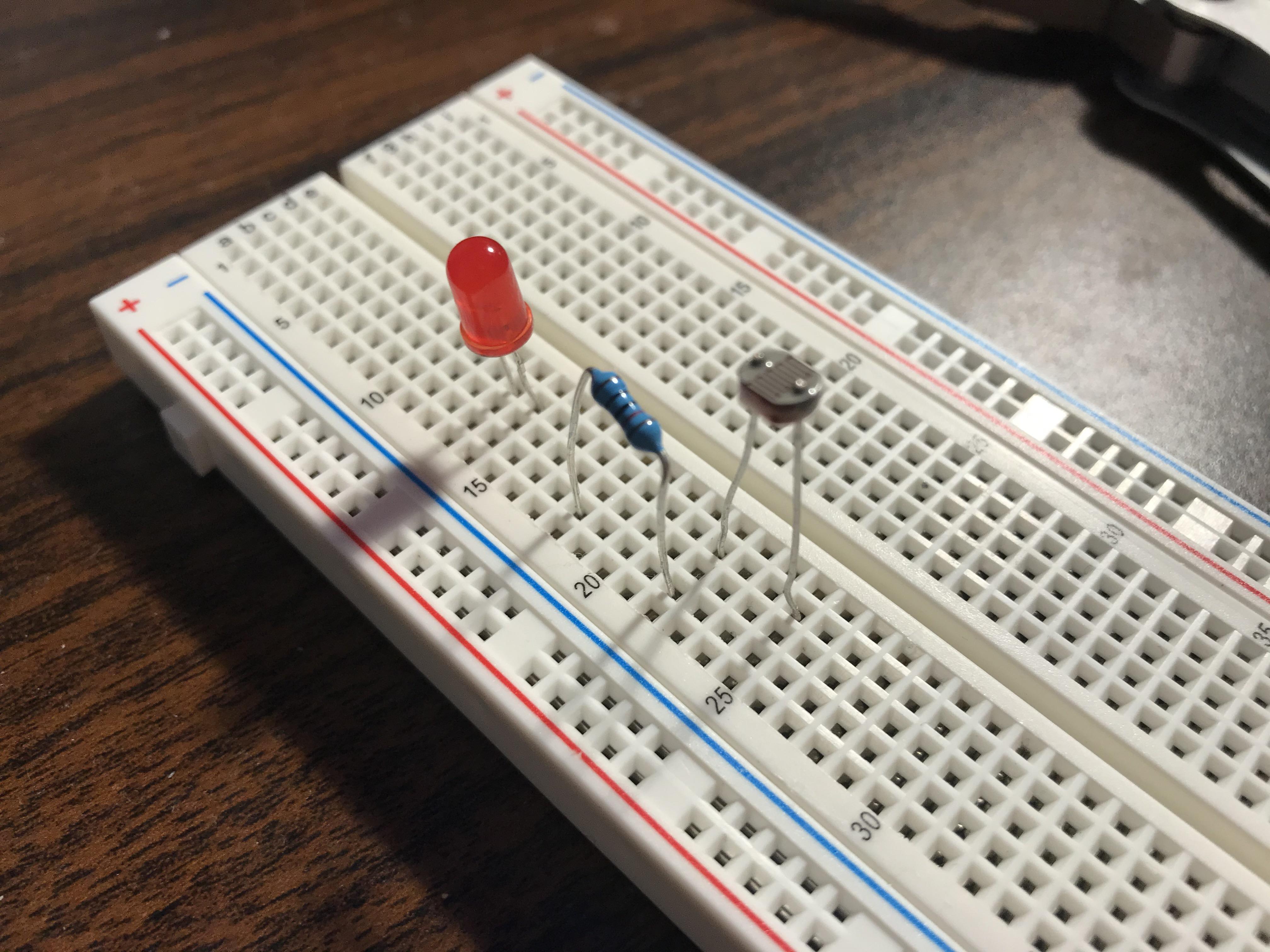
Place the photocell as such, so one leg is in the same line with the closest leg of the resistor. They're good friends, but they don't really hang out that much outside of the workplace, you know?
Grounding the Board
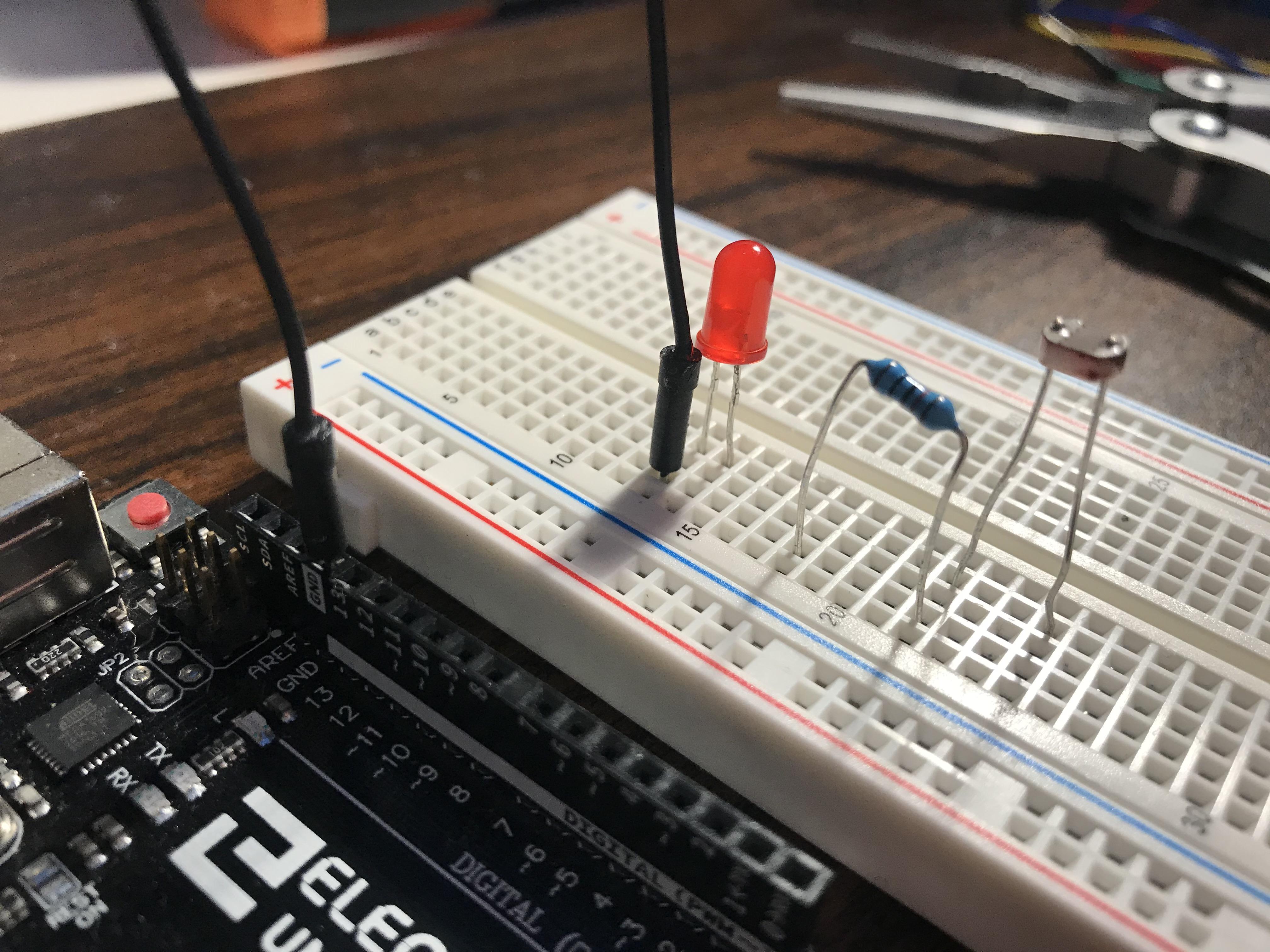
Take one of your Male to Male wires and your UNO board and ground the negative side of the LED to the GND port, next to the 13.
The Second Wire: the Clone Wars
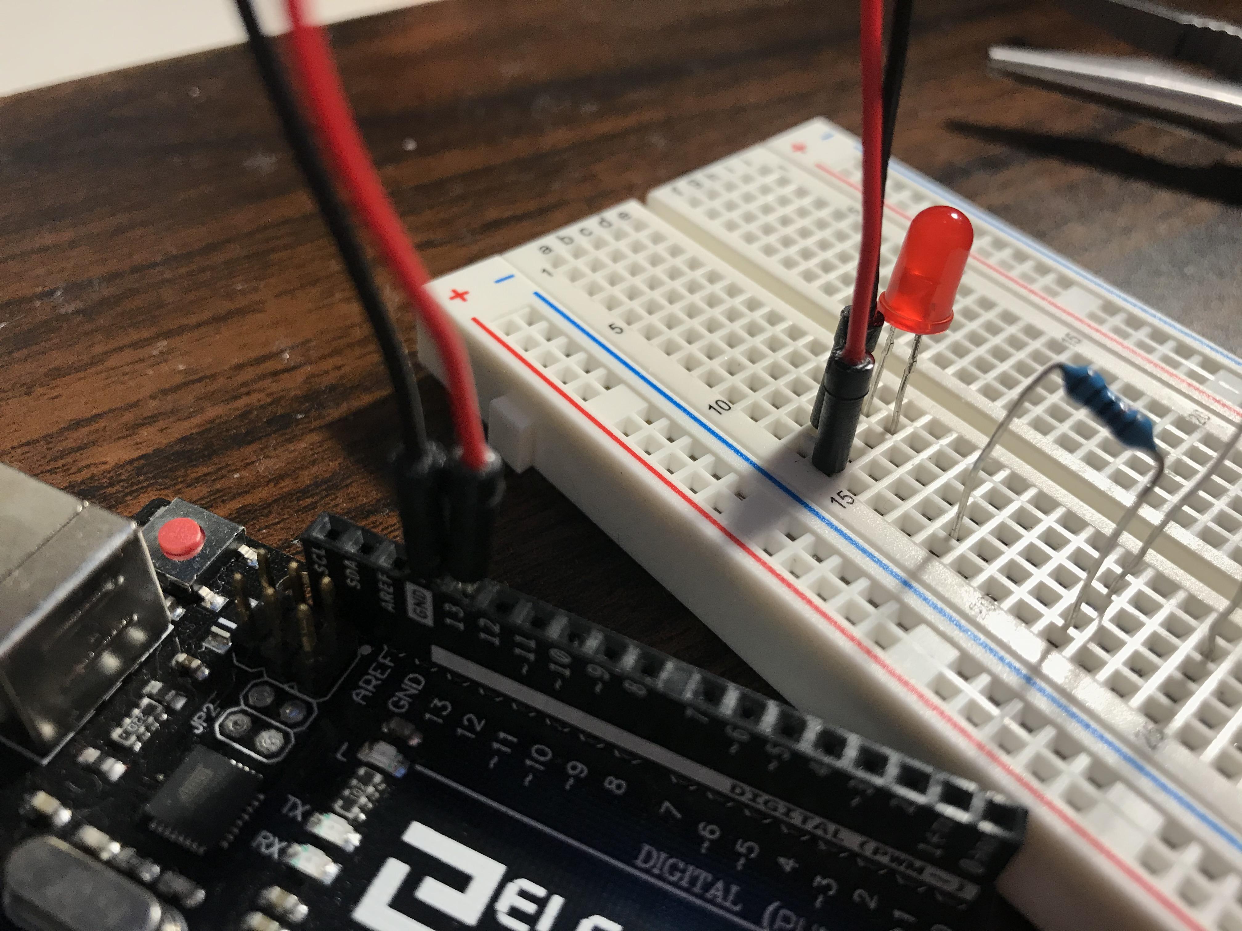
Take your second Male to Male wire (preferably a different color) and ground the positive side of the LED to the 13 port, so your two wires are ACTUALLY close buddies and could go grab a coffee or something.
Wire 3: Revenge of the Sith
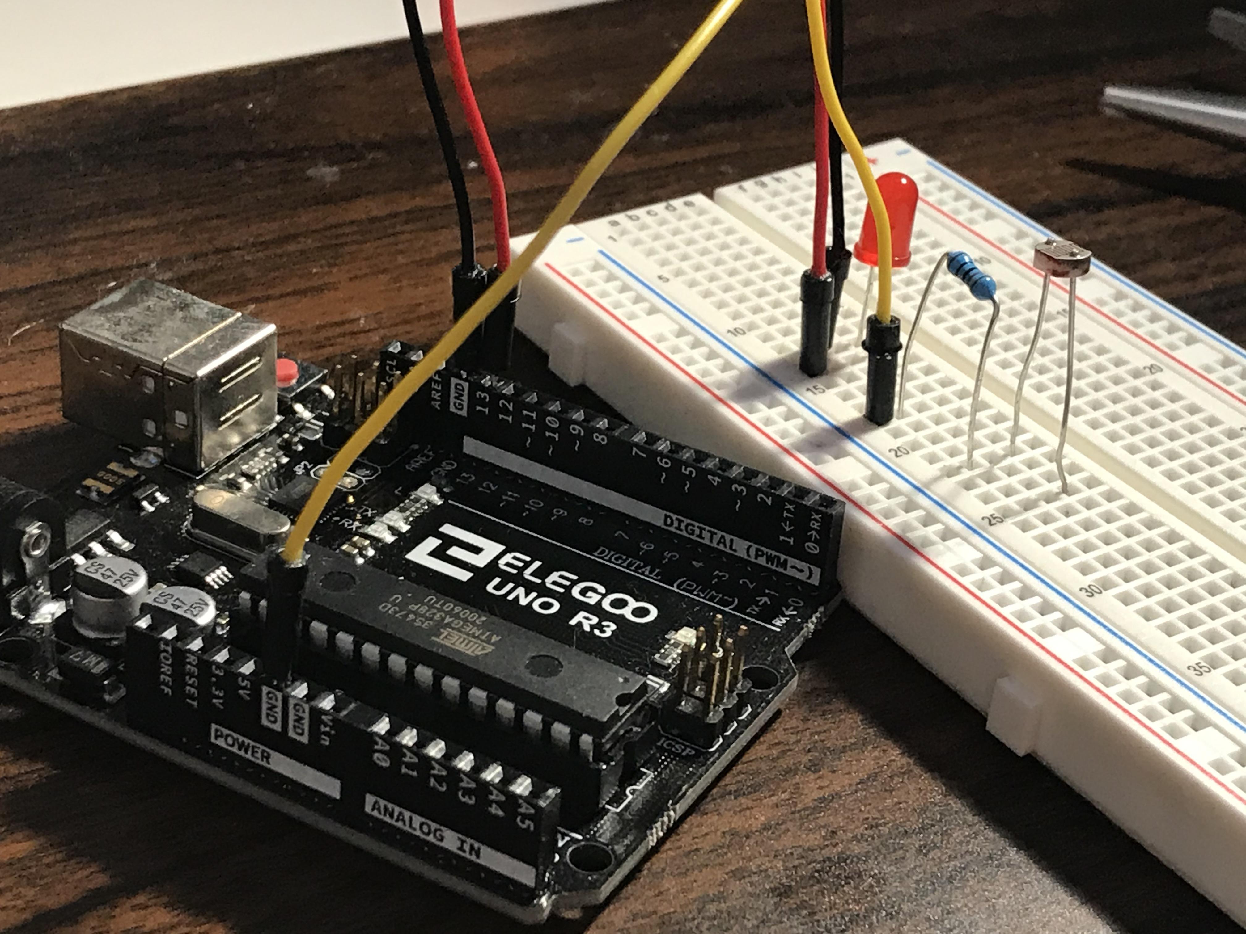
Take another Male to Male wire (again, a different color) and ground one side of your 10kΩ resistor and connect the other side to the GND port, right next to 5V.
Wire 4: a New Hope (the Best One)
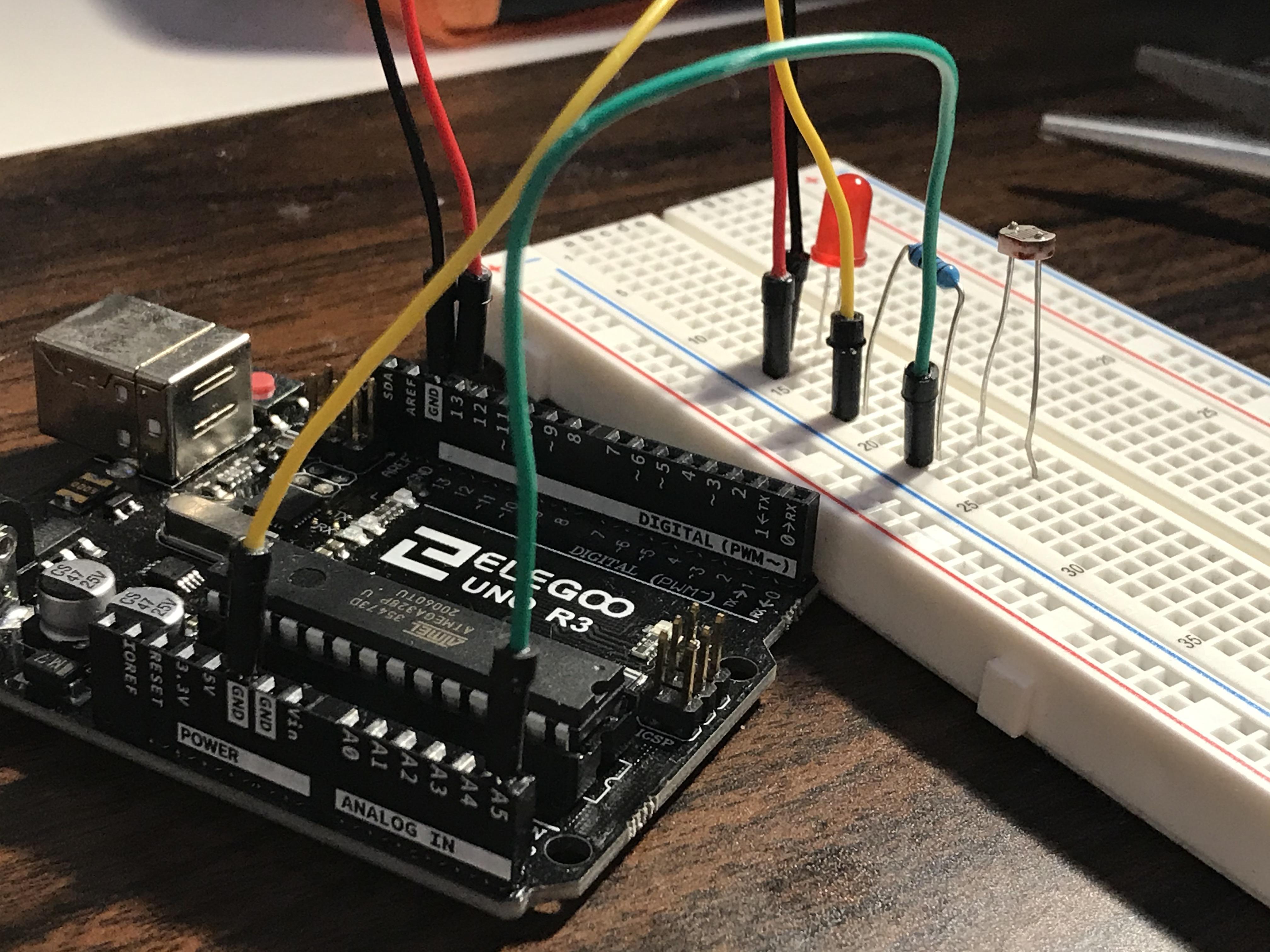
Take another wire (honestly if all of your wires are the same color, you're a psychopath, pal) and ground the other side of the 10kΩ resistor and one side of the photocell and connect the other end to the A5 port on the end of the UNO board. So wires 3 and 4 are just long distance friends.
Wire 5: Return of the Jedi
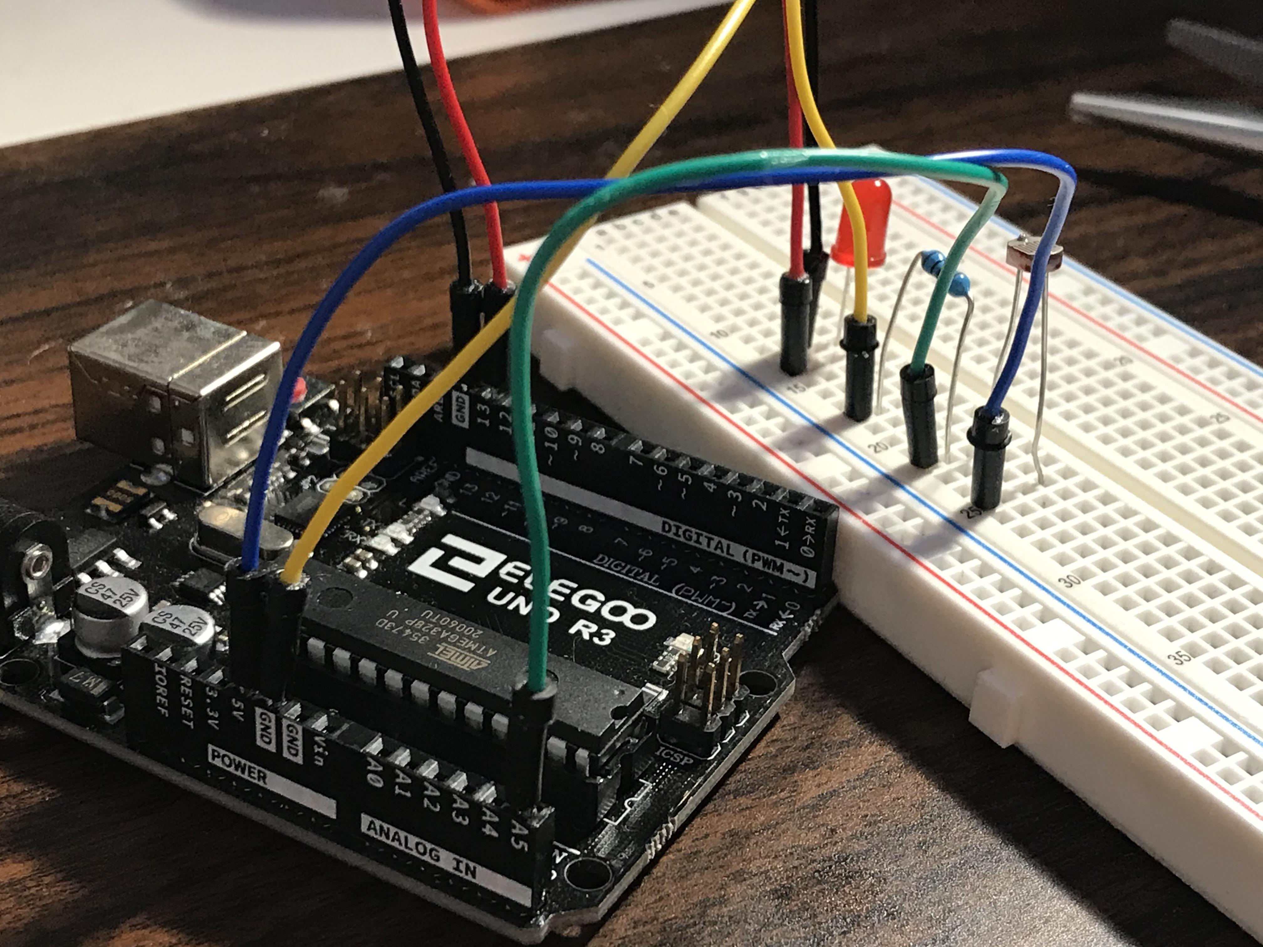
Take your LAST Male to Male wire and ground the other end of the photocell and connect the other end of the wire to the 5V port, right next to Wire 3. They should double date with wires 1 and 2! <3
A Quick Overhead Shot
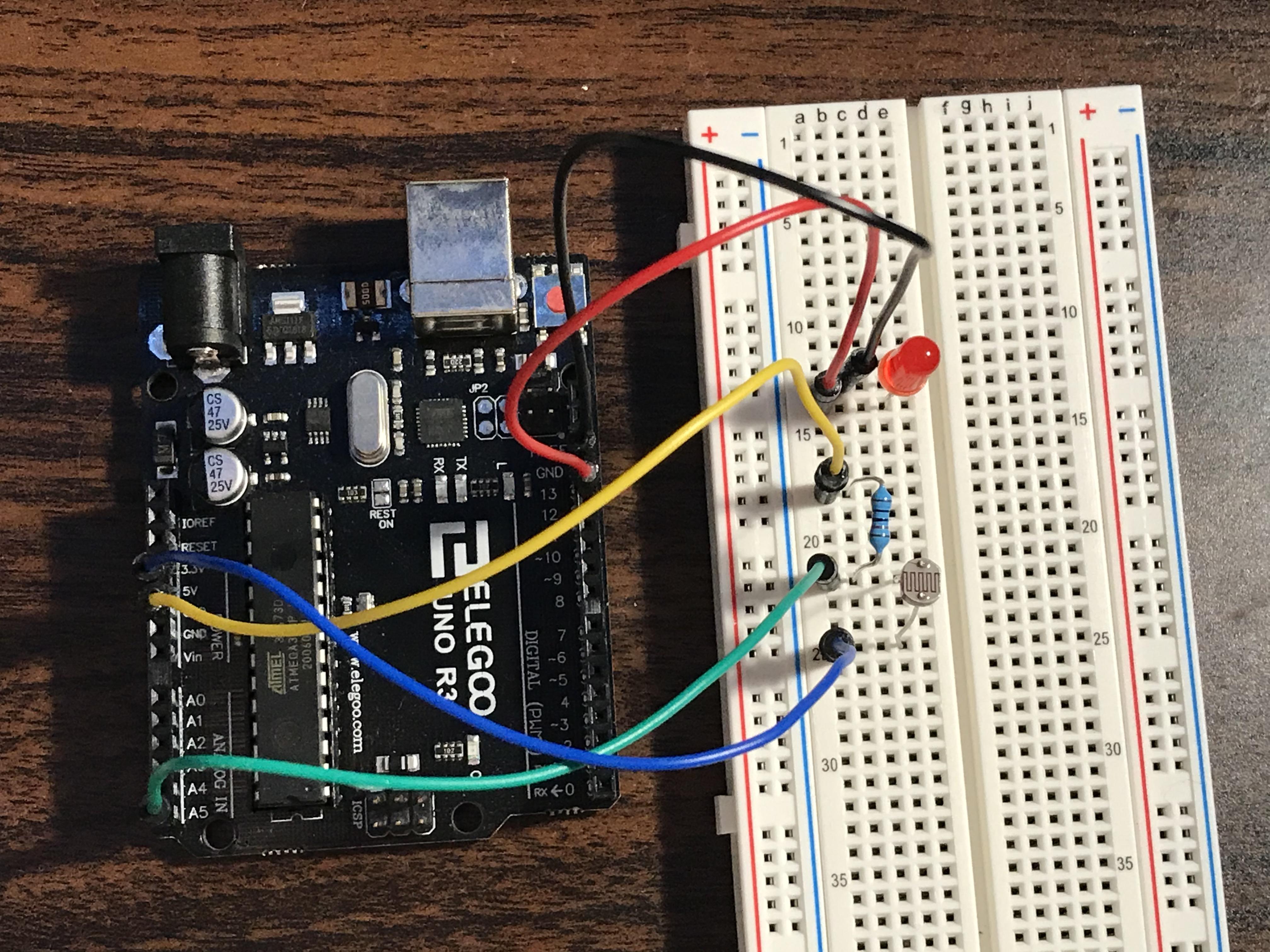
This is about what your board should look like from a top perspective.
The Arduino Code
Download the code provided! Plug in your Arduino board using your USB cord and upload the sketch using the arrow at the top. Then watch the video below for the demonstration on how the final product should look!
Downloads
The Final Frontier
This video shows the board in action and additional tips to make sure your board is working. Thanks for listening and I hope you enjoyed!