How to Use a PIR Motion Sensor With Arduino
by KEB05 in Circuits > Arduino
23215 Views, 5 Favorites, 0 Comments
How to Use a PIR Motion Sensor With Arduino
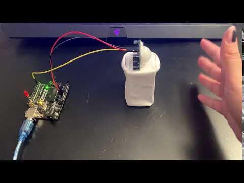
I ordered a PIR motion sensor recently and thought it would be easy to set up. However, I found that I only became more confused looking up many online tutorials that suggested different things to try. I want to test my ability to code a motion sensor to blink a specific way while also providing an easier tutorial all in one place. This is my process of making a LED react with a motion sensor.
Supplies
ELEGOO UNO Project Super Starter Kit with Tutorial and UNO R3 Compatible with Arduino IDE - $36.99
This Starter Kit comes with everything you would need to get started with making circuits for future projects. It is costly but worth it for all that is included in the kit.
What you need from the Starter Kit:
- ELEGOO UNO R3
-1 LED
-3 Male to Female Jumpers
-USB Type A to B Cable
Motion Sensor - $8.99
The motion sensor is not included in the Starter Kit so you must buy it separately. You will only need to use one for the project.
Phillips head screwdriver - $5.90
There is one step where a screwdriver is needed. Make sure to have one around before starting.
Total: $51.88
Setting Up the Circuit
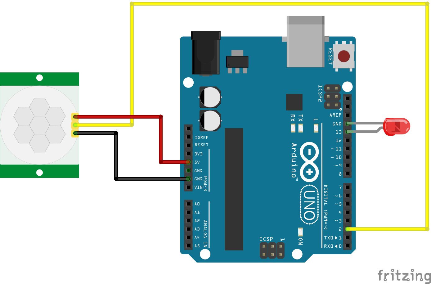
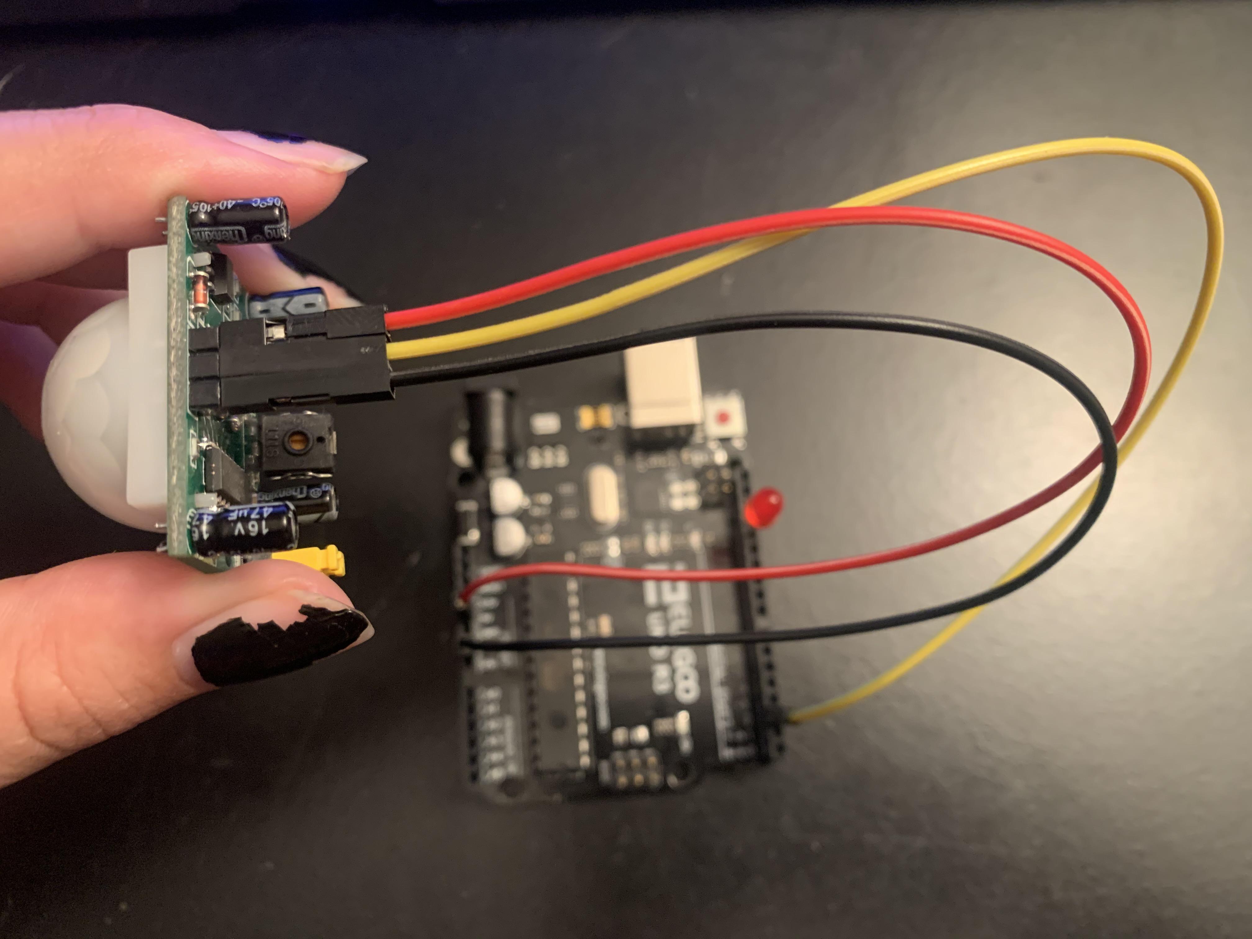
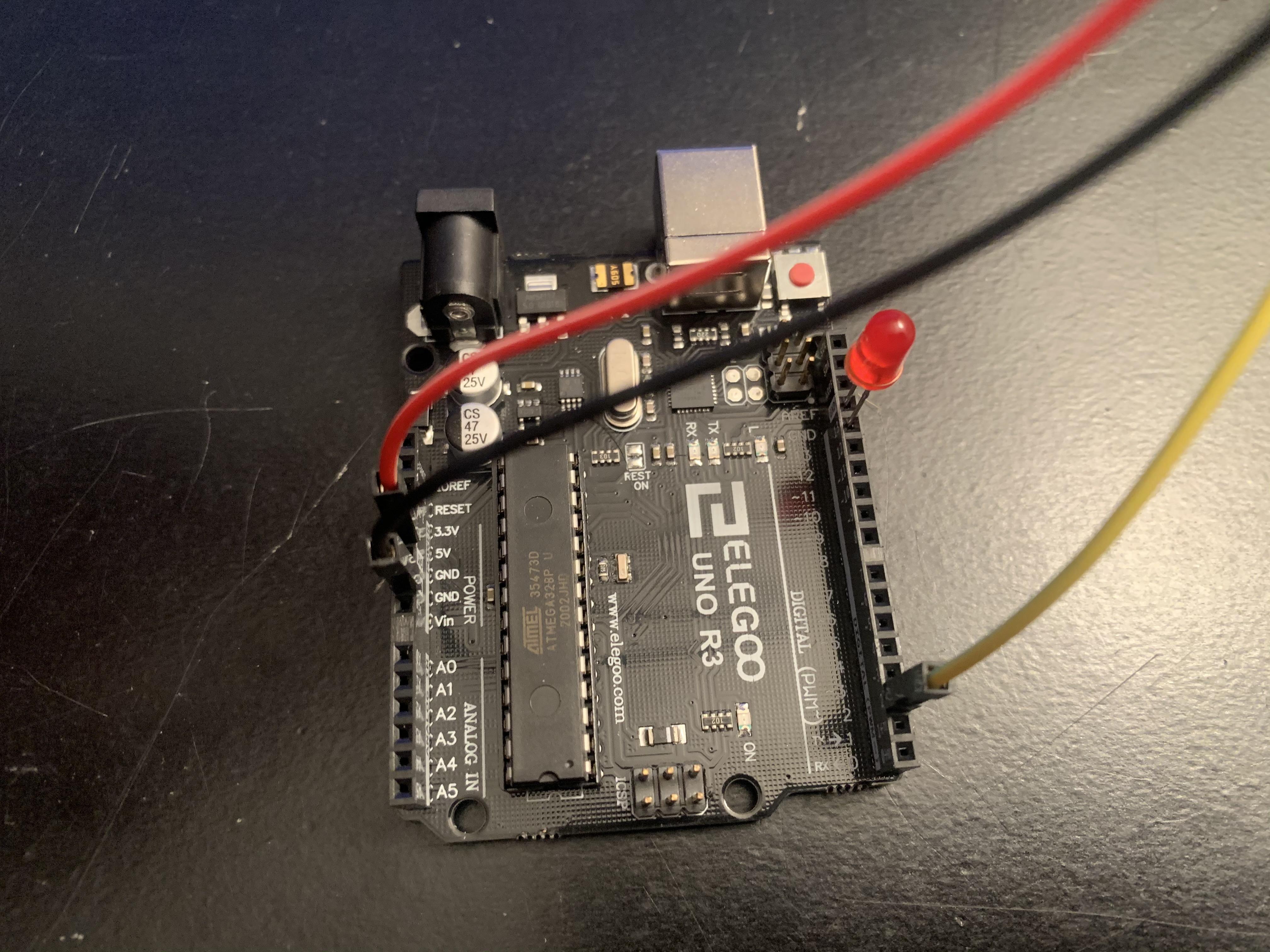
To begin this project, I started with setting up the ELEGOO UNO.
I've included a photo and file of the Fritzing diagram to follow along. This was inspired from a tutorial in Arduino Project Hub to get the basic understanding of how to code a PIR sensor.
- For this prototype, I kept the LED on the UNO in Pin 13 and ground (Remember: Short leg goes in ground; long leg goes in Pin 13).
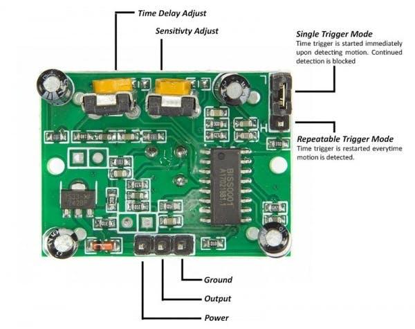
- To connect the PIR Sensor to the UNO, I used the male to female jumpers. Power goes to 5V; Output goes to Pin 2; Ground goes to Ground (Refer to PIR Sensor Diagram).
IMPORTANT NOTE: Make sure to have the power and ground connected correctly on the sensor! I accidentally swapped then when I first tested the sensor. The second image diagrams all the parts of the PIR sensor.
Downloads
Setting Up the PIR Sensor
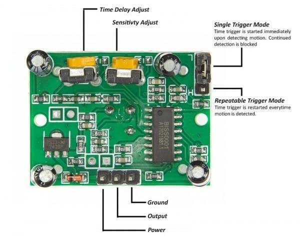
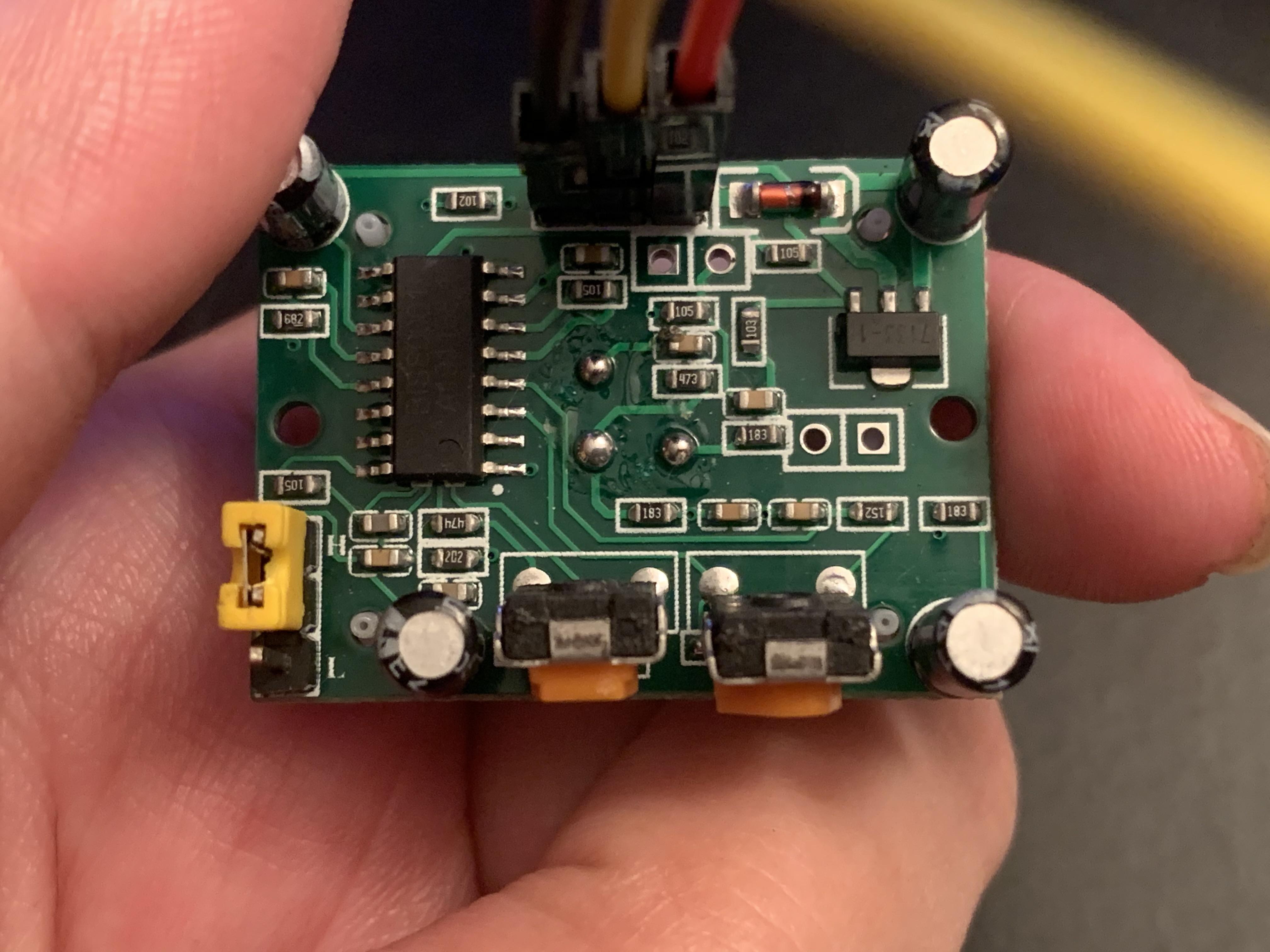
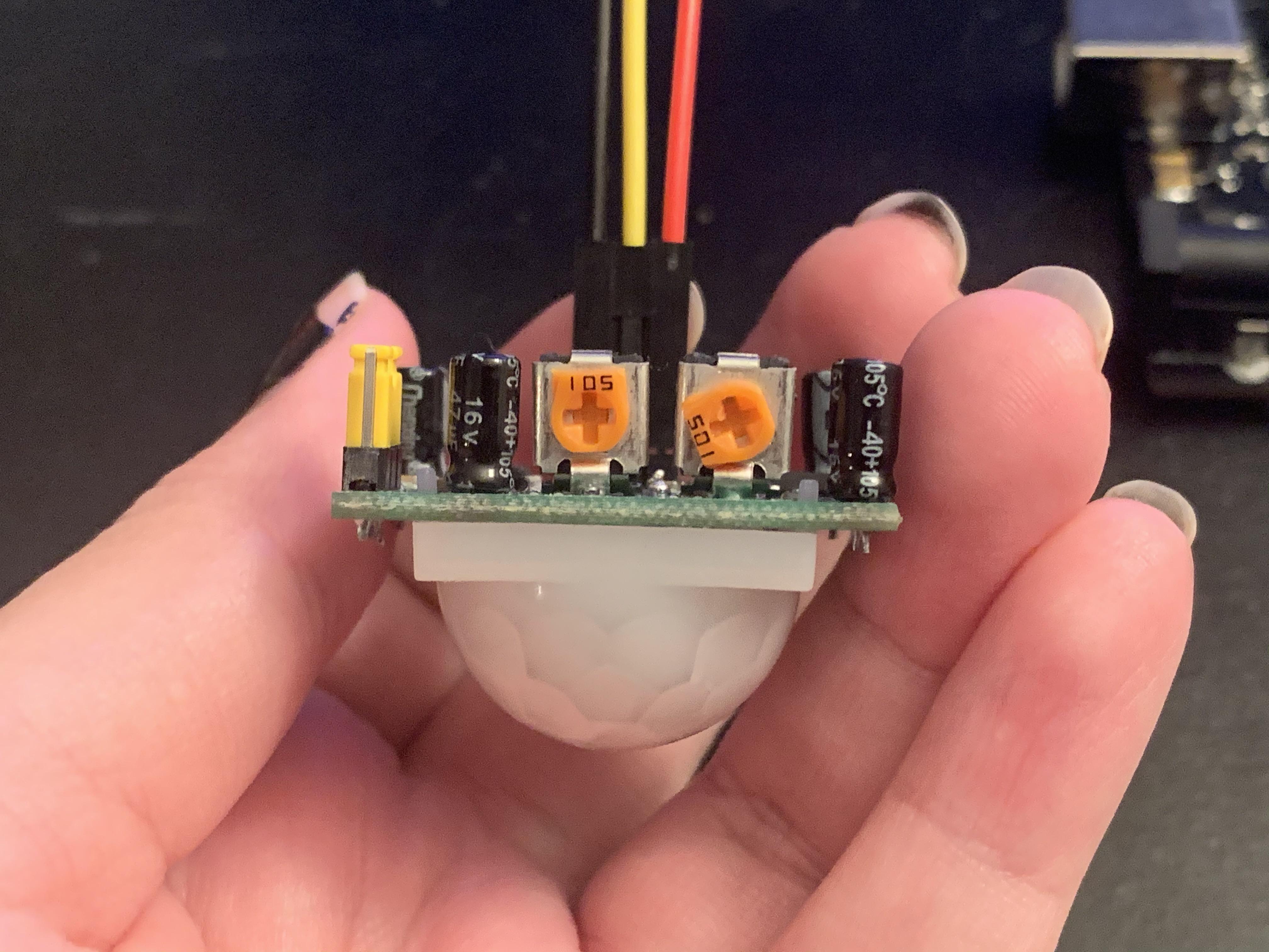
The PIR sensor can be adjusted manually by looking at the back. I had to make some slight adjustments to make the sensor more reactive before I got too far into the coding process. I used an article from Tweaking4All.com to learn more about how to adjust the "settings" of a PIR sensor. Another helpful website that explains the "settings" of the PIR sensor is adafruit.com (This website gives a little more details with photos).
- The first part is adjusting the Trigger Mode from low to high. It is a small jumper in the top right corner of the sensor labeled with L and H (as seen in the PIR diagram). Reasoning: If it was on Single Trigger Mode (Low), the LED would turn off after a few seconds even if there was continued motion. In Repeatable Trigger Mode (High), the LED will stay on with continued motion and turn off when there is no motion detected.
- Next, decrease the Time Delay to its lowest setting. I want the sensor to react as fast as it can to when the motion stops. The lower the setting; the faster the light will turn off. Remember: Clockwise to increase; Counter-clockwise to decrease. Also the lowest setting will still have approximately a three second delay.
- Optional: Increase the Sensitivity. The sensitivity controls the distance the sensor will detect motion. This part is really just preference. I am fine with having the sensitivity to be in the middle, but in the future I may mess with it more.
Basic Test of the Sensor
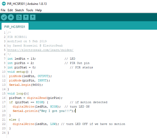
After all that set up, I use the code that the Arduino Project Hub tutorial gives to test if the sensor is working correctly. (I've included a copy of the code in this step)
When I upload the code, I give the sensor about 15-30 seconds to calibrate before testing motion.
The main thing to look for in this test is:
- Does the sensor react if you move your hand in front of it? (If not, check if the sensor is connected properly or if the sensitivity is too low)
- Does the LED stay on if you keep waving your hand in front of the sensor? (If not, check if the jumper is on high for Repeatable Trigger Mode)
- Is the LED delay time only a few seconds when there is no motion detected? (If not, make sure that Time Delay is on the lowest setting)
Important Note: I read in a lot of tutorials that the LED light will stay on until the sensor is done calibrating, but the only time the LED was on when I uploaded the script was when I had the power and ground connected to the wrong pins. For my sensor if connected properly, the LED will stay off when the script is uploaded and was the only time that it would detect motion properly.
Downloads
Setting Up the Final Code
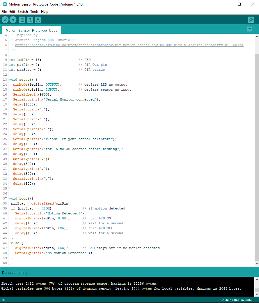
Once I was able to test my motion sensor, I wanted to try to take the previous code a step further and give it a rapid blink command when it detects motion. Also I did not like what the Serial Monitor was scripted to print, so I will make an updated version to that as well. (Copy of final code in this step)
What was added:
- Blink Command
- Updated Version of Serial Script
The blink command is programing the LED to turn on and off using the "delay" command. Setting a delay works by the millisecond (Example: 1000 m/s = 1 second). I was not happy with the one second delay so I reduced the time to 100 m/s.
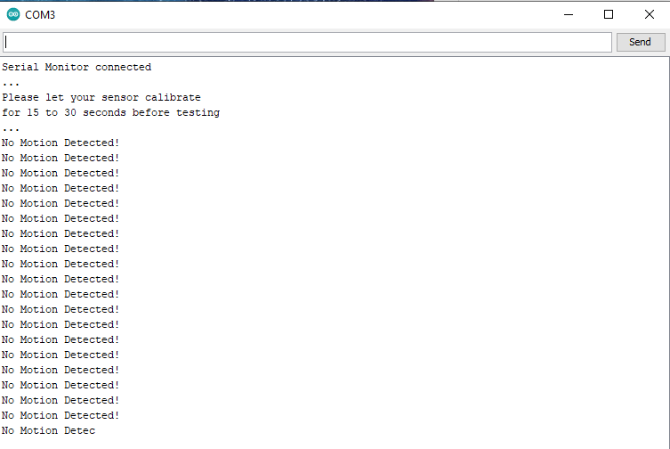
The serial monitor script took a little bit longer to code in the set up. I wanted to have a message that pops up when the serial monitor is opened in the set up. Also, I included a message that updates with the constant state of the sensor. When scripting a serial monitor remember the commands "Serial.begin(9600)", "Serial.print()", and Serial.println()".
Note: I did find an example code where there is a way to only have the monitor react to the output change and not the state change. If you are interested in that, Ada Fruit has a copy of their code in this article. It makes the serial monitor more cleaned up, but it also involves adding more variables and if statements. For that reason, I kept it out of this tutorial to keep things simple for others to understand. However, for future projects I would recommend adding this to the code.
Downloads
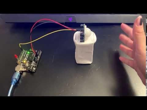
Testing the Prototype
Once I put all the steps together, I made a working motion sensor prototype. The nice thing with this final code is I can keep track of what the sensor sees in the serial monitor, and I can make any adjustments on the sensor without having to make changes in the code. I feel like I have a much better understanding of how the PIR sensor works. I hope that this tutorial is helpful for others.