How to Use RTC Module With Arduino
by Eli S in Circuits > Arduino
1641 Views, 2 Favorites, 0 Comments
How to Use RTC Module With Arduino
.png)
.png)
this tutorial will teach you how to connect code and use a RTC module with Arduino. if you have any questions, please feel free to post a comment and I will probably be able to help you out! now grab your RTC and let's get started!
Supplies
Martials Needed:
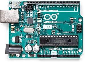
1: Arduino uno board - you can use uno or mega, but nano won't work. link: Amazon.com: ELEGOO UNO R3 Board ATmega328P with USB Cable(Arduino-Compatible) for Arduino : Electronics
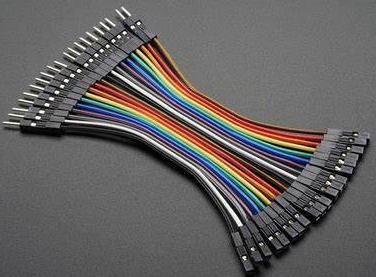
2: F-M jumper wires - for connecting RTC to Arduino board. link: Amazon.com: Hellotronics Breadboard Jumper Wires 22AWG, Pack of 120 Female to Female More Red and Black Jumpers, Square Head 0.1'' 10 Colors (15CM, F/F-Black60, Red60) : Electronics
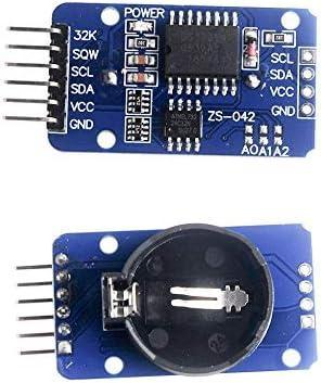
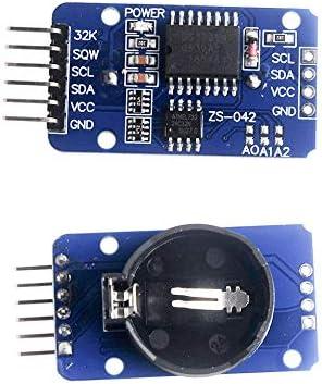
3: RTC module - what we're learning about today. link: Amazon.com: DS3231 DS3231SN AT24C32 IIC Module Precision RTC Real Time Clock Memory Module 3.3-5 .5V for Arduino : Electronics
Tools needed:
1: desktop or laptop computer - any brand will work, but no mobile devices.
What Is an RTC Module?
.png)
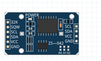
RTC modules are a small modules that keep time precisely by use of a built-in battery and are used in electronics to keep time even when the device loses power. RTC stands for real time clock. the module has 6 pins on one side, and 4 pins the other side. we will talk more about the pins when we get to connecting it. we can use RTC modules to make a variety of useful projects such as a lcd clock, alarm clock and more. now, let's move on to connecting it to Arduino!
Connecting
.png)
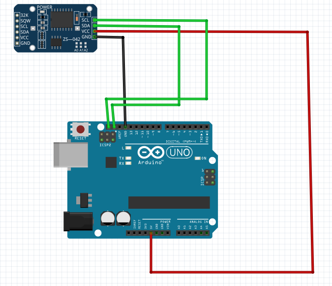
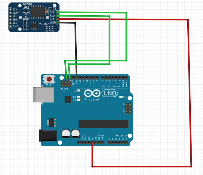
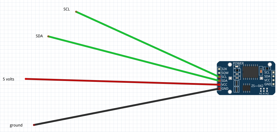
so, for connecting the RTC module to the board, we first need to learn the pins. your RTC has 1 set of pins on one side, and a different set of pins on the other side. one set of pins has more than the other side, this is the side we will connect from as the other side does not have pin headers pre-soldered. (otherwise, we would use that side) it has 6 pins, 4 of which we will use. the first pin we will be using is the vcc pin. this pin will connect to a 3.5-5 volt power source. the next pin we will use is the gnd pin. (gnd stands for ground) this pin will get connected to a ground source. next is the SDA pin, this is one of two communication pins, and it will be connected to SDA on the Arduino board. the last pin we will use is the SCL pin. this is the second of the two communication pins and will get connected to the SCL pin on the Arduino board. to connect the RTC module to the Arduino board, you can use the provided schematic above, or use the written guide below.
vcc on module to 5v on Arduino board (it could go to 3.3v to)
gnd on module to gnd on Arduino board
SDA on module to SDA on Arduino board
SCL on module to SCL on Arduino board
Coding
.png)
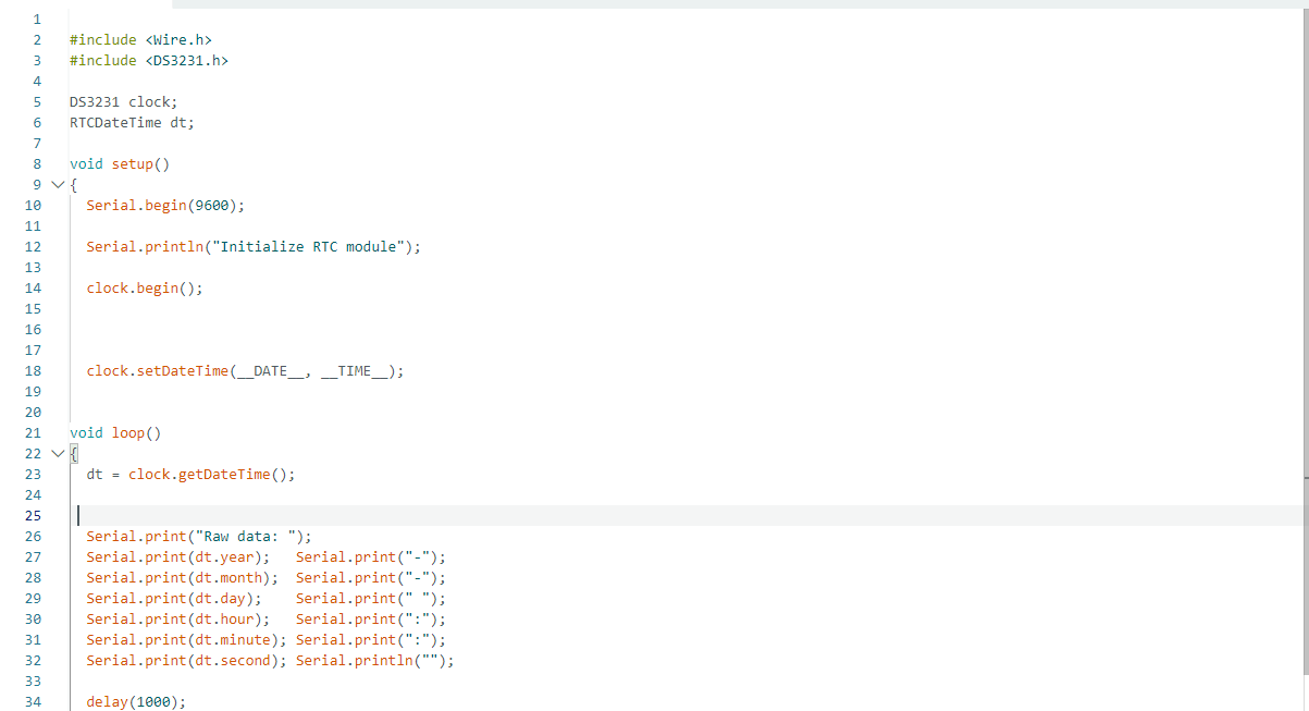
now it's time for the coding. we will need to download the RTC library for the code to work. download the libra from the Arduino website here: RTClib - Arduino Reference. then open Arduino and clock on sketch at the top, then library's and then add .zip library. then find the .zip folder you downloaded and select it. ok, so now that you've got the library installed, it's time to write the code. I have it written below, so copy and paste it into your Arduino, and then I'll explain it.
#include <Wire.h> //includes the wire.h library
#include <DS3231.h> // includes the RTC libray
DS3231 clock;
RTCDateTime dt; // initializes the RTC
void setup()
{
Serial.begin(9600); // starts the serial monitor at 9600 baud
Serial.println("Initialize RTC module"); // prints "Initialize RTC module" in serial monitor
clock.begin(); // starts the clock
clock.setDateTime(__DATE__, __TIME__); // initializes the clock
}
void loop()
{
dt = clock.getDateTime(); // reads the data from the RTC module
Serial.print("Raw data: "); // prints "raw data" in the seral monitor
Serial.print(dt.year); Serial.print("-"); // prints the year in serial monitor
Serial.print(dt.month); Serial.print("-"); // prints the month in serial monitor
Serial.print(dt.day); Serial.print(" "); // prints the day in serial monitor
Serial.print(dt.hour); Serial.print(":"); // prints the hour in serial monitor
Serial.print(dt.minute); Serial.print(":"); // prints the minute in serial monitor
Serial.print(dt.second); Serial.println(""); // prints the second in serial monitor
delay(1000); // a delay of 1000 milaseconds (1 second) before the loop repeats
}
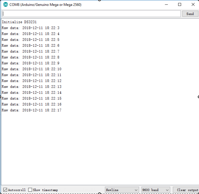
ok, so the first line includes the wire.h libray. which improves communication. the next line includes the RTC libray, which allows communication between the RTC module and the Arduino board. next under setup, we start the seral monitor at 9600 baud. the rest of the code in setup is to initialize the RTC module. next under loop, we read the data from the RTC module, and then print all the data in serial monitor. finally, a delay of 1000 waits one second before repeating the above.
All done! now you know how to connect, code, and use a RTC module! hope this was helpful, and feal free to comment if you have any questions.