How to Use MAX6675 Thermocouple Module & TM1637 LED Display With Arduino
by RonFrtek in Circuits > Arduino
404 Views, 1 Favorites, 0 Comments
How to Use MAX6675 Thermocouple Module & TM1637 LED Display With Arduino

In this tutorial we are going to learn how to use MAX6675 Thermocouple Module & TM1637 LED Display to Display a temperature measured with the probe sensor.
What You Will Need


- Arduino UNO (or any other Arduino or ESP)
- Thermocouple Thermometer MAX6675 module with the sensor
- TM1637 LED Display
- Jumper wires
- Visuino program: Download Visuino
The Circuit

- Connect LED Display pin[CLK] to Arduino digital pin[8]
- Connect LED Display pin[DI0] to Arduino digital pin[9]
- Connect LED Display pin[GND] to Arduino pin[GND]
- Connect LED Display pin[VCC] to Arduino pin[5V
- ]Connect Thermometer MAX6675 module pin[VCC] to Arduino pin[5V]
- Connect Thermometer MAX6675 module pin[GND] to Arduino pin[GND]
- Connect Thermometer MAX6675 module pin[SO] to Arduino digital pin[12]
- Connect Thermometer MAX6675 module pin[CS] to Arduino digital pin[10]
- Connect Thermometer MAX6675 module pin[SCK] to Arduino digital pin[13]
- Connect Thermometer MAX6675 Sensor Red wire to Thermometer MAX6675 module pin[+]
- Connect Thermometer MAX6675 Sensor Blue wire to Thermometer MAX6675 module pin[-]
Start Visuino, and Select the Arduino UNO Board Type


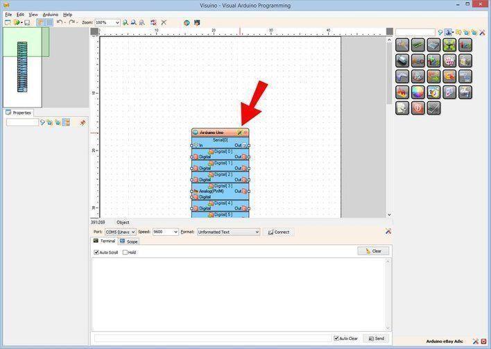
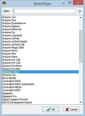
Start Visuino as shown in the first picture Click on the "Tools" button on the Arduino component (Picture 1) in Visuino When the dialog appears, select "Arduino UNO" as shown on Picture 2
In Visuino Add & Set Components


- Add "Clock Generator" component
- Add "MAX6675" component
- Add "TM1637 7 Segment Display 4 Digits Module + 2 Vertical Points (CATALEX)" component
- Select "Display1" and in the properties window set "Points" to True
- Double click on the "Display1" and in the "Digits" window Drag "Analog Display 7 Segments" to the left side
- Close the "Digits" window
In Visuino Connect Components


- Connect "ClockGenerator1" pin [Out] to "Thermometer1" pin [Clock]
- Connect "Thermometer1" pin [Out] to "Display1" pin [In]
- Connect "Thermometer1" pin Control [SPI] to "Arduino" pin SPI [In]
- Connect "Thermometer1" pin Control [Chip Select] to "Arduino" digital pin [10]
- Connect "Display1" pin Control [Clock] to "Arduino" digital pin [8]
- Connect "Display1" pin Control [Data] to "Arduino" digital pin [9]
Generate, Compile, and Upload the Arduino Code

In Visuino, at the bottom click on the "Build" Tab, make sure the correct port is selected, then click on the "Compile/Build and Upload" button.
Play
If you power the Arduino module, The LED Display will show the Temperature from the MAX6675 sensor.
Congratulations! You have completed your project with Visuino. Also attached is the Visuino project, that I created for this tutorial, you can download it and open it in Visuino: https://www.visuino.eu
Downloads
Project Without the TM1637 LED Display


If you do not have the TM1637 LED Display it is not a problem, just connect the "Thermometer1" pin [Out] to Arduino serial pin[In] (see picture).
I also attached a Project file where "Thermometer1" is connected to the Arduino serial pin.