How to Use 123D Make to Create Interlocking Models
by jkmoule in Circuits > Software
4713 Views, 10 Favorites, 0 Comments
How to Use 123D Make to Create Interlocking Models
123D Make is a free software created by Autodesk. It's main purpose is to take a 3D model, and generate a way to make it using 2D contruction techniques. For some examples of what can be made with this program, check out some of my other tutorials:
https://www.instructables.com/id/Laser-Cut-Bear-Fr...
https://www.instructables.com/id/Laser-Cut-Bear/
In this tutorial, I aim to teach you the basics of how to use the software, and establish a level of skill sufficient to make your own models using the program. You can download the program here: http://autodesk-123d-make.en.lo4d.com/download
Download the following file, which is what we will be using in the tutorial. Credit for this design goes to christophecaran from thingiverse, whose design can also be downloaded here: https://www.thingiverse.com/thing:192392
Downloads
Getting Started
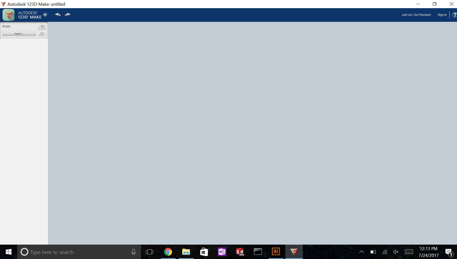
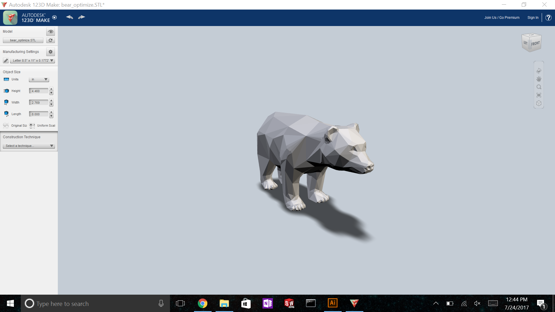
Once you have 123D Make on your computer, open up the program. In the top left corner, you will see a button to 'import' something. Select that to start a project. You will need an stl or obj file, or a similar file type. You can find many 3D models on www.thingiverse.com, or you can make your own using a CAD program. In Autodesk Fusion 360, you can export your part to an .stl file, and in Solidworks you can go to 'save as' and change the file type to .stl. Other CAD programs have similar methods of converting your part file to a 3D object file.
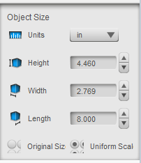
Once you've opened a model, some new options will appear on the left hand menu. You can use manufacturing settings to tell the program what size material you want to make the model out of. Object size is used to scale the object to the desired size. Most importantly is construction technique, which is the main purpose of the program. Select construction technique, and select each of the options and check out what they do. The display of the model will update to reflect which construction technique you have selected. My favorites are interlocked slices and stacked slices.
In this tutorial, we will be learning about the interlocking slices method.
Navigation and Controls
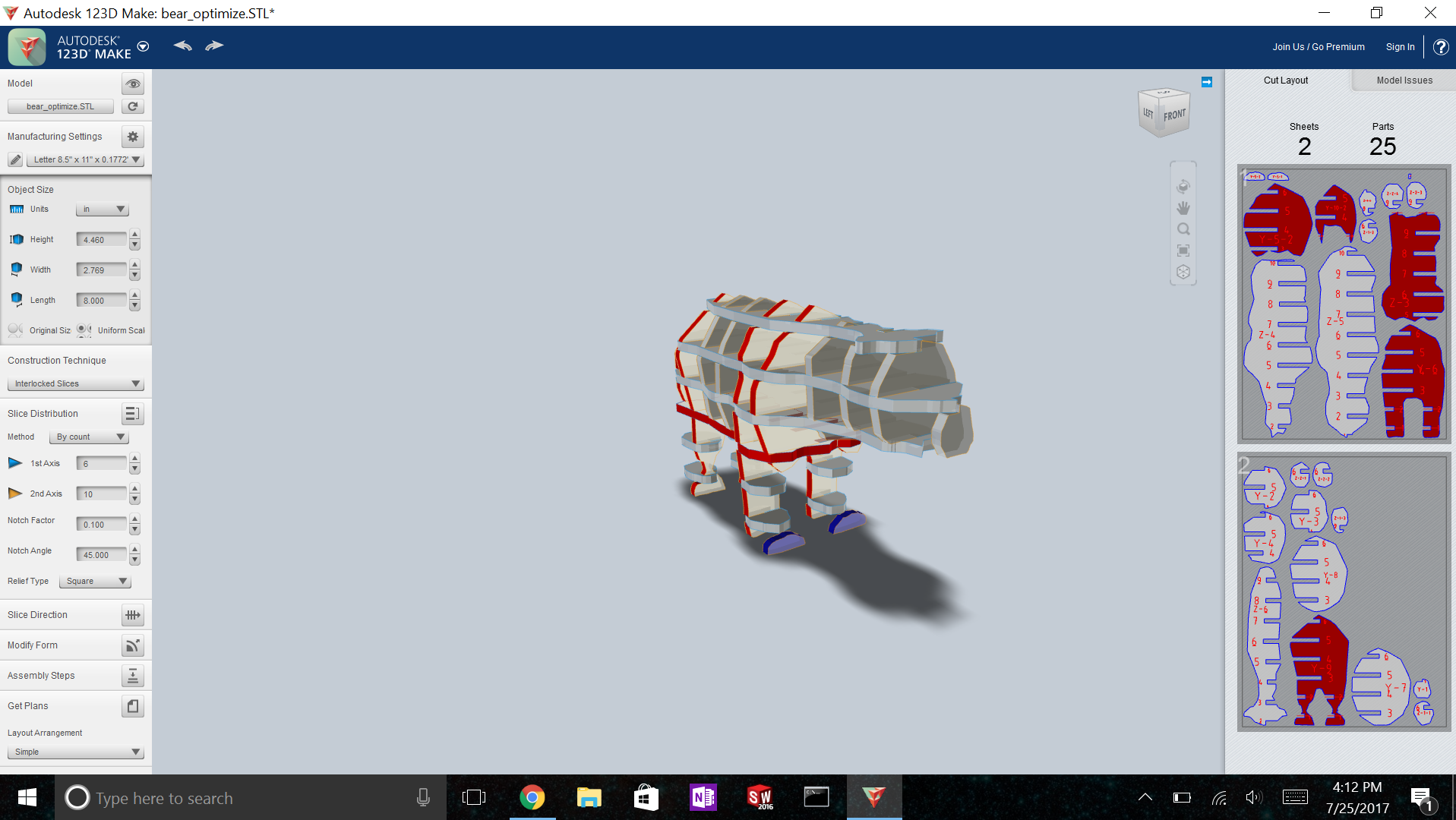
Select interlocked slices as the construction technique. After a construction technique is selected, a significant amount of information is added to the home screen.
To inspect the model, you can use scrolling to zoom in and out, and you can right click and drag to rotate the model. In the top right corner, there is a cube that can be used to navigate views as well. Just under this cube is a small vertical rectangle with 5 commands: the rotate command is selected by default, which allows you to click and drag to rotate. The second item allows you to click and drag to pan.The third command allows you to click and drag to zoom, in case you cannot scroll. The fourth one centers the model on your screen, and the fifth one sets the model view to an isometric view.
If you ever make a mistake, there is no ctrl+z. Instead, use the undo and redo arrows located in the top left hand corner.
Now that the model is broken up in to several parts, it also displays the drawings it will generate on the right hand side. We can ignore that for now, as it will be changing when we edit the model.
On the left hand menu, right under construction technique is an area called slice distribution. We will use this area in the next step to edit the total number of slices and their spacing.
Editting the Slices
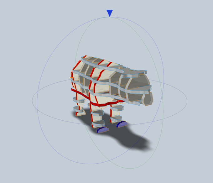
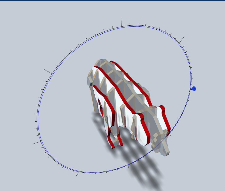
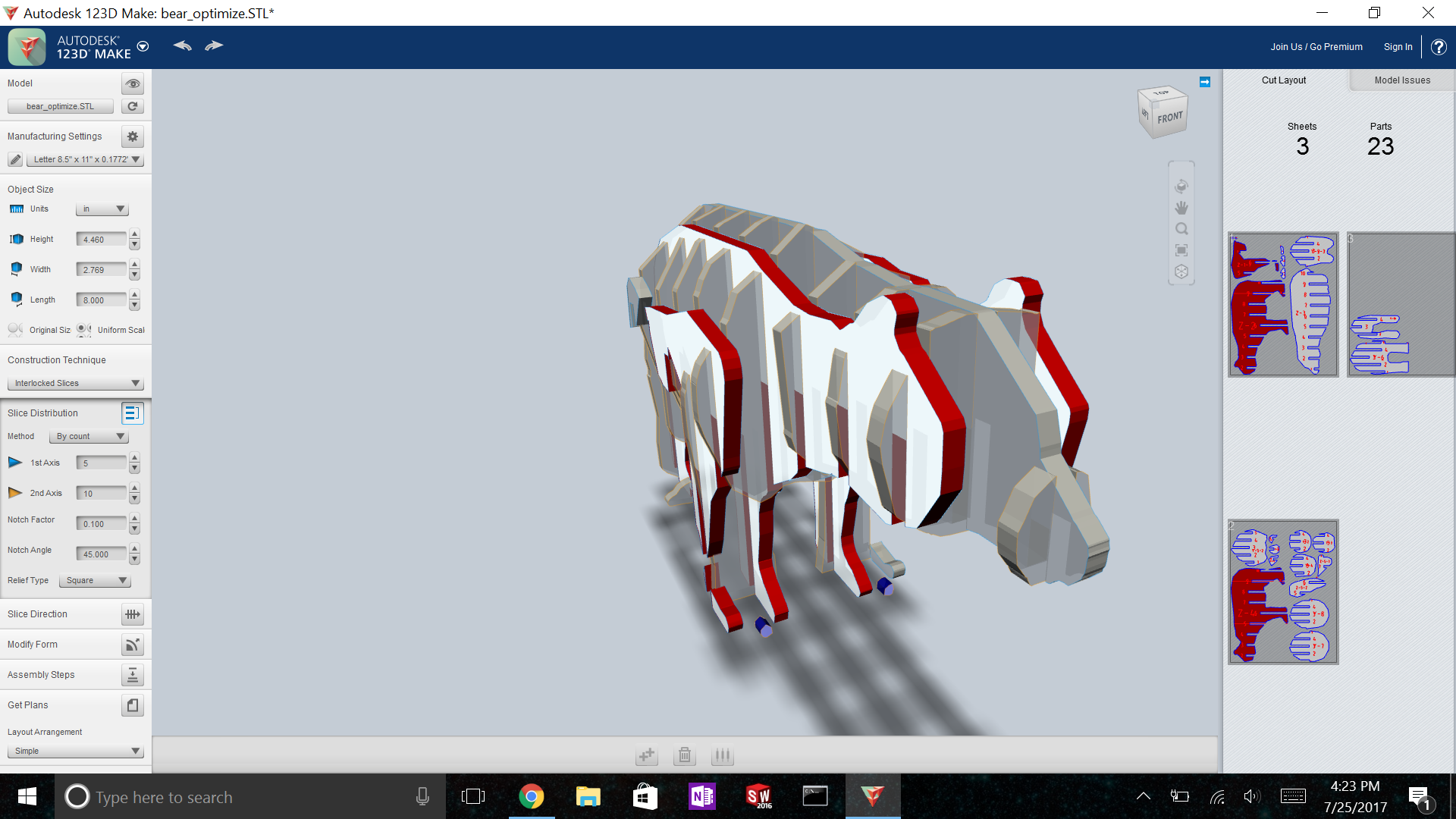
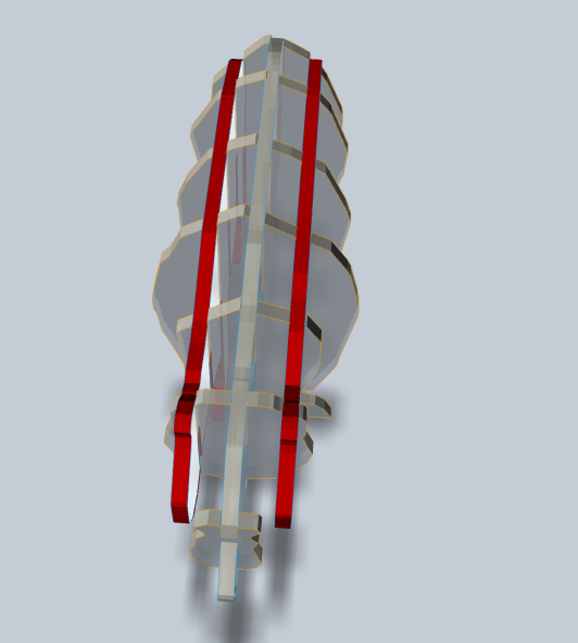
Our model currently has several red pieces and several floating unattached pieces. We will need to remove the floating pieces and make all the pieces not red if we want the model to come out well.
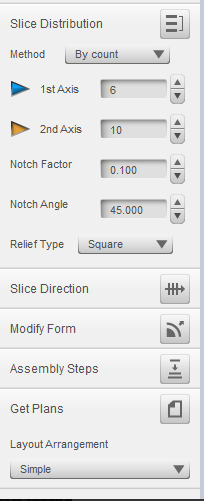
Select 'method' under Slice Distribution, and choose 'by count'. You can also set the number of slices by toggling the spacing, but we want to edit them by count this time. Set the first axis to be 5, and second axis to be 7.
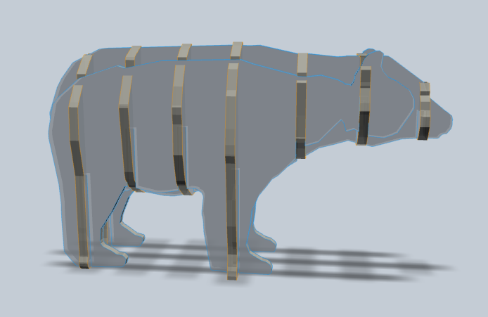
I don't like the way the bear looks with the first axis being horizontal, so I'm going to change it. In the left hand control menu, select 'Slice Direction'. That will generate 3 rings around your model. Click the blue circle that splits the bear between its front and back (shown in the photos). After that ring is selected, click the blue arrow, and drag it to rotate all the slices on that axis. Using this method, we can reorient the first axis slices to be vertical instead of horizontal. This makes the model look more like a bear and easier to assemble.
There are still some red slices though, so we are going to use a tool called 'Modify Form', also located on the left hand side. Using this tool, we can click on an individual slice, and we can move it back and forth or delete it.
Firs off, let's go ahead and delete the two shoulder pieces, or the two edge-most pieces from the first axis, using 'Modify Form'. See the fifth photo for what the bear should look like after doing this. Next, using 'Modify Form' again, we are going to grab the two off-center pieces of the first axis and will drag them outwards a little bit until they are no longer red. Note: this is similar to just setting the total number of slices to 3 instead of 5, but not exactly the same. Go ahead and try setting the number of slices to five to see how the model looks different.
After this step, some of the second axis pieces can become red. To correct this, use the 'Modify Form' tool to drag the second axis pieces forward or backward until they are no longer red. I also dragged the two leg pieces from the second axis to be centered on each leg in the first axis. Take a few minutes to play around with this, and drag the pieces around until you have a model that you are satisfied with that also has no red pieces.
Generating the Laser Cutter File


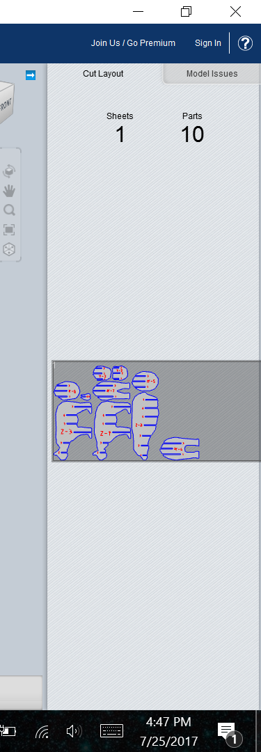
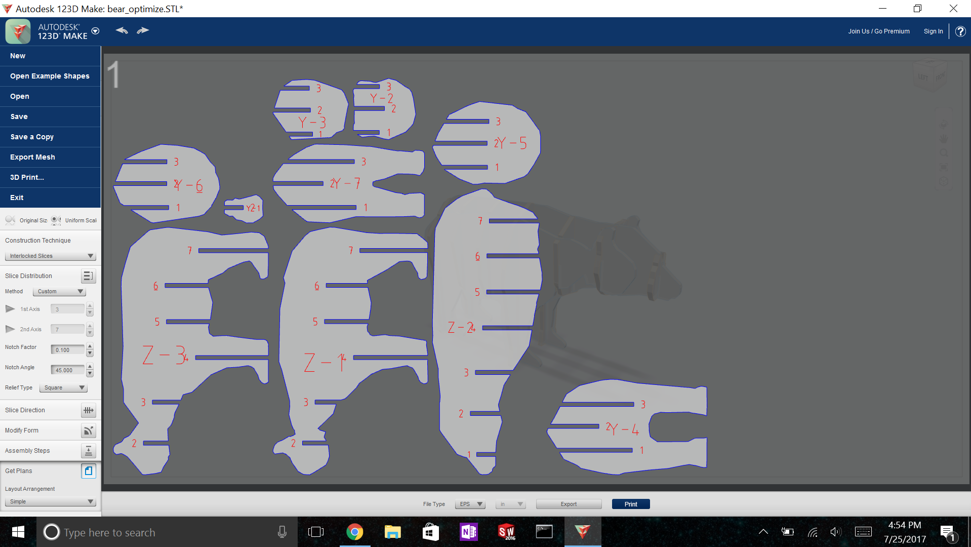
After our model has no errors and we are pleased with how it looks, we will use 123D Make to create a 2D design file that we can export to our laser cutter so we can laser cut the pieces out and make the actual model. First, we need to tell the program what material we are using. Navigate to the manufacturing settings box in the left hand menu.
Select options, and a new tool bar appears on the bottom of the screen. Use this toolbar to input the thickness of the material you will be cutting out of. This is an important step. If you do not put in the correct material thickness, the width of the slots will not be correct and your model will not assemble. You can also put in the length and width of the material you will be using. I will be making the bear out of a 12" x 24" piece of 1/8 inch plywood.
After the manufacturing settings are set, click 'Get Plans' on the bottom left. You will need to be logged in to a free Autodesk account to get your plans, but you can print to a .pdf file with out an account. I usually just print to pdf and open the pdf with illustrator since I typically work offline. The pdf will have all the lines generated as vector entities, so they should be accepted by your laser cutter software. You may just need to change the colors.
If you would like to see how to assemble this bear model, you can go to the Lase Cut Bear instructables on my profile, but its more fun to try assembling your model yourself first.
There you have it, the basics of 123D Make. I hope you enjoyed the tutorial and learned a lot, and if you have any questions feel free to comment and I will reply :)