How to Turn Any Drone Into a Delivery Drone📦 (V1)
by Iloke Alusala in Circuits > Arduino
8293 Views, 46 Favorites, 0 Comments
How to Turn Any Drone Into a Delivery Drone📦 (V1)

Hello Everyone!!!
In this Instructable I am going to show you how I converted my (Commercial) RC drone into a drone capable of delivering parcels that uses a pulley mechanism that is controlled by the transmitter. I was very excited to publish this Instructable because it was a chance to push my limits and venture into a project that I had only dreamt of doing. I hope you find this as exciting as I do!
Why would I want to build a delivery drone from an Arduino?
There has been a lot of hype around the development and usage of delivery drones but where are they? Delivery drones have been the talk of the future because of how efficient and convenient they are. Drones are able to deliver products quickly to virtually any location, they offer a safer delivery system and they offer a higher level of efficiency. At a time like now drones have even become an important tool in fighting the COVID-19 pandemic by helping create more resilient supply chains and serving as the perfect device to deliver items from the recommended six feet away.
There is obviously a lot of work needed to develop an efficient and safe network for a drone delivery system. There are also a lot of disadvantages that come with using drones as a delivery system. Some of these disadvantages are that drones are still relatively expensive and they require a lot of technical familiarity. These disadvantages might be important to consider if we want to build a massive army of delivery drones but for hobbyists like you and I, we just want to have one of our own delivery drones. That's what I'll be teaching you to build today, a delivery drone capable of picking up and dropping off packages while still in the air! Let's dive into the project.
Supplies
This is a list of all the main supplies needed for this project:
- Arduino Nano
- A Drone - I built my own FPV drone. Make sure the Flight Controller supports the PPM protocol and it supports Betaflight.
- Radio Transmitter and Receiver
- A Drone Battery
- DC Motor
- L293d Motor Driver
- PCB Board
- Arduino Uno IDE
- Betaflight Configurator
- An Old Shoelace
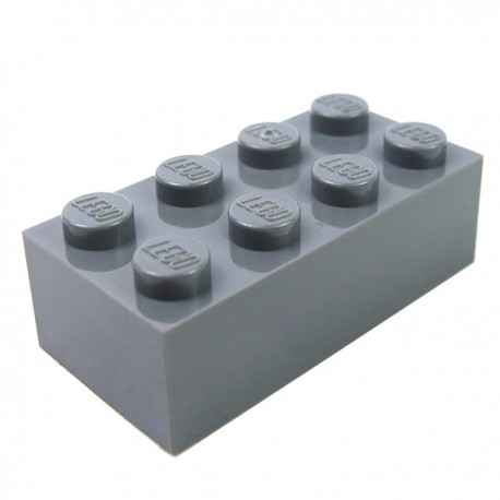
- 2 x 4 Lego Brick
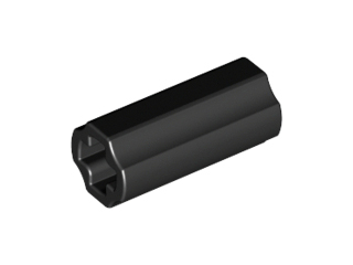
- Lego Technic Axle Connector
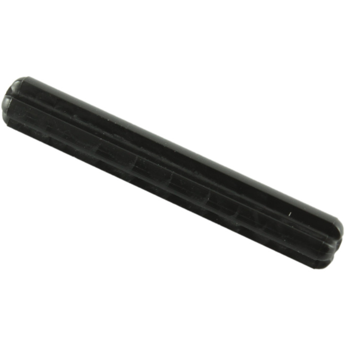
- Lego Technic Axle (size 4)
This is a list of all of the tools needed for the project:
- Soldering Iron
- Soldering Wire
- Wire Strippers
- Electrical Wires (Male - Male and Female - Male)
- Multimeter (One that has a continuity tester on it)
- Precision Screwdriver Set
- Electrical Tape
- Double Sided Tape
The Theory and the Idea

The Theory
This project uses a theory from a previous project I build where I controlled the drone solely from an Arduino Uno without the use of a conventional transmitter or receiver. In place of the transmitter I controlled the drone from my phone using Bluetooth. This is the link to the project.
The theory behind the method in which the Arduino board sends signals to the drone is the same in this project and the current project you are reading, so read "Step 1: The Theory and the Idea" of this project before continuing with the rest of this Instructable. I consider the Bluetooth drone project the predecessor of this project because in the first project we were only sending PPM signals from the Arduino Uno to the drone without interpreting them, now we will interpret the PPM Signals and then send it to the drone.
The Idea
Great! Now that you understand the basics of PPM signals the rest should be quite easy to understand. The idea behind the project is to create a delivery drone that has a pully mechanism that can drop off and pick up packages while the drone is still in the air. The pulley system will be controlled by the same transmitter that is used to fly the drone using different switches and auxiliary channels. So how will we accomplish this?
As we saw in this project we used an Arduino Uno to replace the commercial receiver of the drone and send commands directly from the Arduino Uno. These commands directly translated to the ones my phone sent to the Arduino Uno via Bluetooth.
We now know that it's possible to send commands from the Arduino board to the drone but for this project we need to use both a transmitter and a receiver. It might be easier to refer to the diagram attached to understand the order in which the signal will be sent to the drone, but here is an explanation to help aid in understanding the order:
- The transmitter will send the input from the pilot to the receiver.
- The receiver will then convert the input from the transmitter into a PPM signal which it will send to the Arduino board.
- The Arduino board will read the PPM signal and break it down into the individual channel values.
- The Arduino Board will then convert all of the individual channel values into one PPM signal and send it to the drone.
- Once the drone receives the PPM signal, it will react accordingly.
Now that you understand the idea behind the project. Let's get start with configuring the drone.
Configuring the Drone


The first step is to configure the drone so that it communicates using the PPM protocol. Most drones nowadays are, by default, configured to use the S-bus or I-bus protocols because it is a lot more efficient and reliable that PPM. But in order to allow communication between the Arduino and the drone, the PPM protocol is the best option.
- Connect the Flight Controller of your drone to your computer.
- Open Betaflight and locate the "Configuration tab".
- Scroll down until you find the setting for "Receiver Mode".
- Change the "Receiver mode" to "PPM RX input".
- Click "Save and Reboot" which is at the bottom right of the screen.
Now that your drone has been configured let's head on to the next step. Hopefully you haven't had any challenges so far!
Electronics and Soldering


For this step we will be making all of the electrical connections necessary for the project, so fire up your soldering iron and get your solder ready for some action!
We first need to find which pins are the 5V, Ground and PPM on the Flight Controller. To find them you can use the Pinout Diagram from the manufacturers, it looks something similar to this. There should be one available if you look up your specific Flight Controller on the internet and head over to the official website.
I have attached some Fritzing Images and some additional images to help with the connections.
I recommend that you do everything in a modular manner because it makes soldering the final connections a lot easier.
-
The first step is to connect the L293d motor driver to the PCB. Solder all onto the wires to the L293d motor driver. See image 1.
-
Next connect the Signal pad of the Flight Controller (FC) to pin 2 of the Arduino board, the ground (GND) pad of the FC to that of the Arduino board and the 5V pad of the FC to that on the Arduino board. All 3 of these pins are usually located next to each other on the FC. See image 2. These 5V and GND connections are what will be used to power the Arduino board externally.
-
Connect the 5V and the GND pad of the PCB to the 5V and GND pad on the Arduino board respectively.
-
Next we need to make all of the connections onto the receiver of the drone. There are 3 wires that need to be connected. They are the ground(black), 5V(red) and signal(yellow). Connect the 5V wire onto a 5V pad on the FC, the ground wire onto the GND pin on the FC and the signal wire to pin 3 on the Arduino board.
-
Now that the first part of the soldering is done, let's move on to making all of the necessary connections of the L293d motor driver to the FC and Arduino board.
-
Connect Pin 1 of the motor driver to the 5V pad of the FC.
-
Connect Pin 2 of the motor driver to Pin 6 of the Arduino board.
-
Connect Pin 3 of the motor driver to one of the DC motor's pins.
-
Connect Pin 4 of the motor driver to the GND pad of the FC.
-
Connect Pin 6 of the motor driver to the other pin of the DC motor.
-
Connect Pin 7 of the motor driver to Pin 7 of the Arduino board.
-
Connect Pin 8 of the motor driver to the 5V pad on the FC.
-
And we're done with all the connections, now test that nothing is incorrectly soldered by using the continuity tester on your multimeter. I cannot stress enough about how important using the continuity tester is, it will save you a lot of time and money by helping you avoid short circuiting parts.
Once everything is working fine, head onto the next step.
If the connections are a little messy don't worry you aren't doing anything wrong, there are just a lot of small connections. See image 3.
The Code
Here is the main code for the firmware. Download the files and make sure to save all 5 files in the same directory, on my computer I used the file path: "C:\Users\Administrator\Documents\Arduino\Projects\Delivery_Drone".
Once everything is saved correctly open "Delivery_Drone.ino" in the Arduino IDE. If either "PPMEncoder.cpp", "PPMEncoder.h", "PPMReader.cpp" or "PPMReader.h" are not already added to the file, click "Sketch" --> "Add File..." and add the necessary files. Don't upload it yet, there are some changes that may need to be made to allow the drone to fly smoothly.
The code for PPMEncoder is available here: Code for PPMEncoder
The code for PPMReader is available here: Code for PPMReader
The main code Arduino code is available here: Main Arduino Code
If you got bored reading everything above and decided to skip to the more interesting parts. Remember to alter the code in files "PPMEncoder.cpp" and "PPMEncoder.h" to suit your needs because your drone might not even take off if you don't!
Now onto the assembly of the drone!
Assembly of the Drone


Initially I had used an Arduino Uno for this project, but that shortly turned into a nightmare because there isn't a lot of room in the drone to fit something that large. I ultimately opted for a smaller option which was an Arduino Nano. It was a tight fit but everything worked out fine and I eventually managed to get everything in without short circuiting the drone!
- The first step is to cover all of the exposed pins with some kind of insulator. If you are using a drone like mine where the frame is made of carbon fiber, it could lead to some unnecessary frustration because it is a conducting material so parts could easy short circuit if the wrong wires touch the frame. I used lots of electrical tape to prevent this. See image 4.
- Make sure to lead the motor wires through the drone to the underside of the drone frame. This is where the pulley mechanism will sit so make sure that the wires from the Arduino Board are long enough. See image 5.1.
- The next step is to place the Arduino board and the L293d motor driver in the drone. This might take some maneuvering around but it will fit. See image 5.2.
- The last step is to place the receiver in the frame. I wrapped mine in electrical tape and placed it above the battery connector. See image 6.
Once these 3 parts are placed in the frame of the drone, we can focus on designing the pulley mechanism.
Building the Pulley Mechanism


For the pulley mechanism, I used a few Lego pieces, an old shoelace and the motor.
- First, hollow out a (2 x 4) Lego Brick, you can use a set of pliers for this.
- Next , if you haven't already, solder the motor wires from the Arduino board to the motor and place the motor in the hollow Lego brick.
- Use some electrical tape to hold the motor in the brick and use some more tape to hold the brick to the frame of the drone.
- Now attach the string to the Lego technic axle connector.
- Next connect the Lego Technic Axle Connector to the Lego technic Axle. Connect this to the motor shaft.
- The final step is to connect the string to the pulley mechanism. For this I used an old shoelace and just stuck it onto the Axle connector.
This is design managed to hold a maximum of 1KG of weight, imagine what you could deliver with that!
Controlling the Drone and the Pulley

In this step I will be covering how to control the drone and the pulley mechanism.
As I mentioned earlier in the Instructable, the main advancement with this drone is its ability to drop off and pick up packages while still in the air so how do we control this while the drone is still flying.
The image at the top shows the type of transmitter that I use to control the drone. As I have pointed out in the image, I use the 3-position toggle switch to control the state of the pulley motor. These are the possible states of the pulley based on which position the toggle switch is in:
- Position-1: The pulley motor is turned off
- Position-2: The pulley motor rotates clockwise, lowering the package
- Position-3: The pulley motor rotates anticlockwise, lifting the package up
Since the controls of the pulley motor are dependent on the state of the toggle switch, you are able to continue flying the drone while switching between the different pulley motor states.
As for controlling the drone, the controls remain the same. The only addition is that of the functionality on the 3-position toggle switch.
Flight Testing

The drone flew quite well during its test flights and almost delivered the package directly on the "X" mark. The only thing to watch out for is that the longer the string of the package is, the harder it is to pilot the drone. Reel the string in before flying the package because it makes flying the drone a lot easier.
In the video above, I show how the drone delivers the packages. I didn't tie the rope to the pulley so that the package would drop as lowered it. I would consider this test flight a success.
Overall Impressions
The drone flew as well as I thought it would fly but there are still a lot of things that could have been improved such as the pulley mechanism.
As someone who enjoys tinkering with electronics and building things, this project was one where I had a lot of fun. There was not a lot of research done on reading and generating PPM signals with an Arduino board, so I'm proud of the fact that I actually got the Arduino to communicate with the FC on the drone. I feel like this is what making an instructable is about, pushing your limits and sharing the results with others who share the same interests. I hope that those of you who enjoy electronics and circuits as well as those who are new to the field have a go at this project and learn something new from it.
I hope that you enjoyed this instructable and you attempt the project.
You won't regret it!!!
Written by Iloke Alusala