Basic Projects | How to Start on Raspberry Pi Home Automation | ESPHome
by mcmchris in Circuits > Raspberry Pi
3168 Views, 8 Favorites, 0 Comments
Basic Projects | How to Start on Raspberry Pi Home Automation | ESPHome
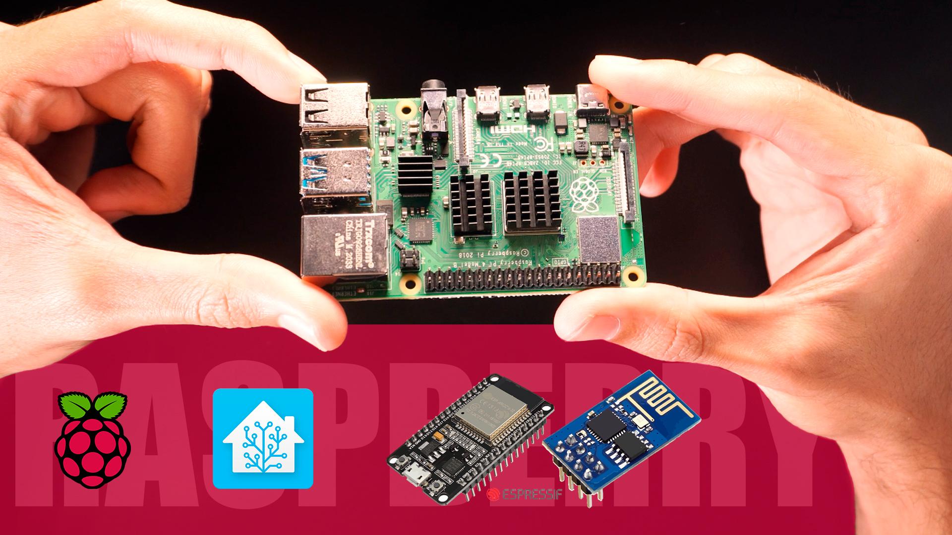
Hello everyone, here Chris, and I want to show you a simple guide to begin your journey in Raspberry Pi home automation projects with ESPhome, this is an Add on of Home Assistant (Raspberry OS) that let us turn ESP boards on nodes capable of handle sensors and actuators.
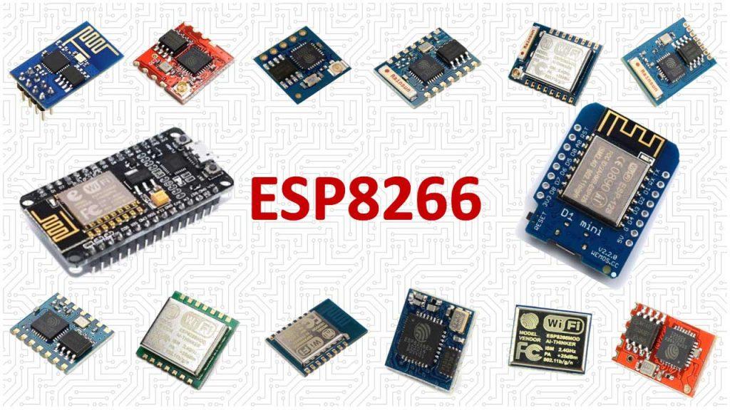
If you have worked with the ESP8266, ESP32, ESP-01 boards to make any IoT project, now you will be able to configure your Raspberry Pi as the server of your projects, that let you stop using paid services like Blynk, Adafruit.IO, or any other.
You can reflash the firmware of any node with OTA without the need of connect them by USB to the Raspberry.
Here I leave you a tutorial with all the information so you can make your own version.If you are a visual learner I know that a video worth more than 1000 words, so here is a Tutorial video. (I am a Spanish speaker, so please consider turning on English subtitles):
Skills Required
This project may seem difficult or very complex for beginners, but it is definitely not completely, since you will have all the guidance for the construction, it was difficult for me to design it to make life a little easier for you. Any conceptual doubt, you are free to ask it without problems.
You should have an understanding of:
-Experience with ESP Boards (Optional).
-Arduino Programming.
Components and Parts List
.png)
.png)
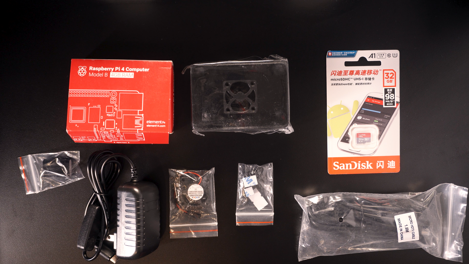
- Here is the list of what you will need for the whole process:
- Raspberry Pi Starter Kit.
- DHT11 Temperature and humidity sensor.
- LED (any color works)
- 220 ohm resistor
- Jumper wires
- Breadboard
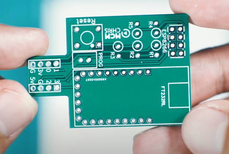
- ESP-01 DIY Programmer Shield
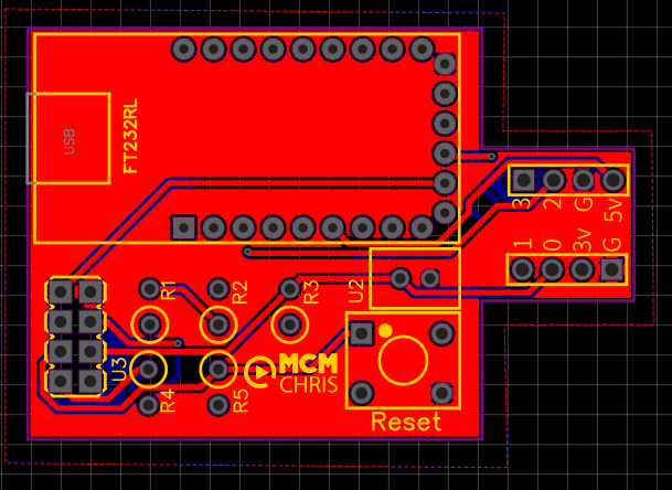
PCB Design and Ordering
.png)

For the implementation of a good project we need a reliable assembly for the circuit that makes it up, and there is no better way to do it than with a good PCB.
Here you can download EasyEDA PCB design to order your custom PCB of the programming shield.
I suggest JLCPCB:
$2 for 1-4 Layer PCBs⚡, Get SMT Coupons🎫
UnZip the .rar file with a software like WinRar or any other.
Downloads
Raspberry Pi Unboxing and Housing Setup
.png)
.png)
.png)
.png)
.png)
.png)
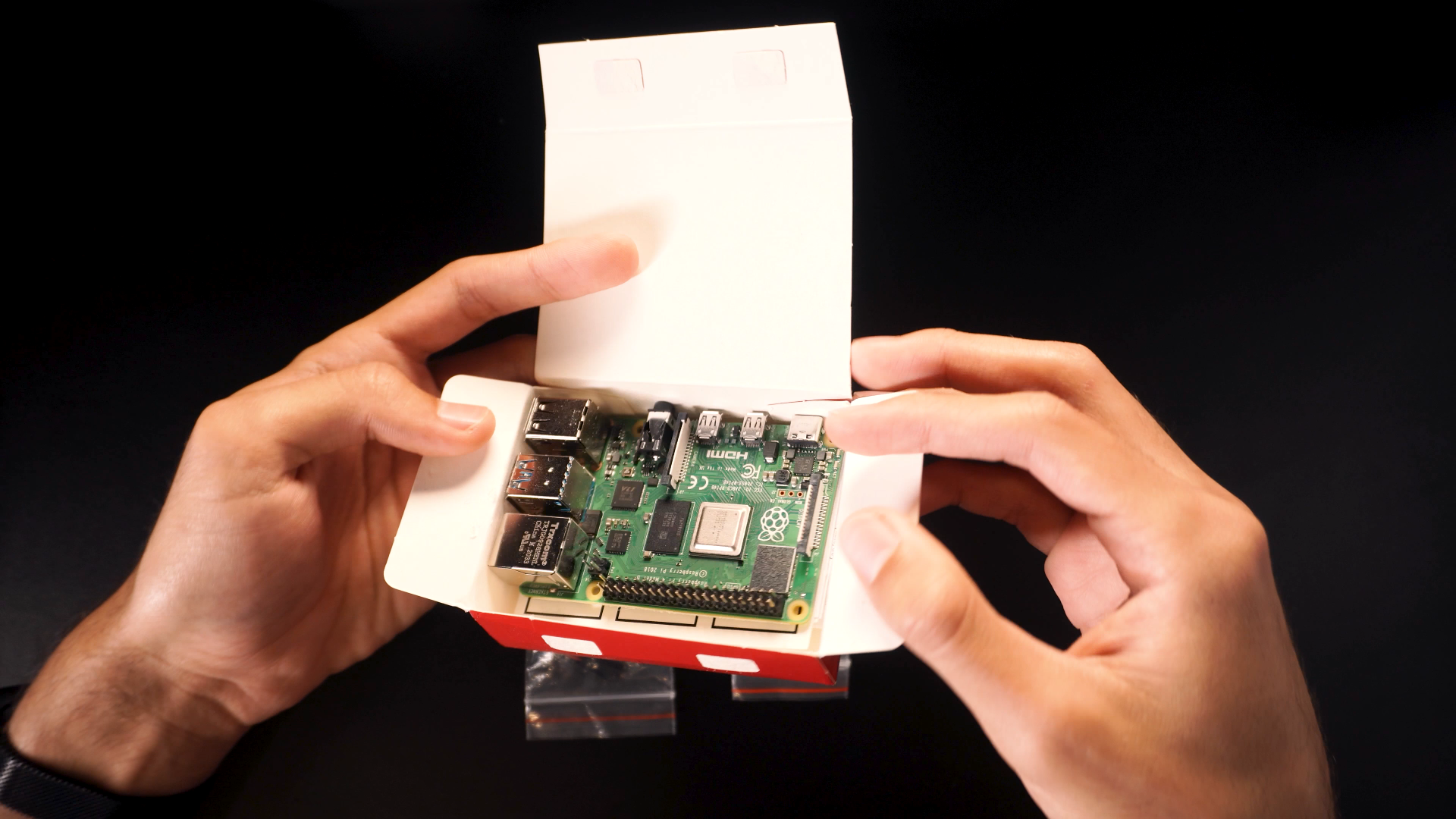
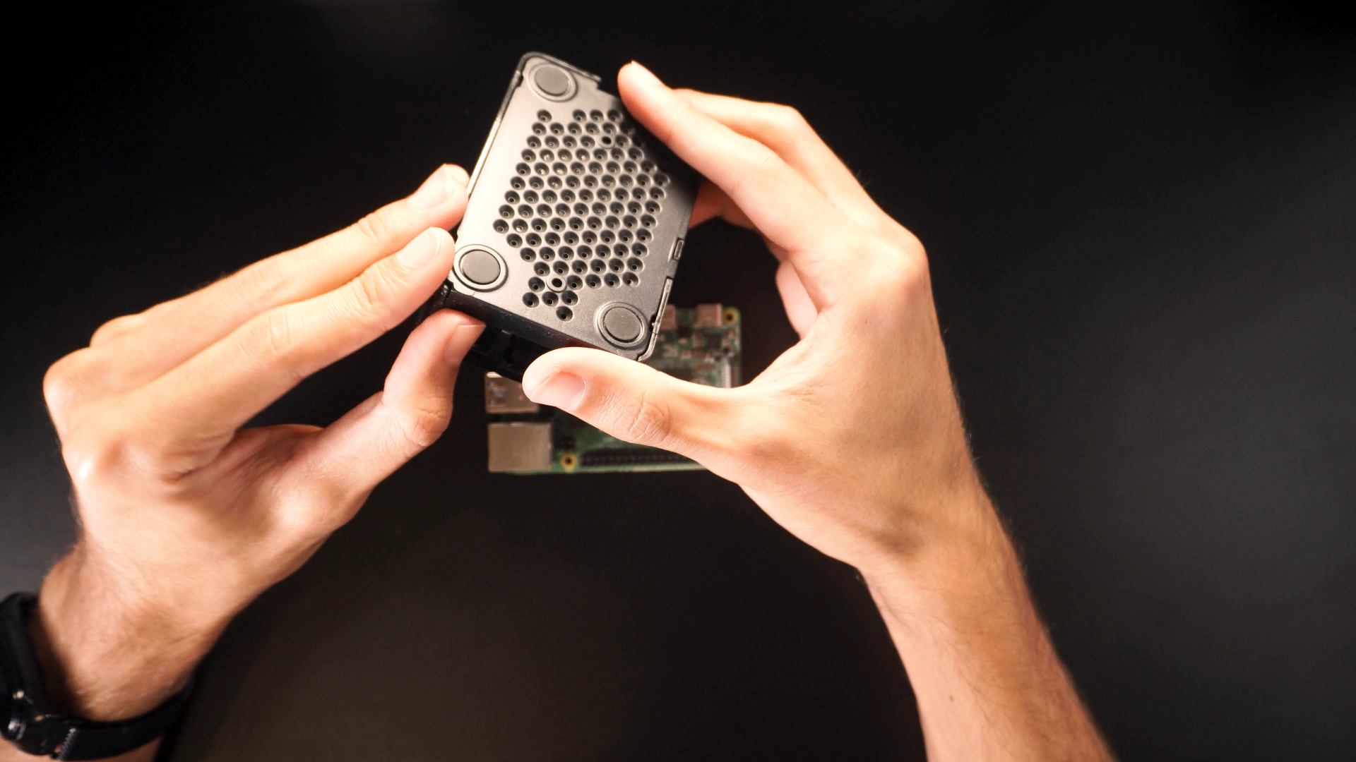
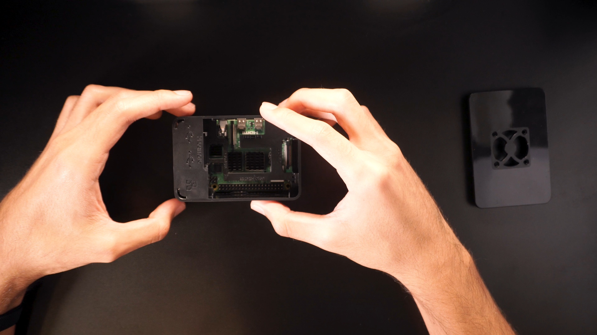
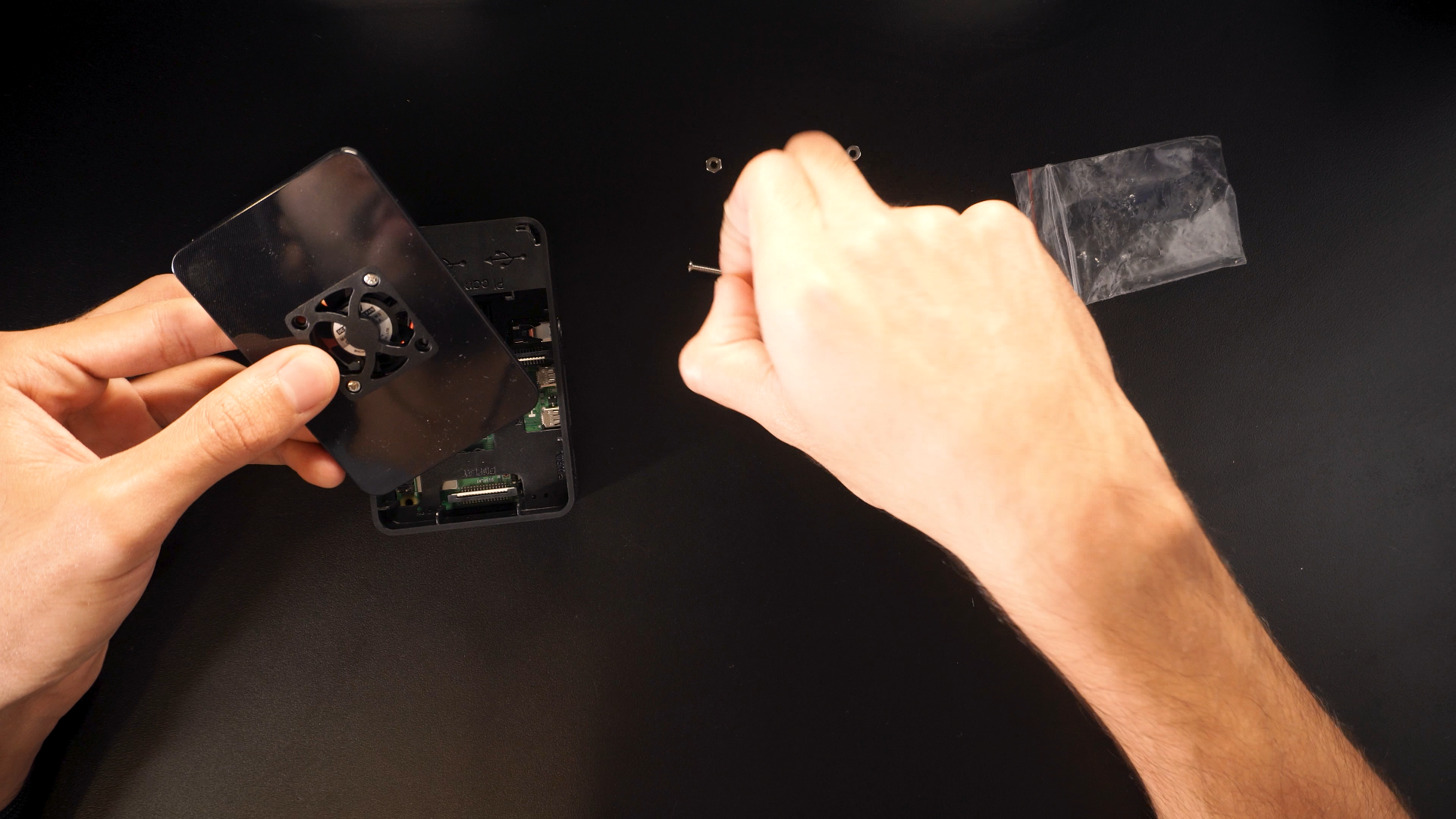
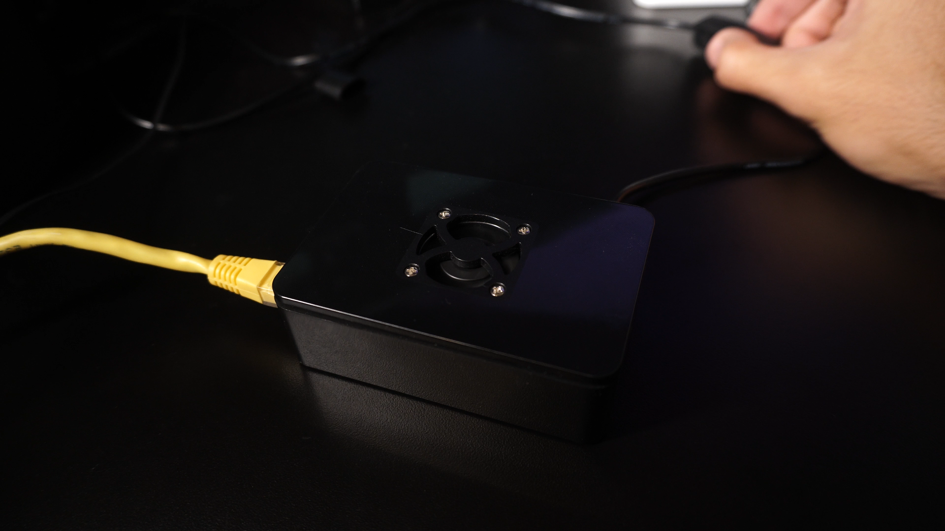
The Raspberry Pi Board need some extras to work properly (for a long term use).
- Unbox the board, verify everything is right.
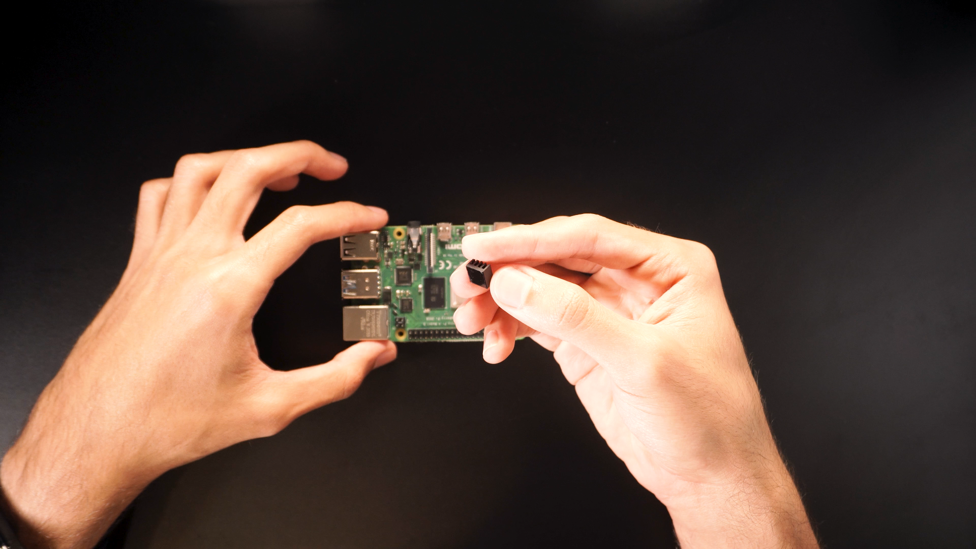
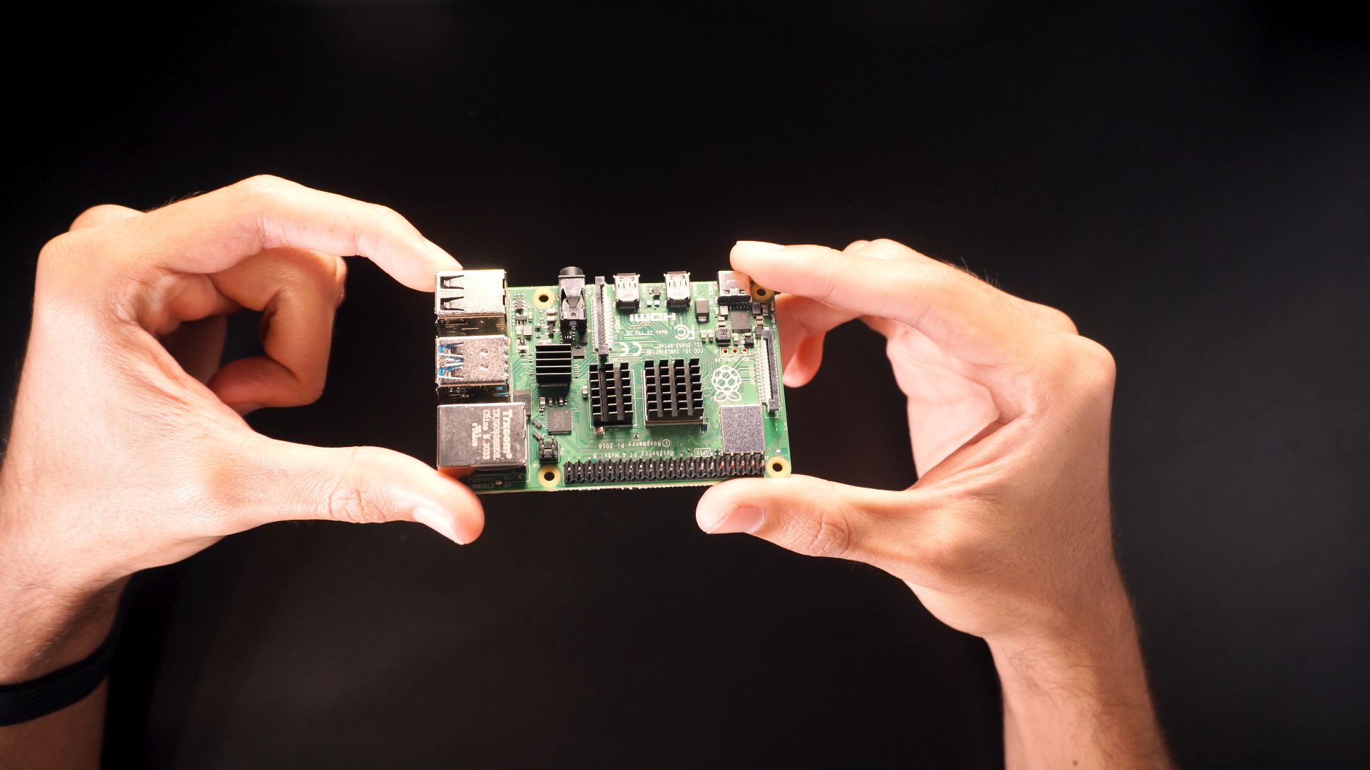
- Place the heatsinks on top of the ICs respectively.
- Place the Raspberry Pi inside it protective case.
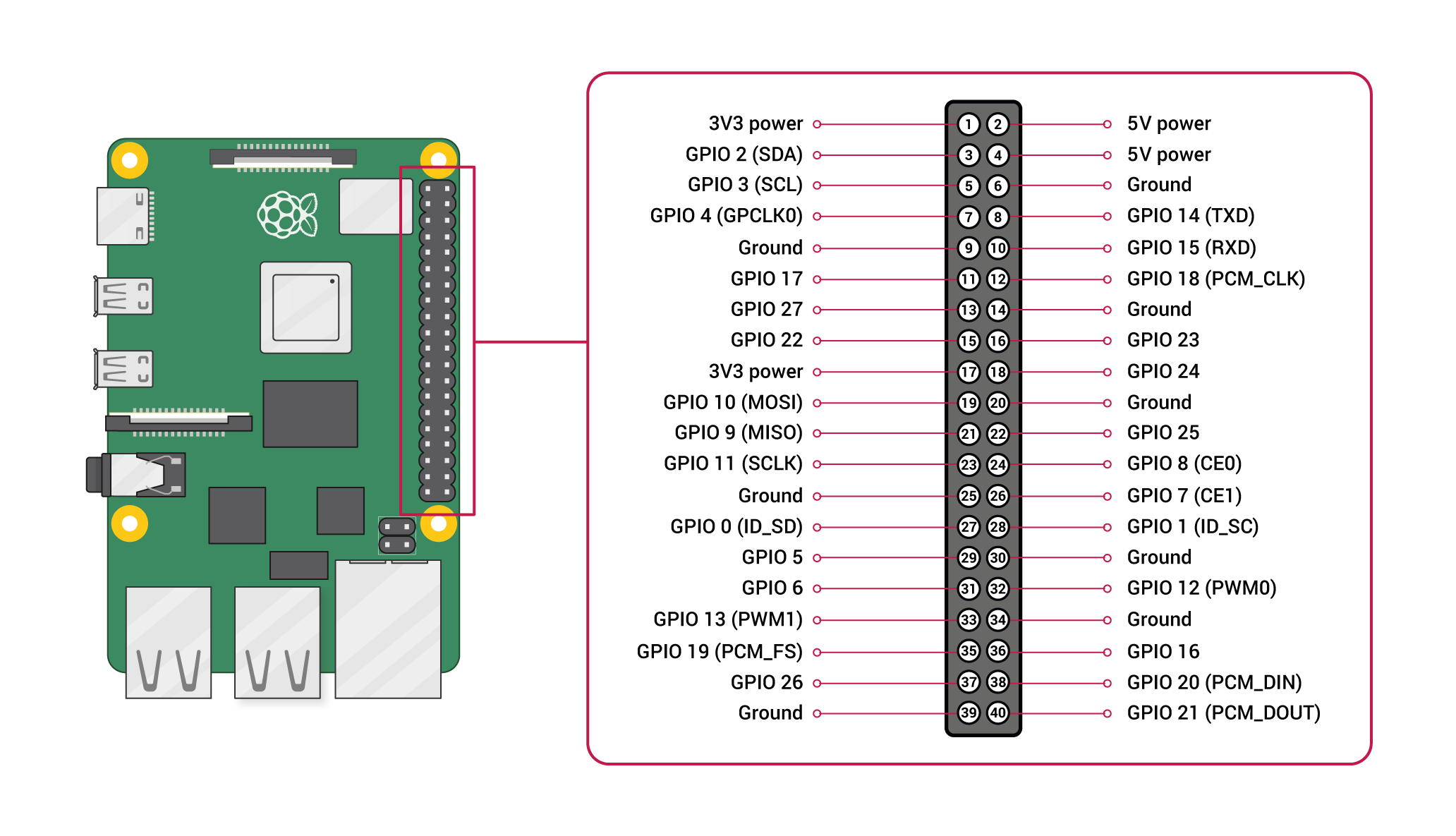
- Connect the fan to the 5v-Gnd pins of the board.
Flashing the Raspberry MicroSD Card
.png)
.png)
.png)
.png)
.png)
.png)
.png)
.png)
.png)
.png)
.png)
.png)
.png)
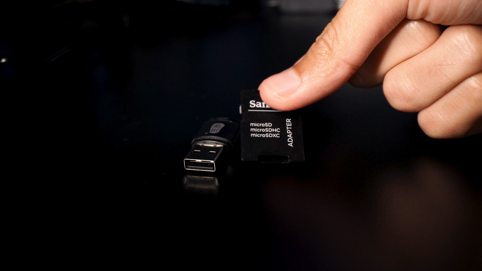
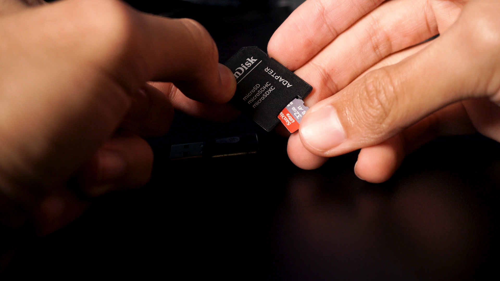
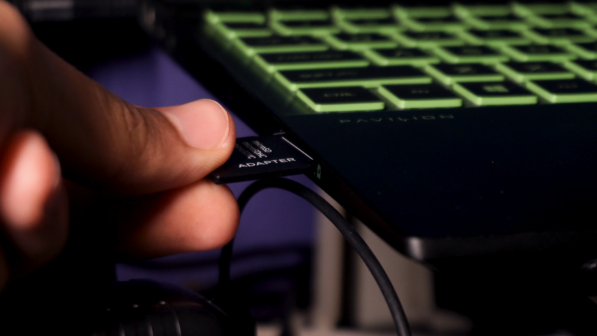
- Select the MicroSD adapter that fix your computer.
- Insert it to an SD slot or USB port.
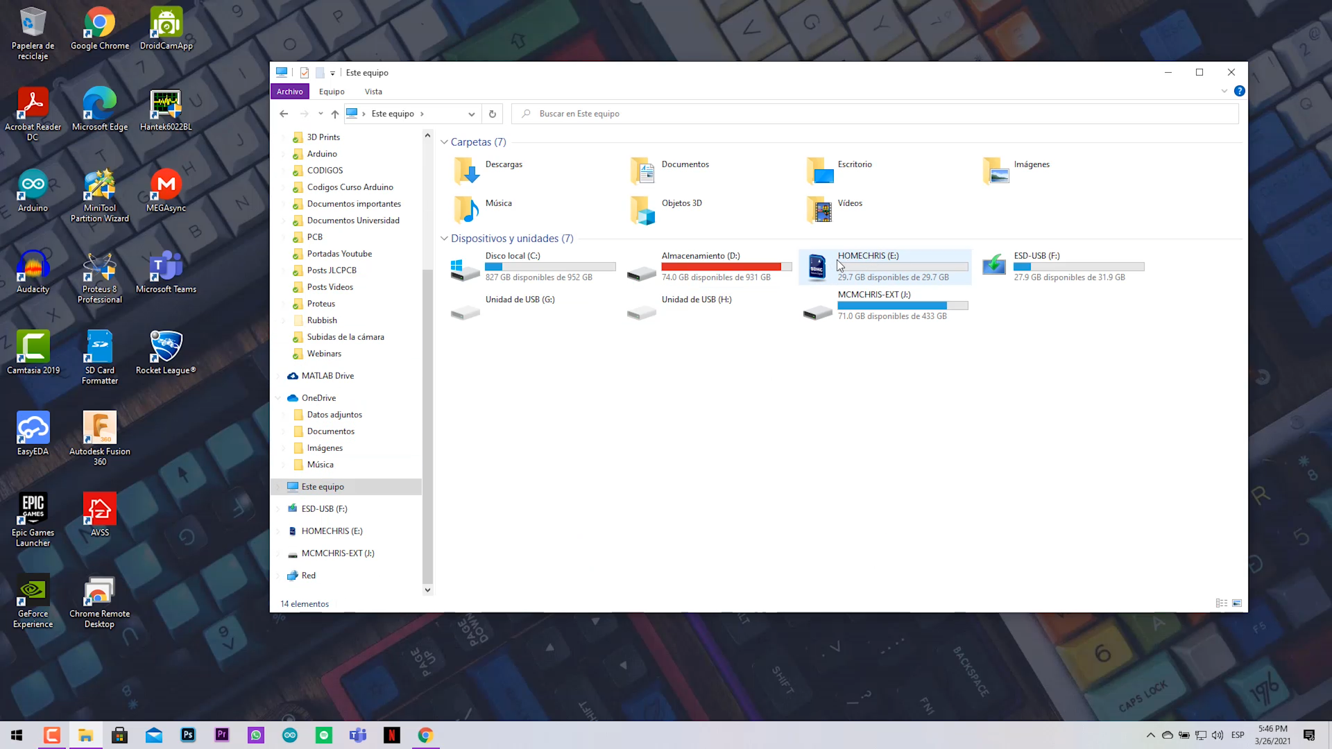
- Verify your PC recognize the storage. (Format it)
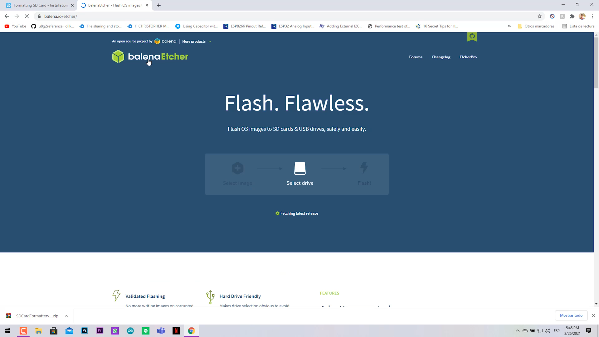
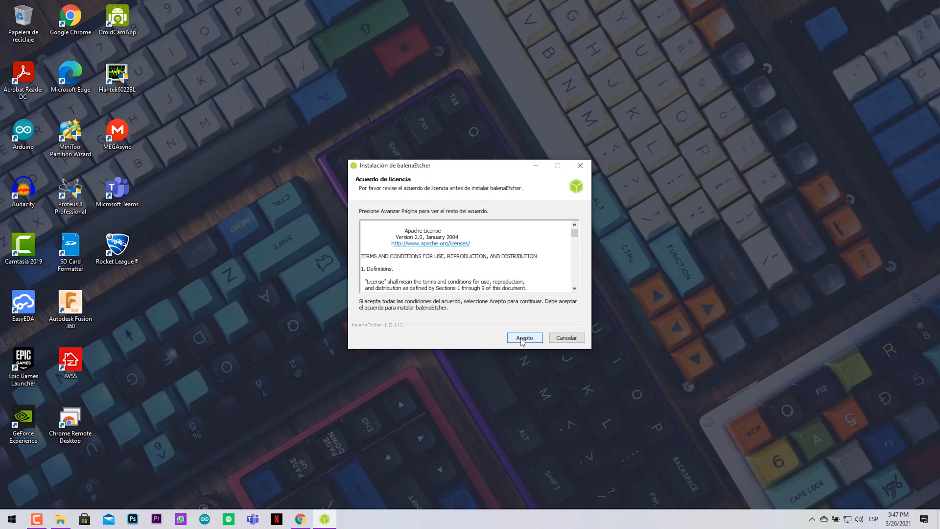
- Install the flasher software. (balenaEtcher) and run it.
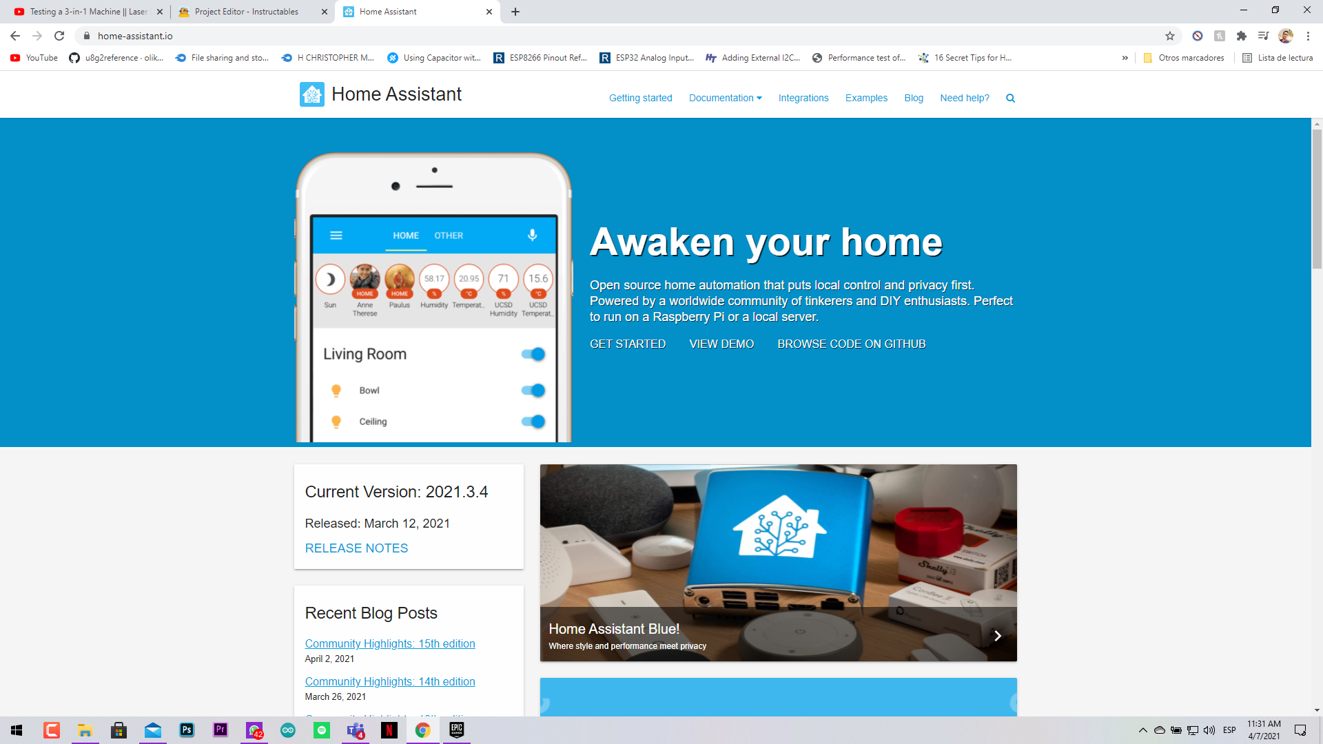
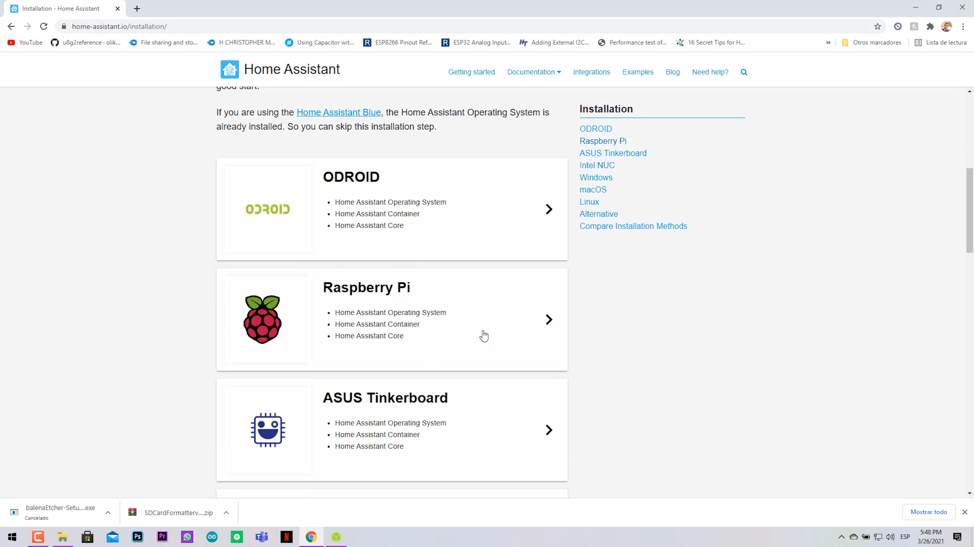
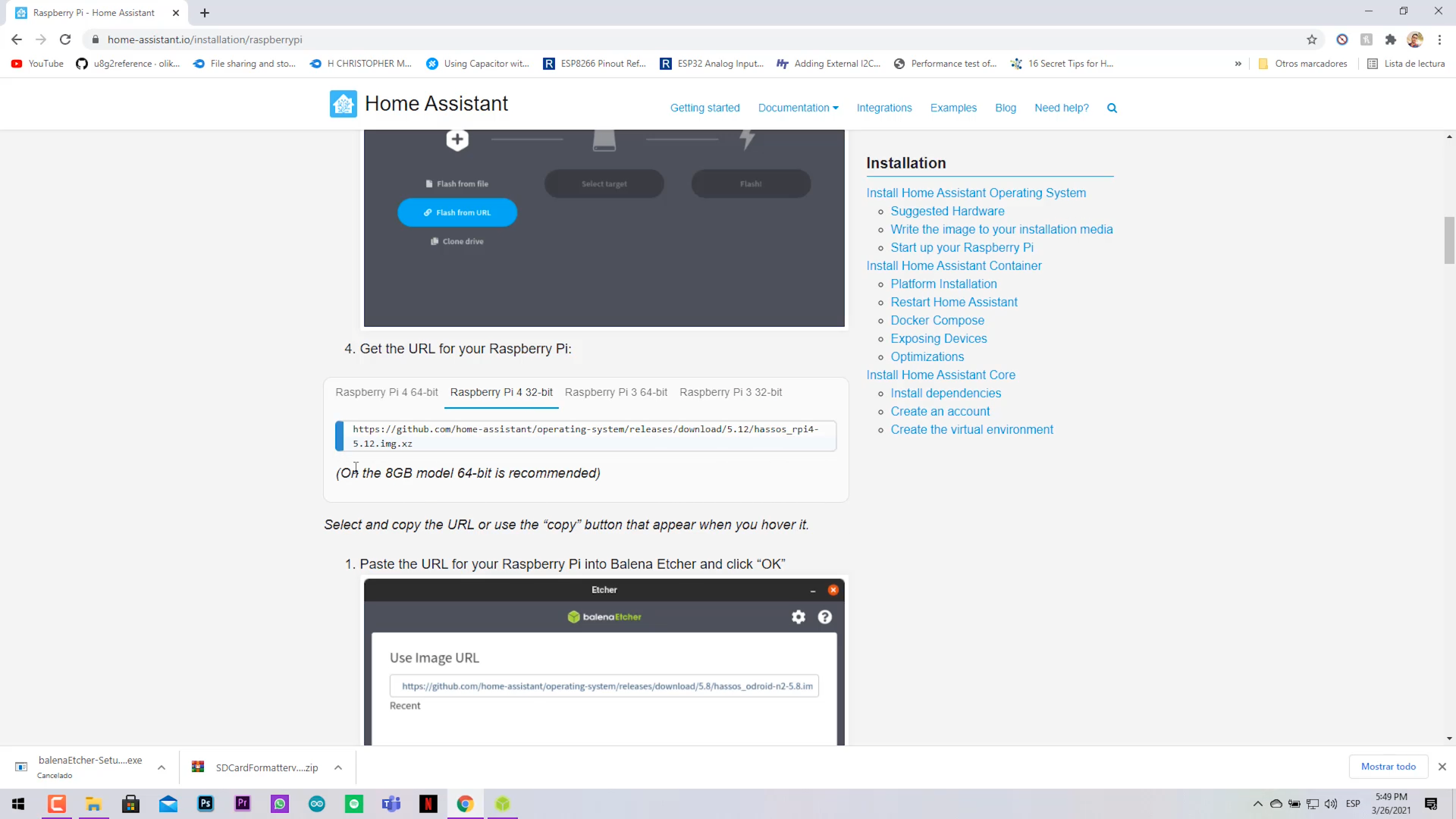
- Go to Home Assistant website (Getting Starter>Installation>Raspberry Pi) and select the right image for your board.
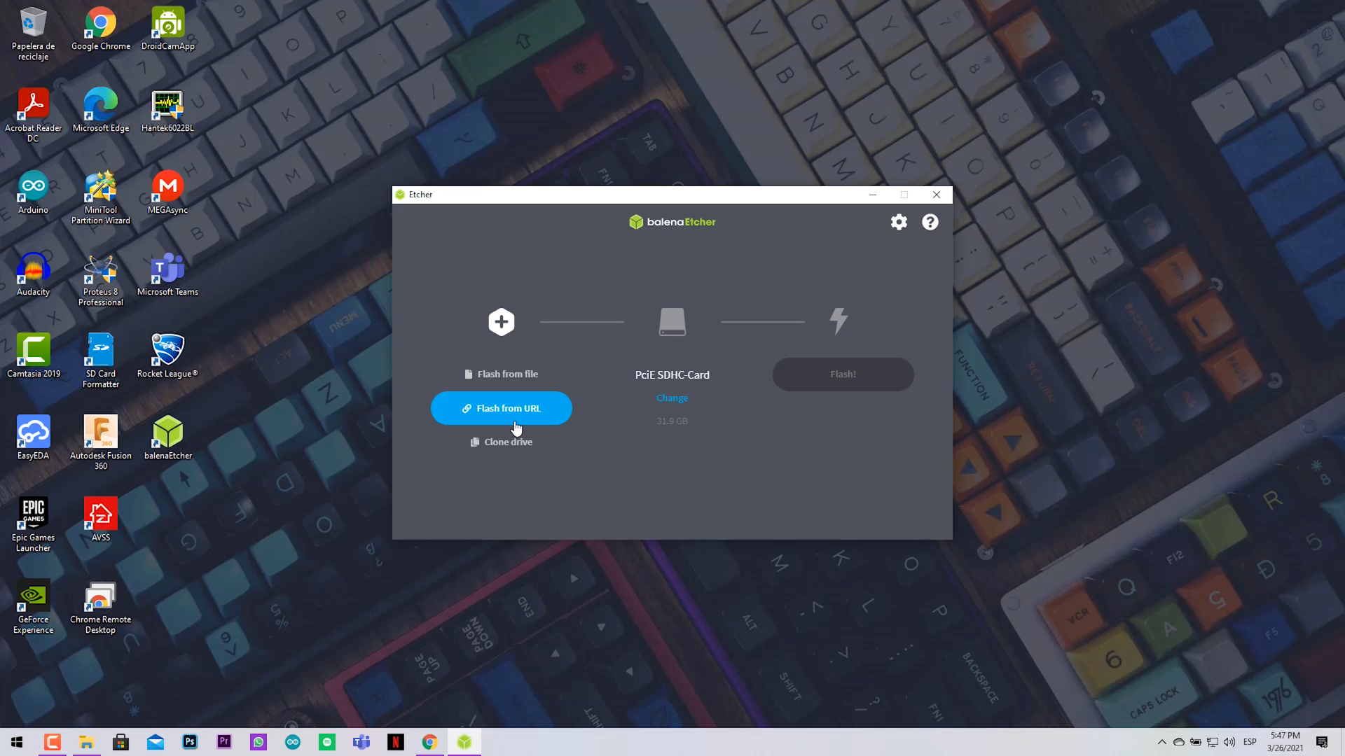
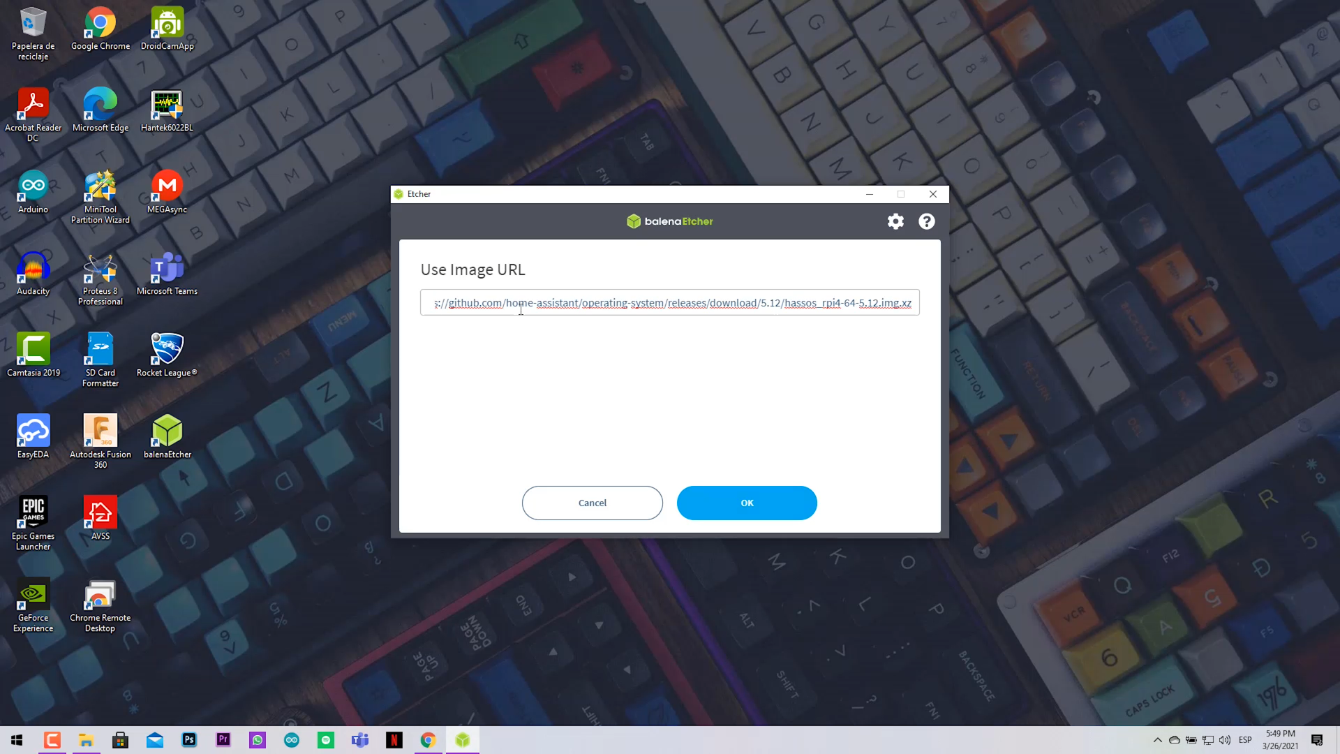
- Select the Flash from URL option and paste the copied URL.
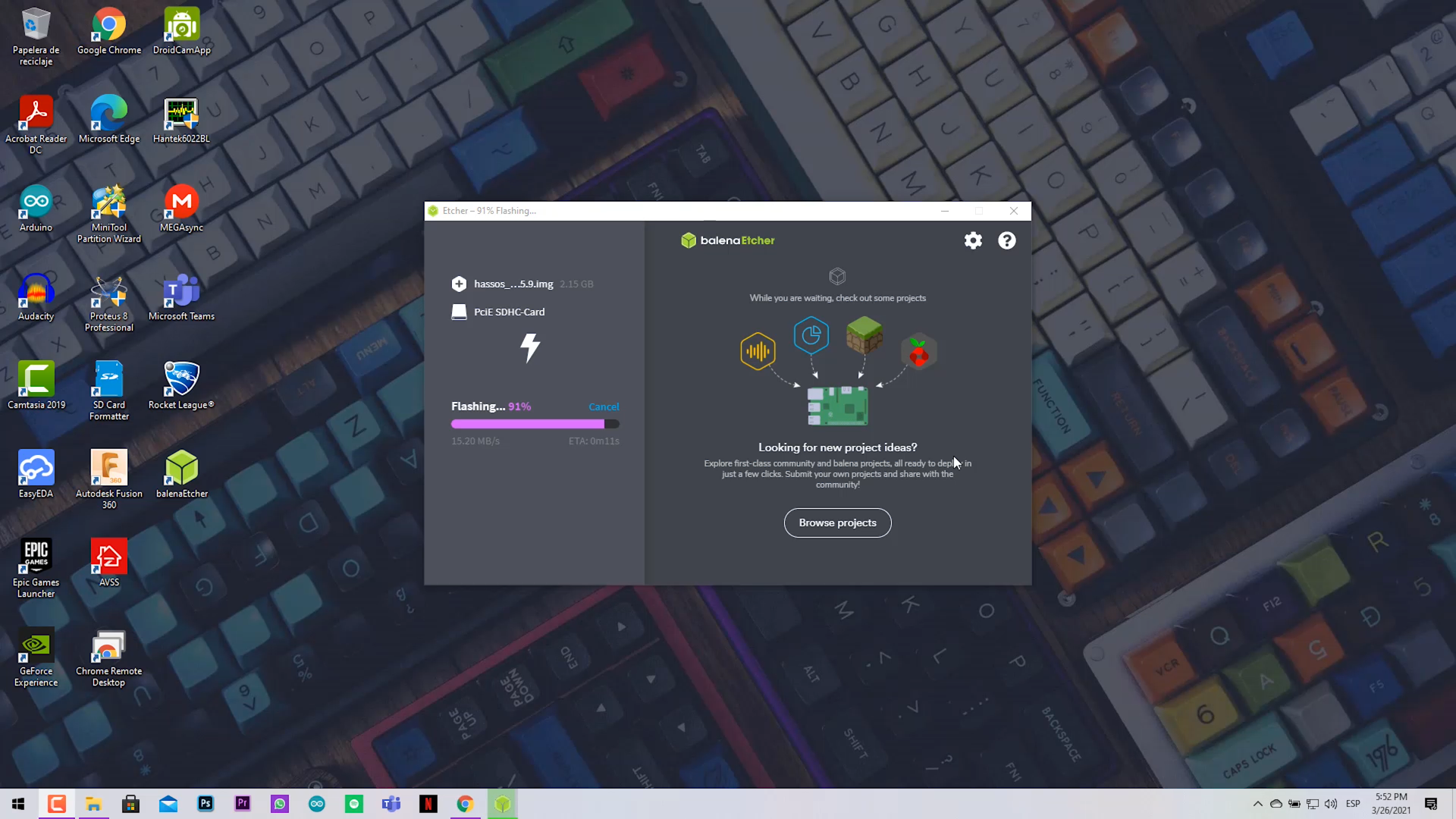
- Verify you choose the right storage destiny (The MicroSD Card).
- Click on Flash and wait for it.
Setting Up the Raspberry Pi and Turning On
.png)
.png)
.png)
.png)
.png)
.png)
.png)
.png)
.png)
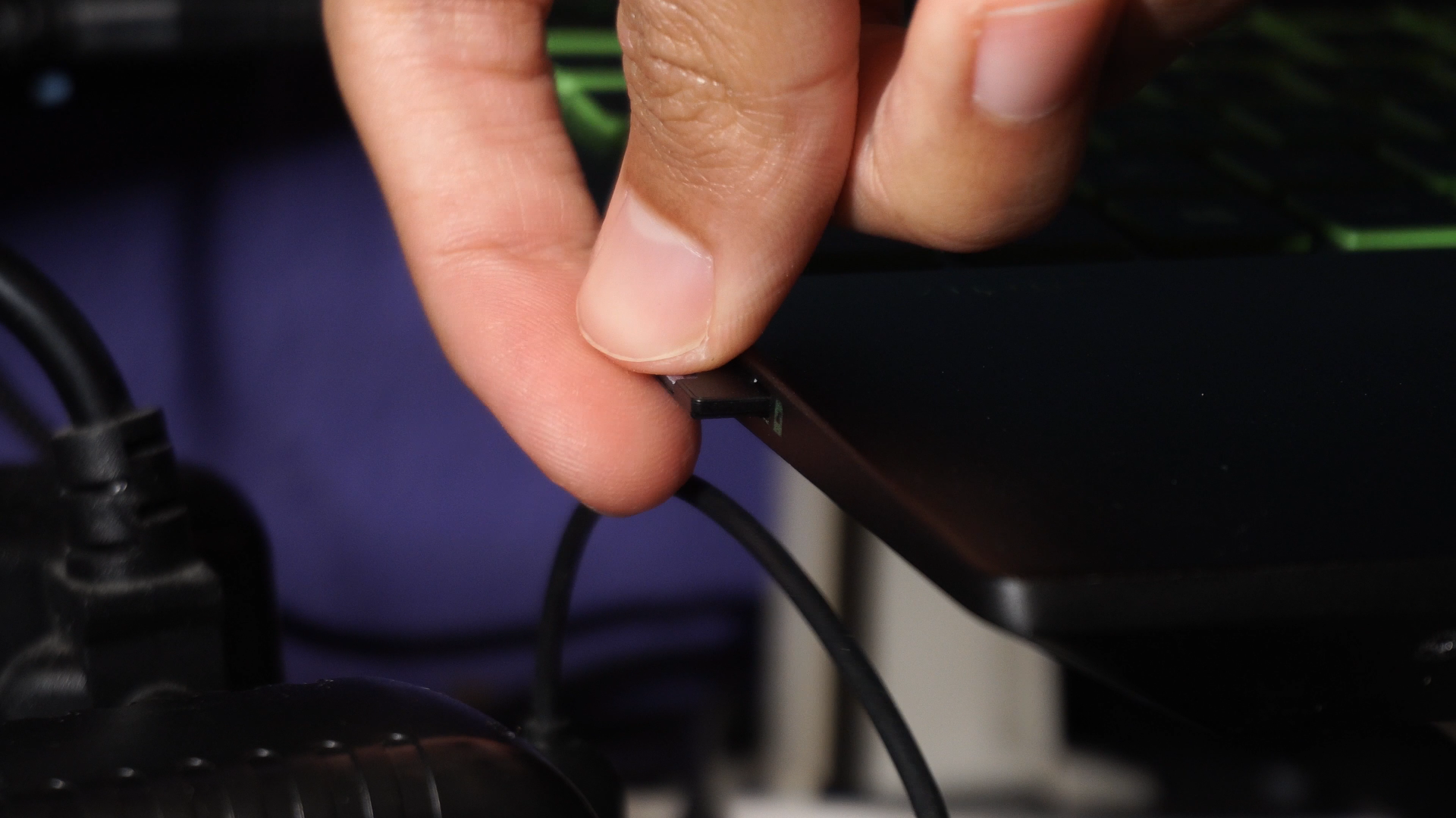
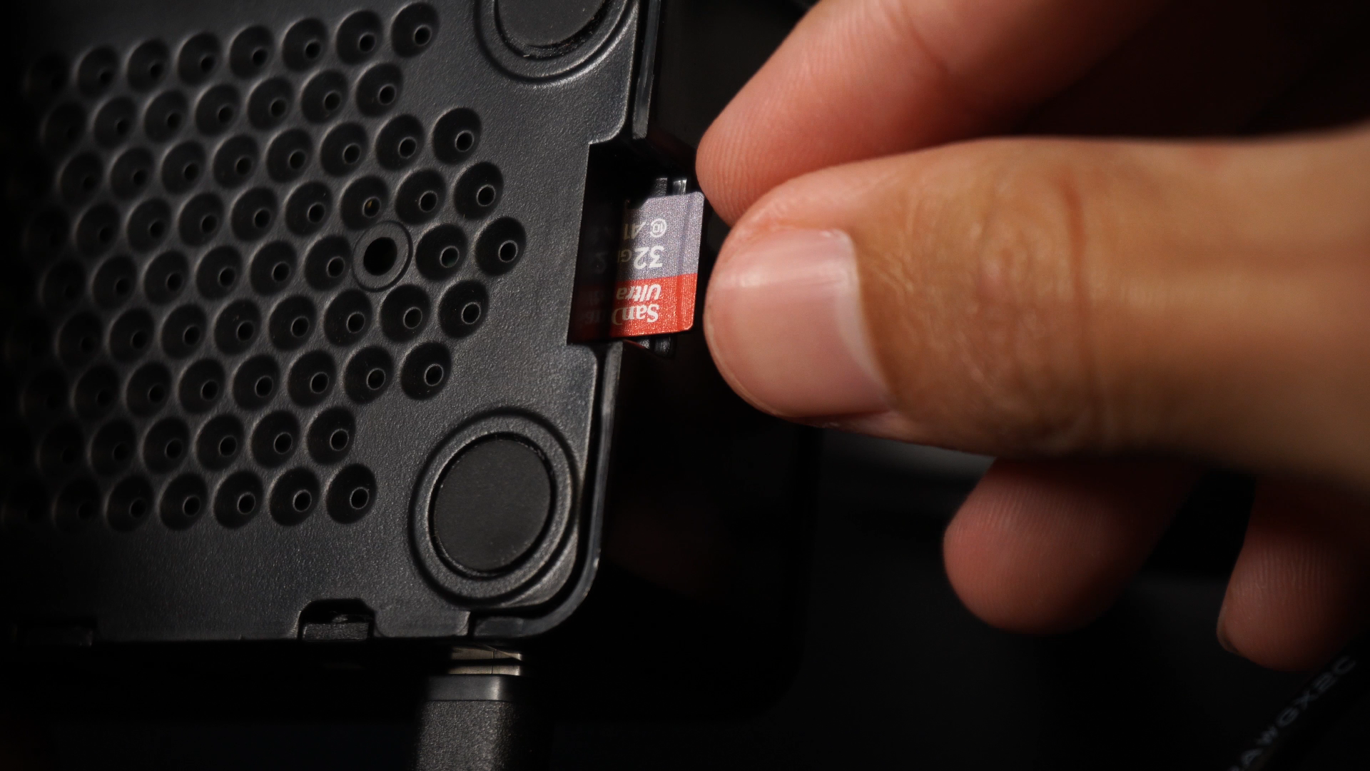
- Extract the microSD from your computer.
- Insert it in the MicroSD slot in the Raspberry Pi.
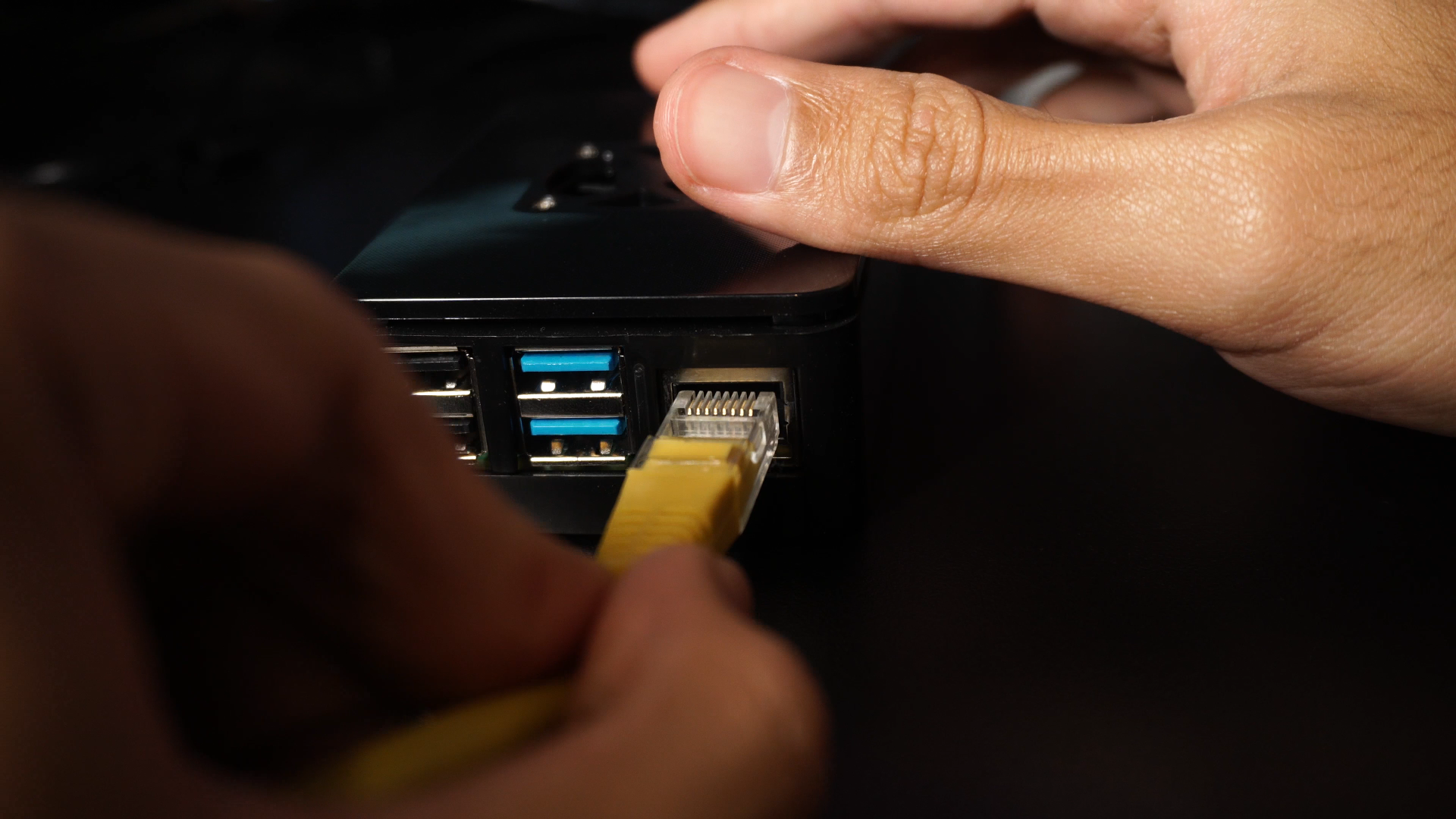
- Connect the Ethernet cable from your router or modem to your Rasp.
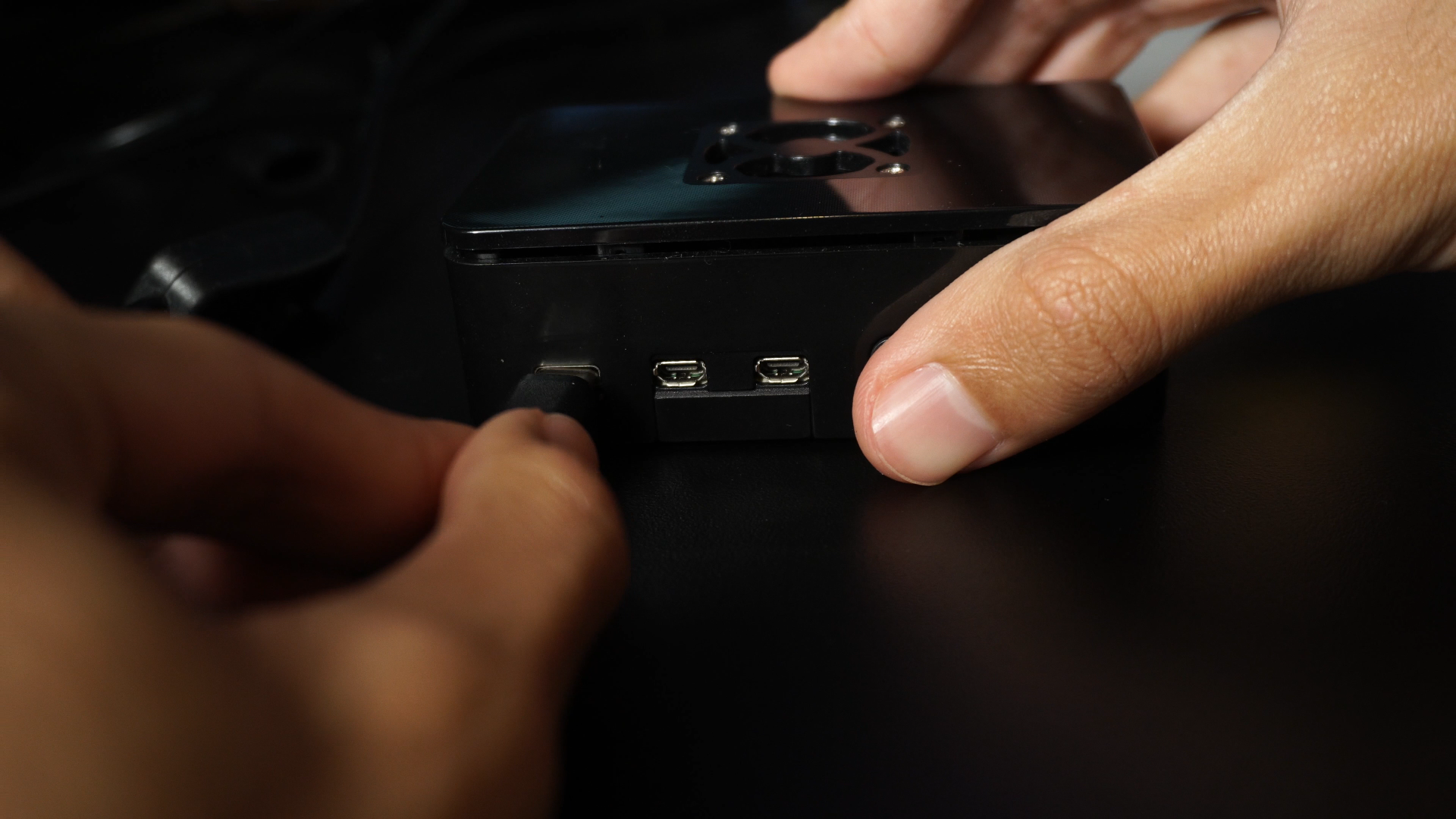
- Connect the power cable.
- Turn on the board.
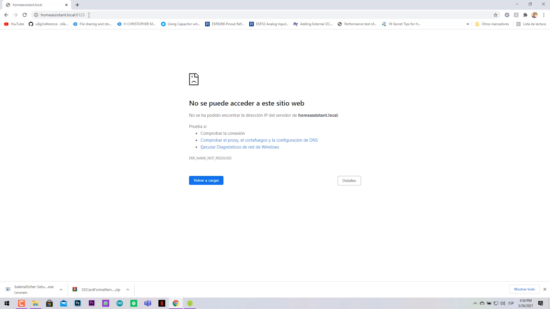
Now you must go to your favorite Web browser and type : http://homeassistant.local:8123
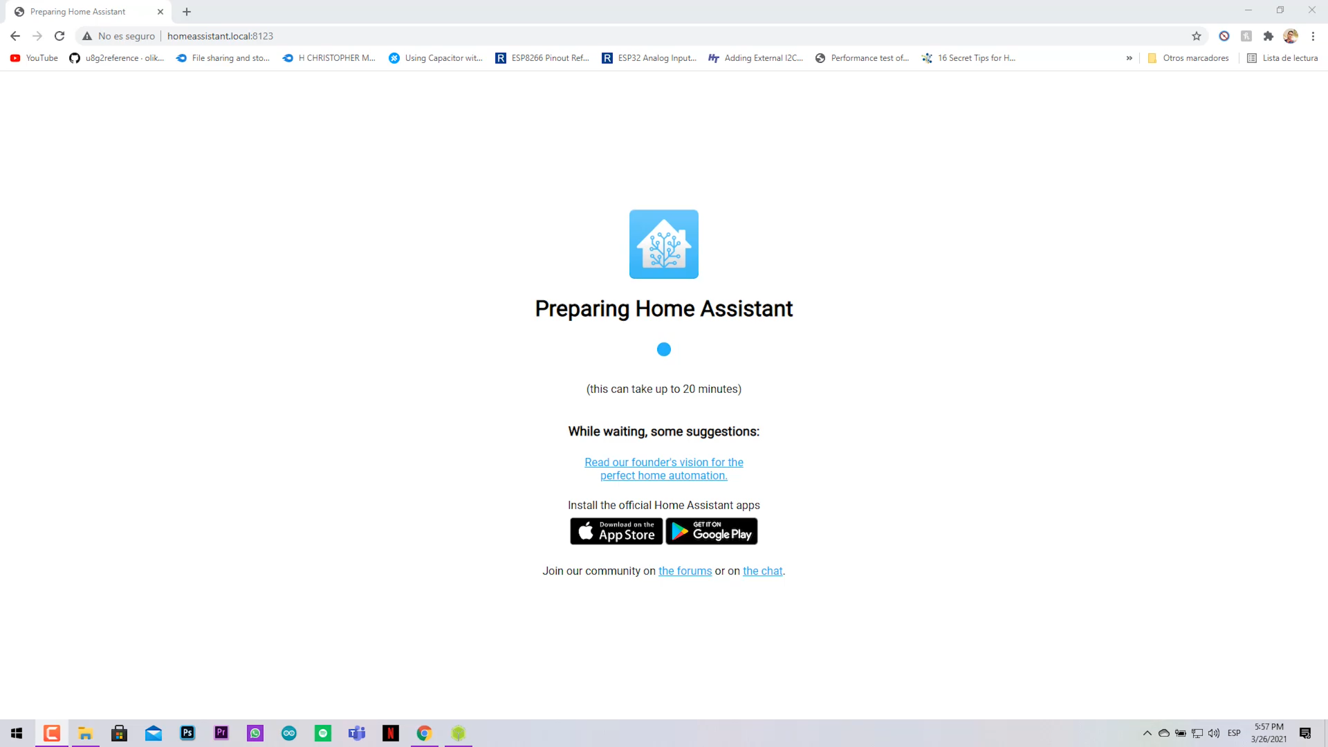
- The page will not work, wait for about a minute and should appear something.
- This new page says that wait for 20 minutes (yes for real 20 minutes).
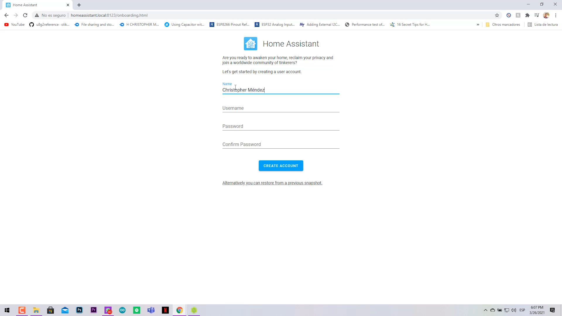
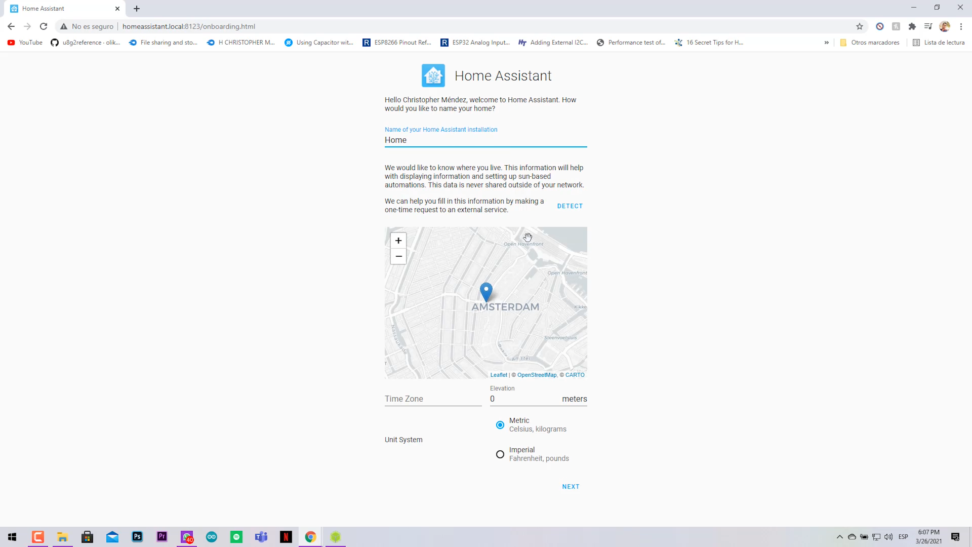
- Then should appear textboxes that you must fill with your personal info.
- Click on create account if you don't have a previus Home Assistant profile backup image.
- Select your location and time zone for better weather predictions.
- Finally finish the process.
ESPHome Configuration
.png)
.png)
.png)
.png)
.png)
.png)
.png)
.png)
.png)
.png)
.png)
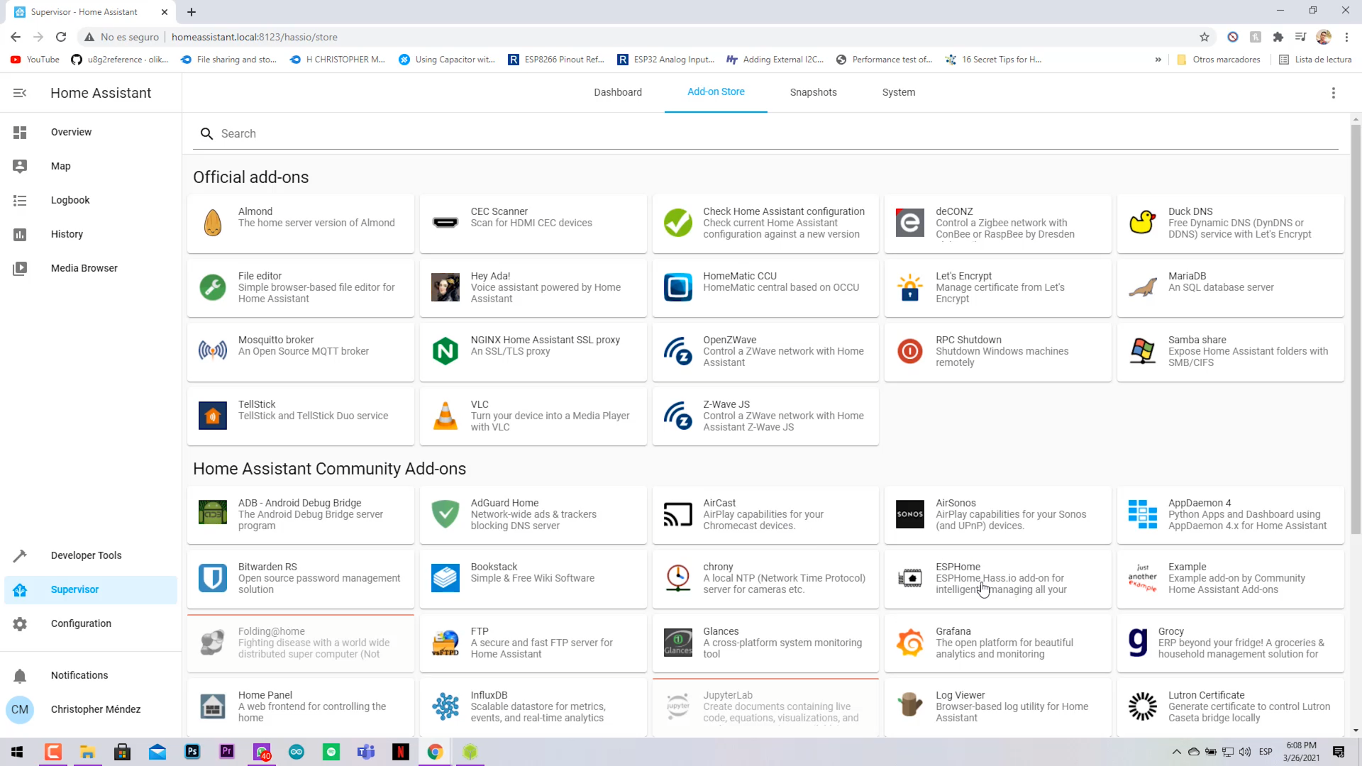
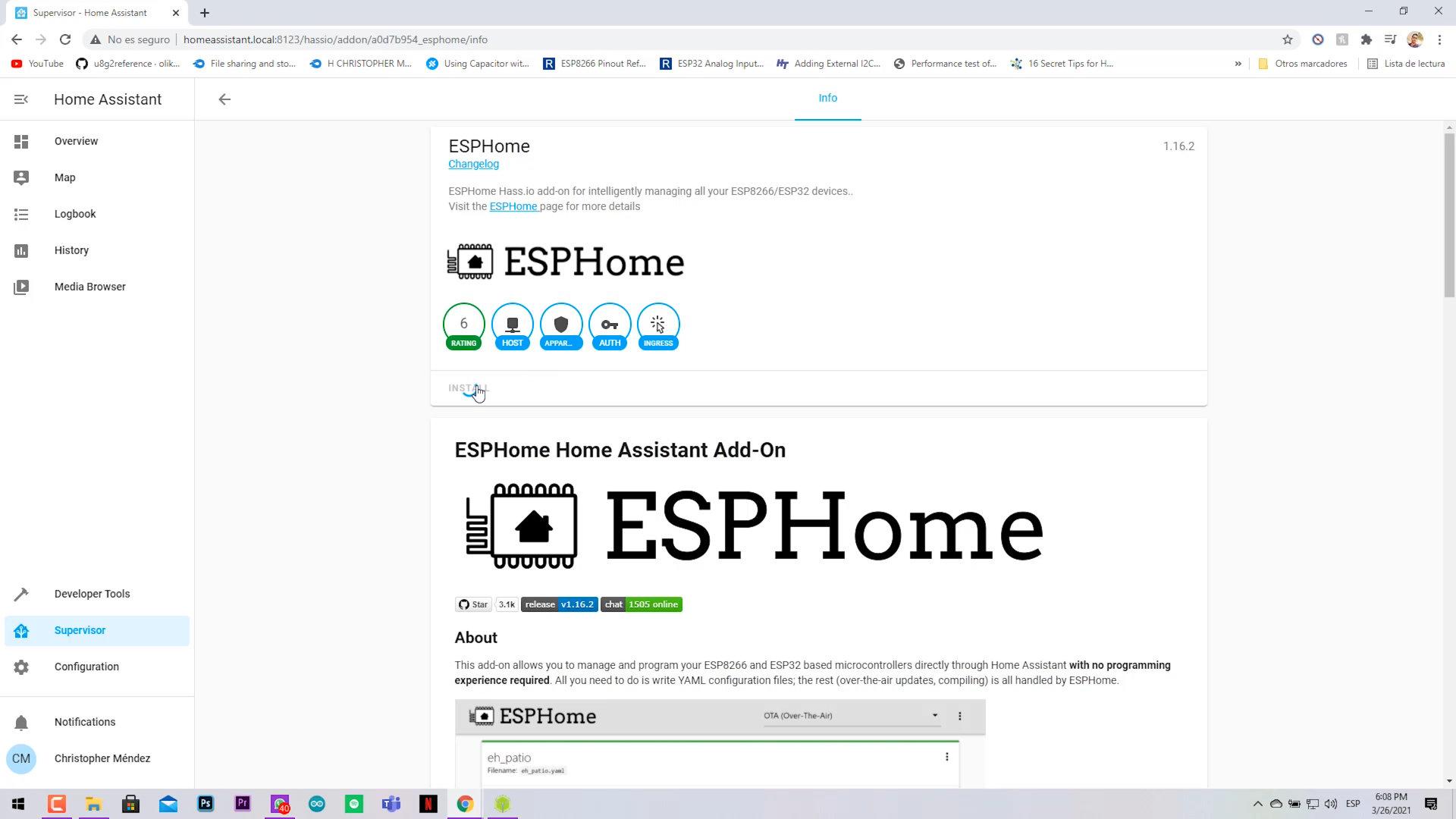
- Once on the Home Assistant home screen, go to Supervisor > Add-on store > ESPHome.
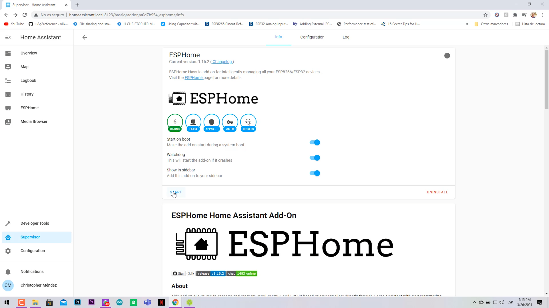
- Install the Add-on, and activate the Watchdog, and Show in sidebar.
- Click on Start.
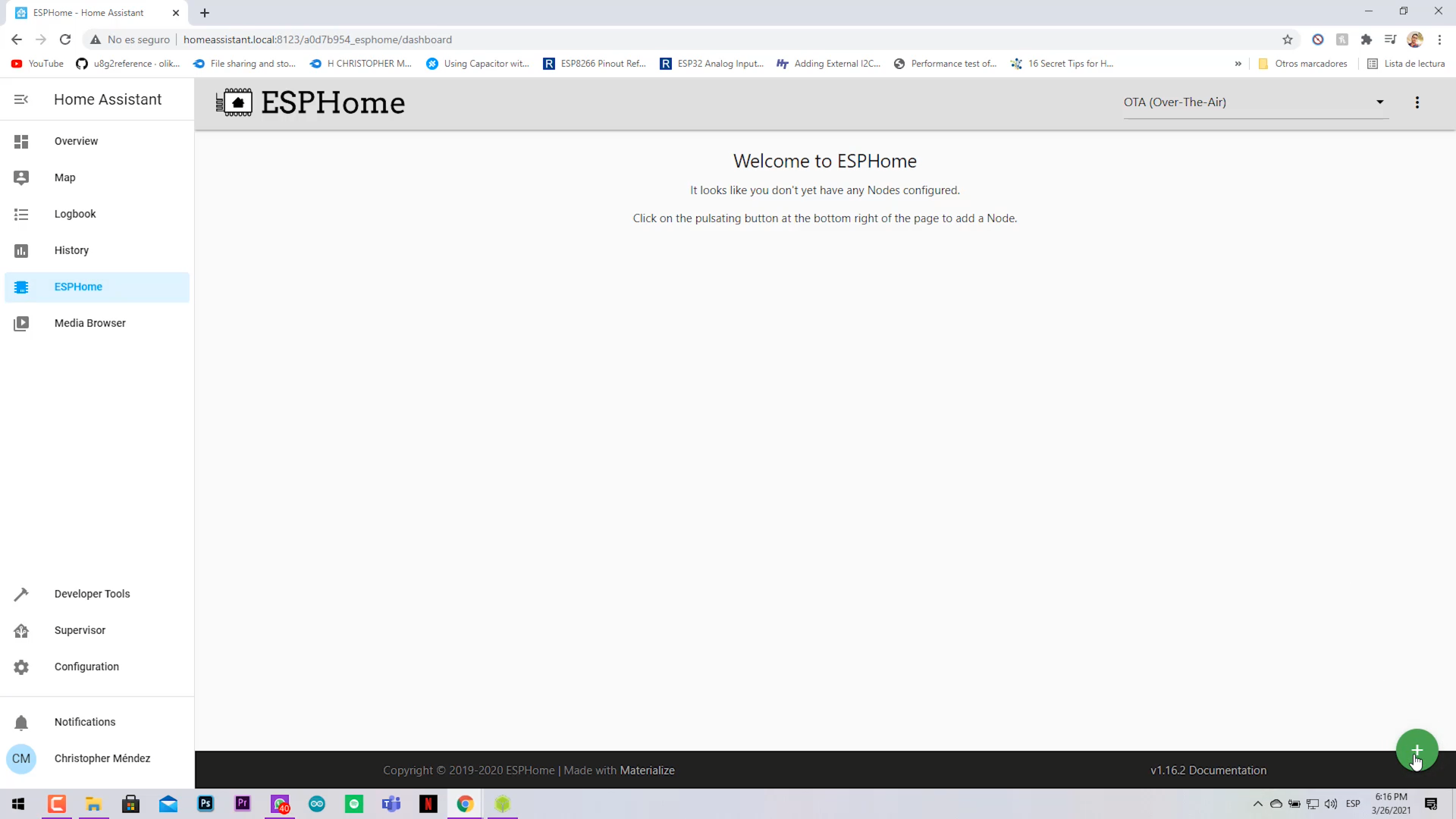
- Click on the ESPhome shortcut in the left sidebar.
- Click on (+) symbol to add a node.
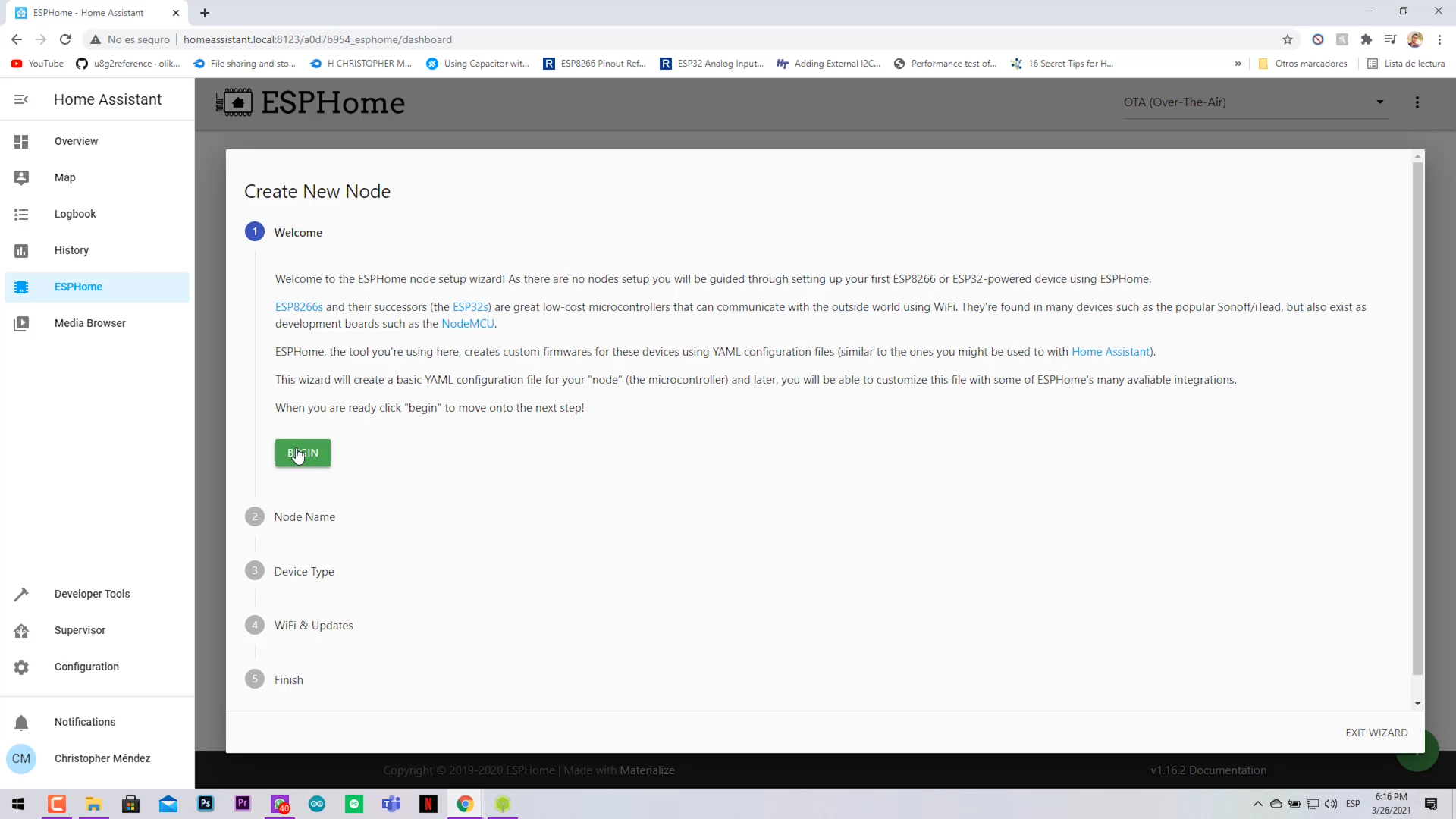
Your first node creation:
- Click on Begin.
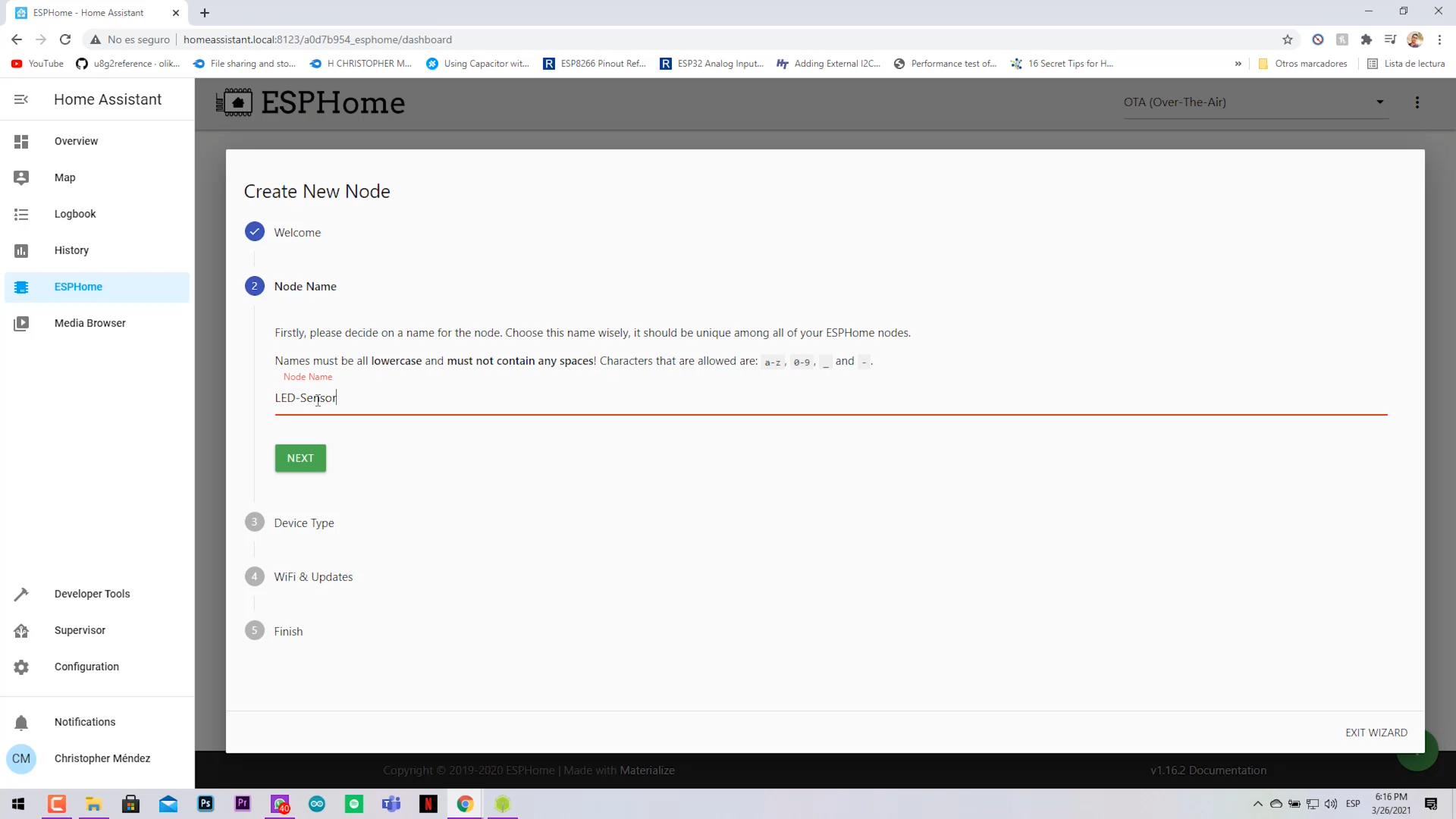
- Name your node with lowercase letters.
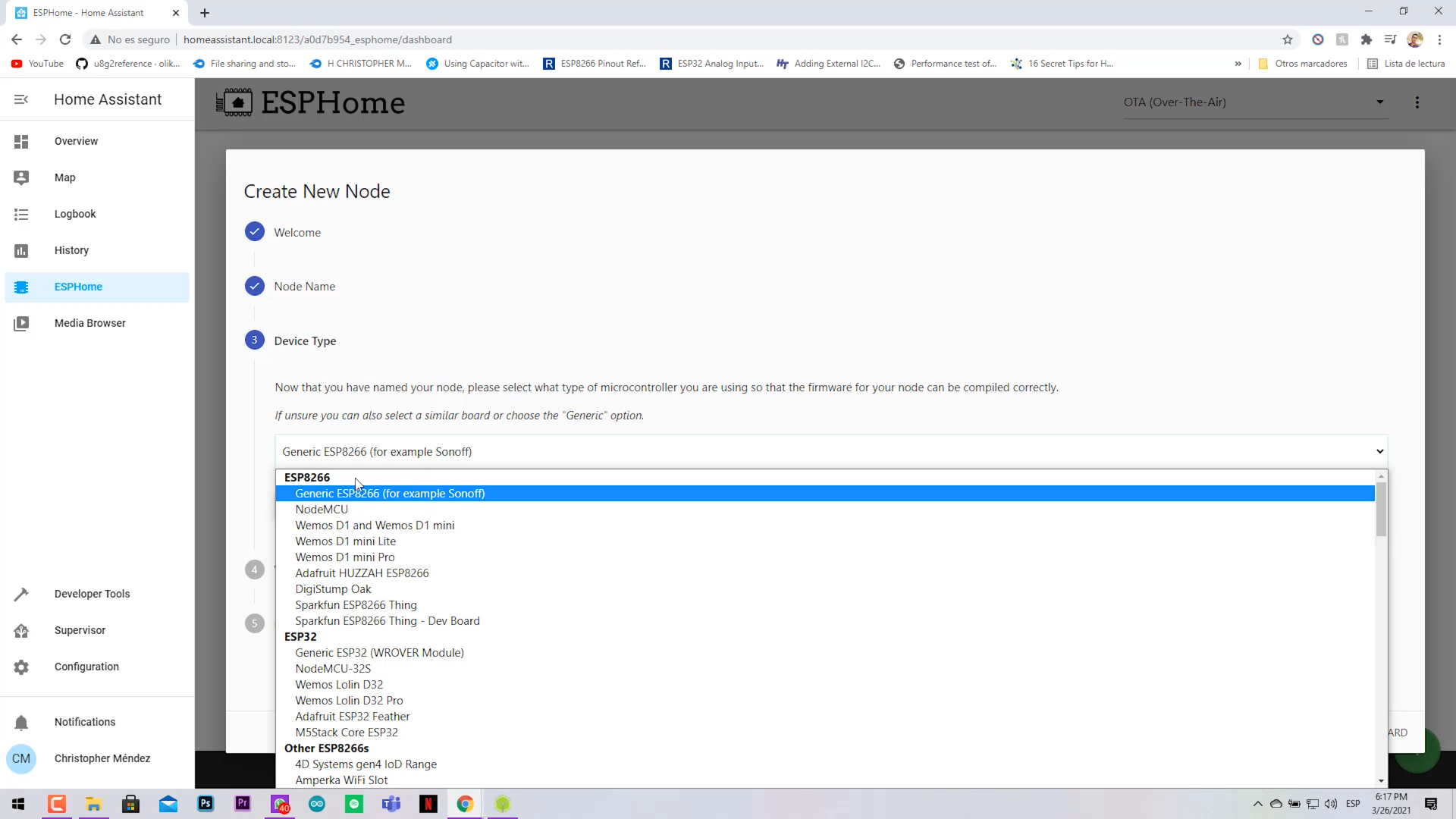
- Select the ESP board you will use (Generic ESP8266) in my case.
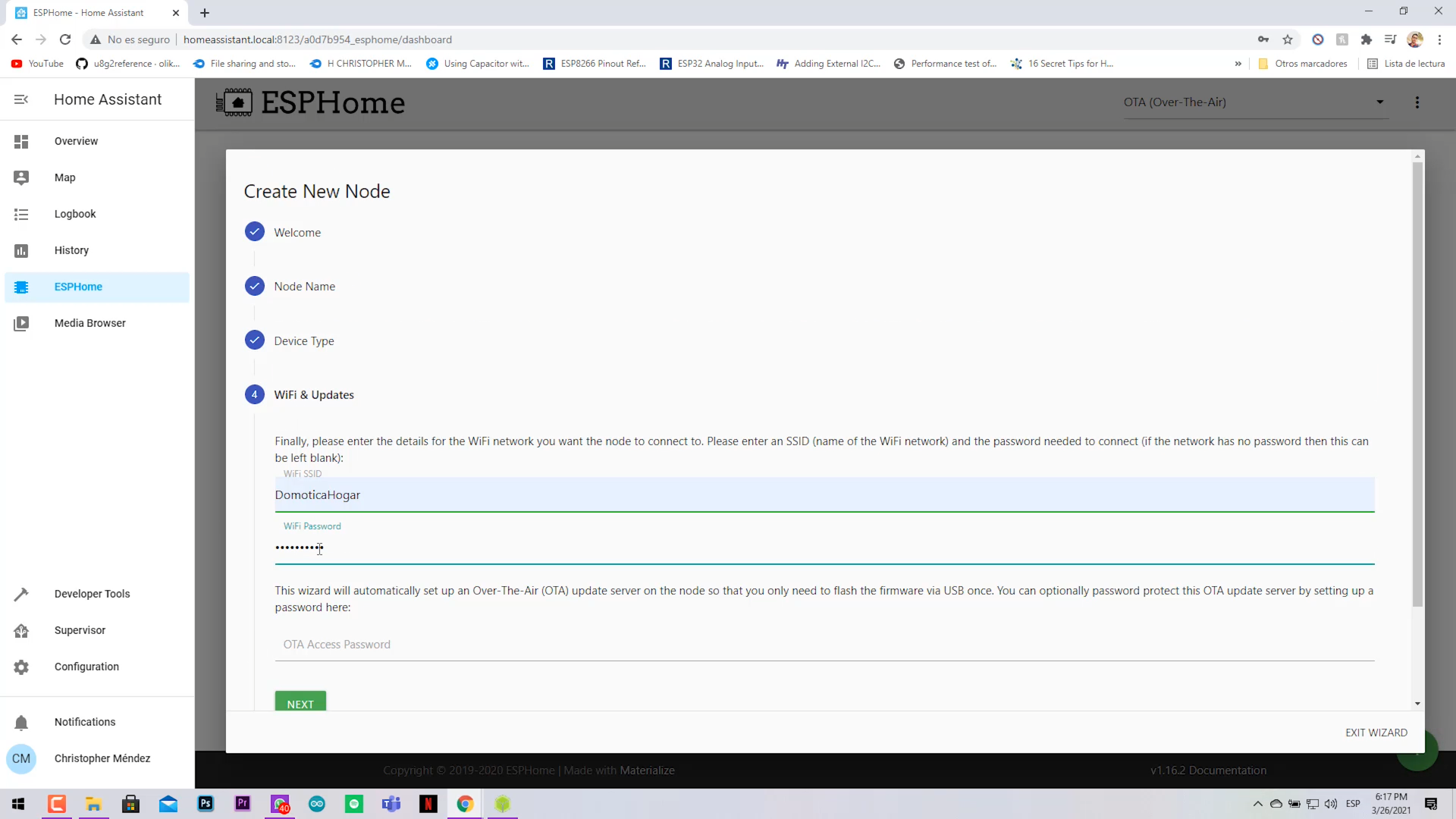
- Next, insert your WiFi credentials.
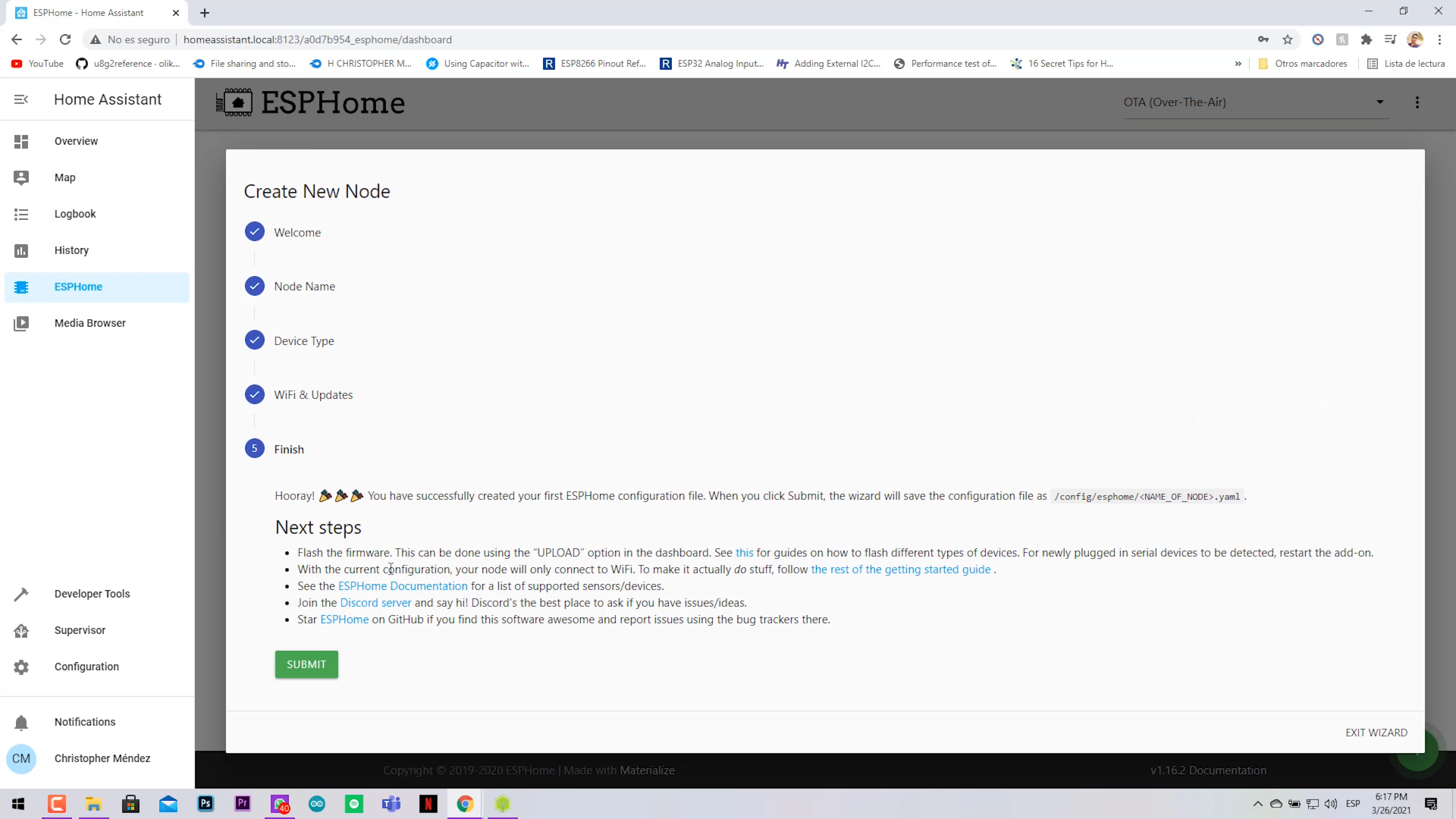
- Click on Submit.
- Now your node is created with some initial codes. (Do not edit them if you don't know what are you doing).
Your First Node Creation (IoT Project Binding)
.png)
.png)
.png)
.png)
.png)
.png)
.png)
.png)
.png)
.png)
.png)
.png)
.png)
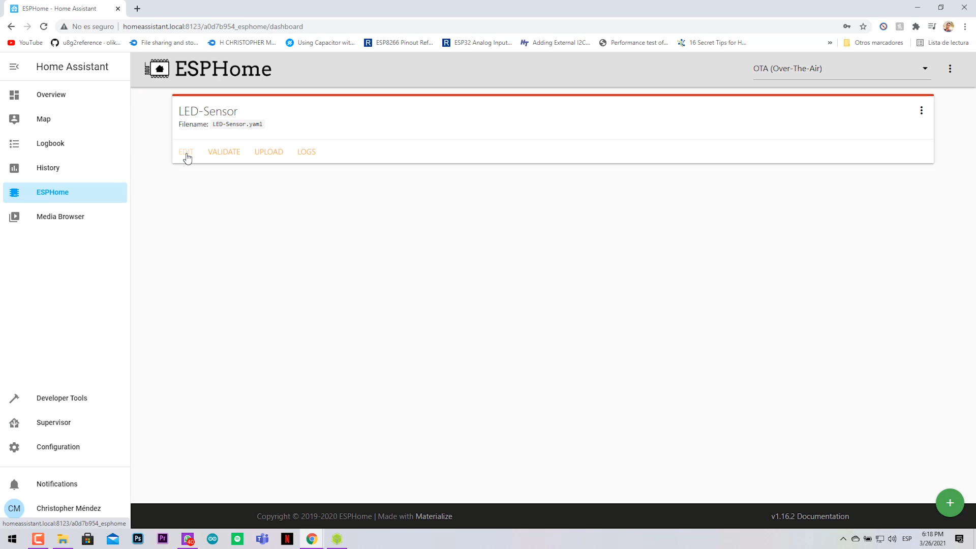
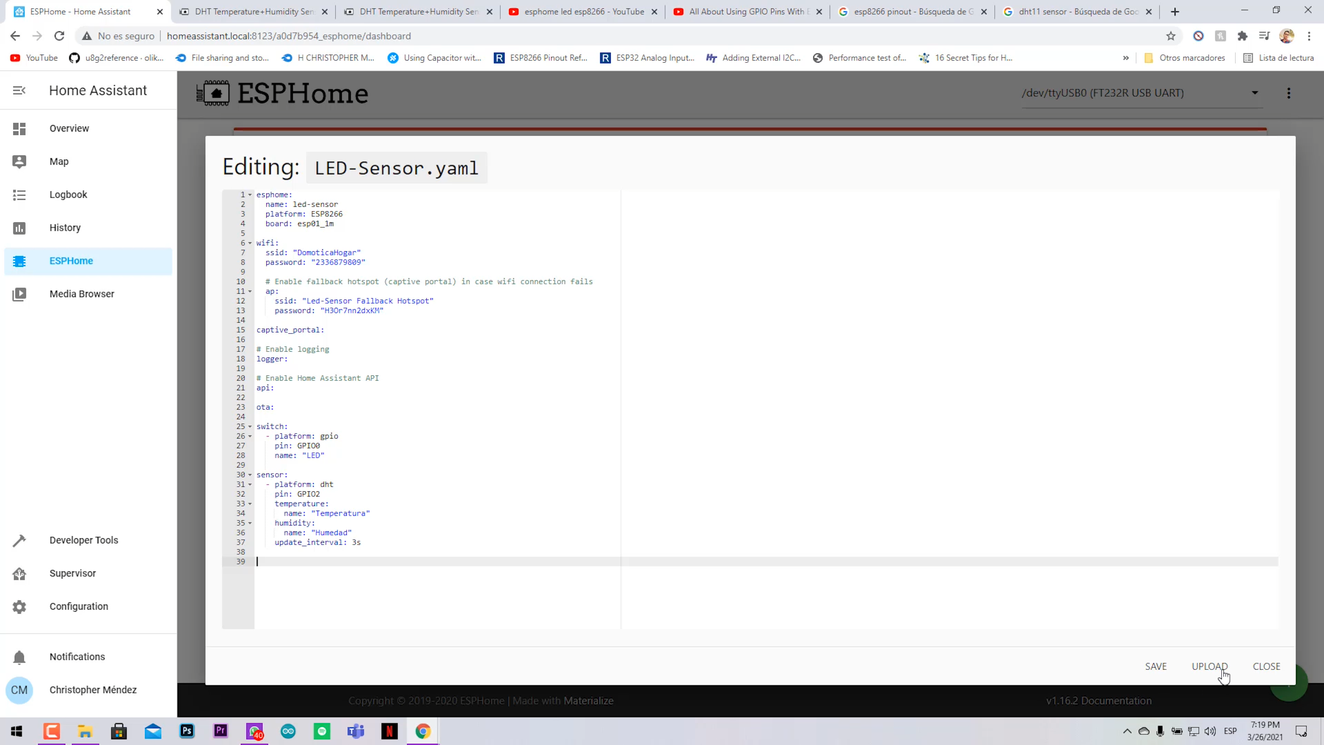
- Go to ESPHome main webpage
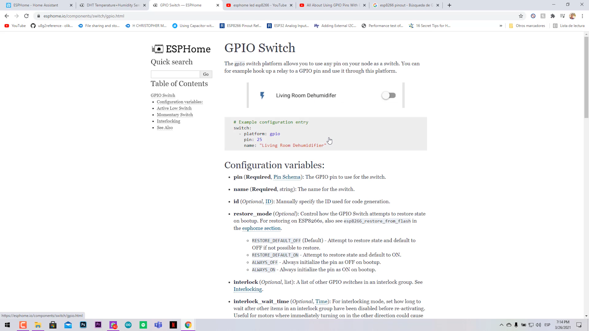
- Find the GPIO Switch example
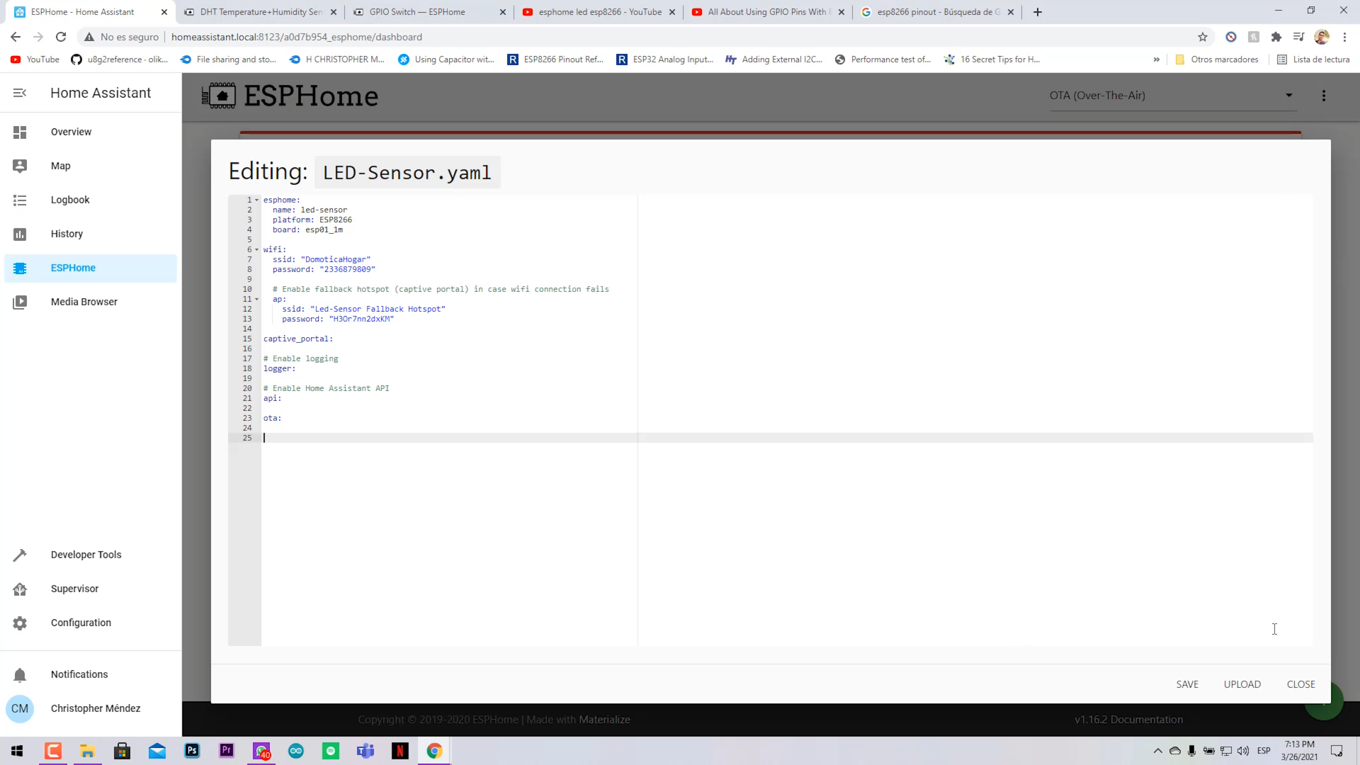
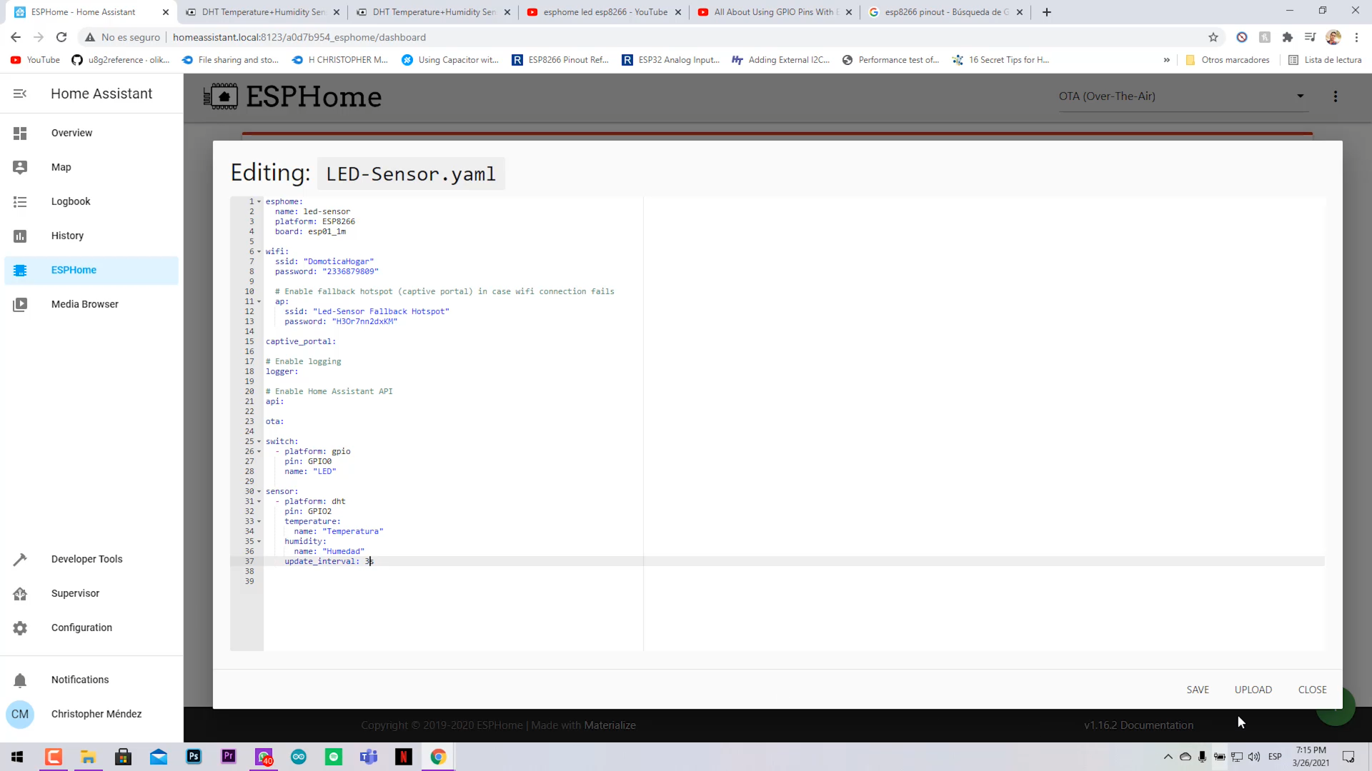
- Copy the example and paste it below the initial code of your Node. Changing the pin and name to GPIO0 and LED.
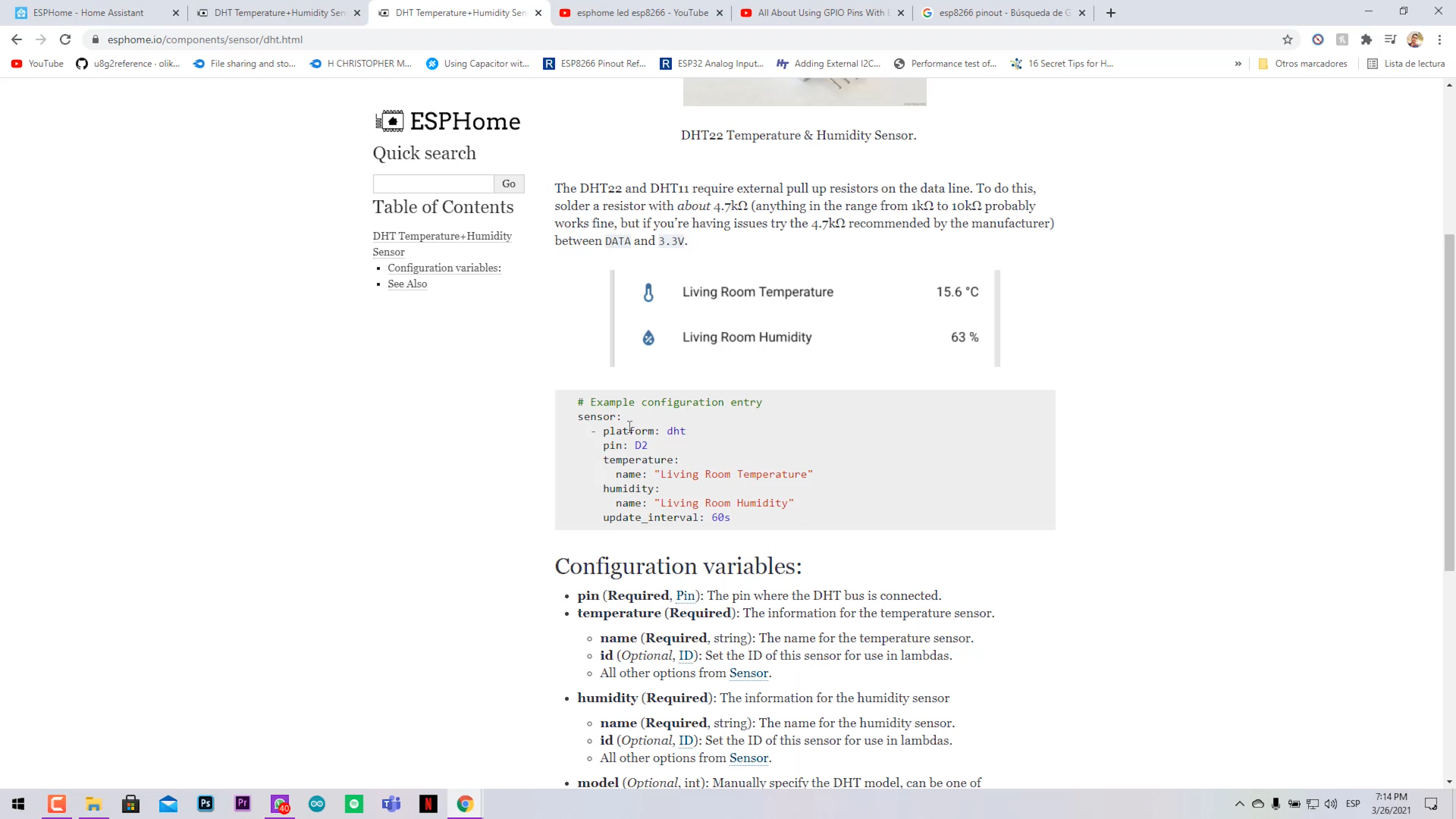
- Find the DHT11 sensor example.
- Copy the example and paste it below too, changing the pin to GPIO2.
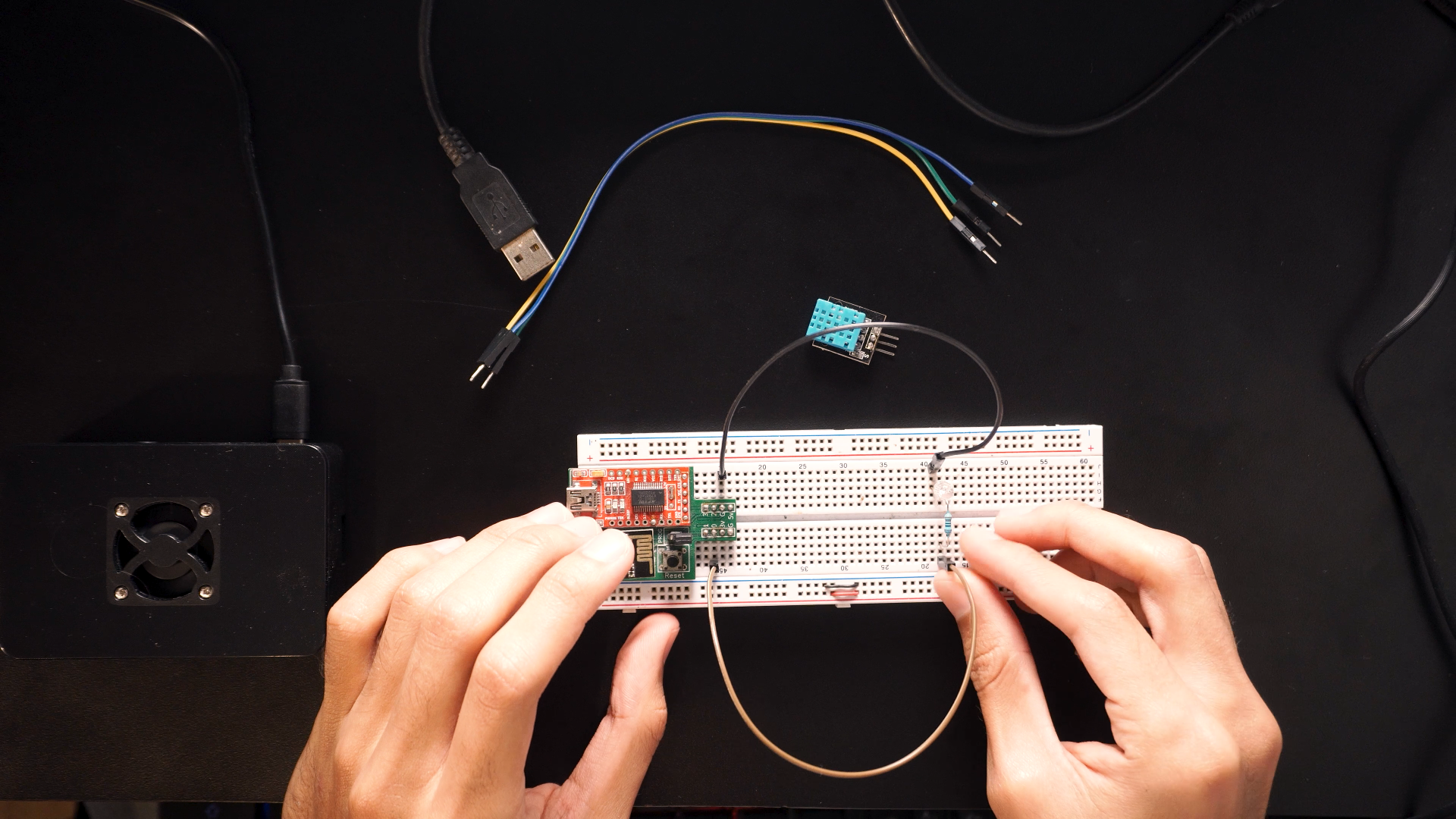
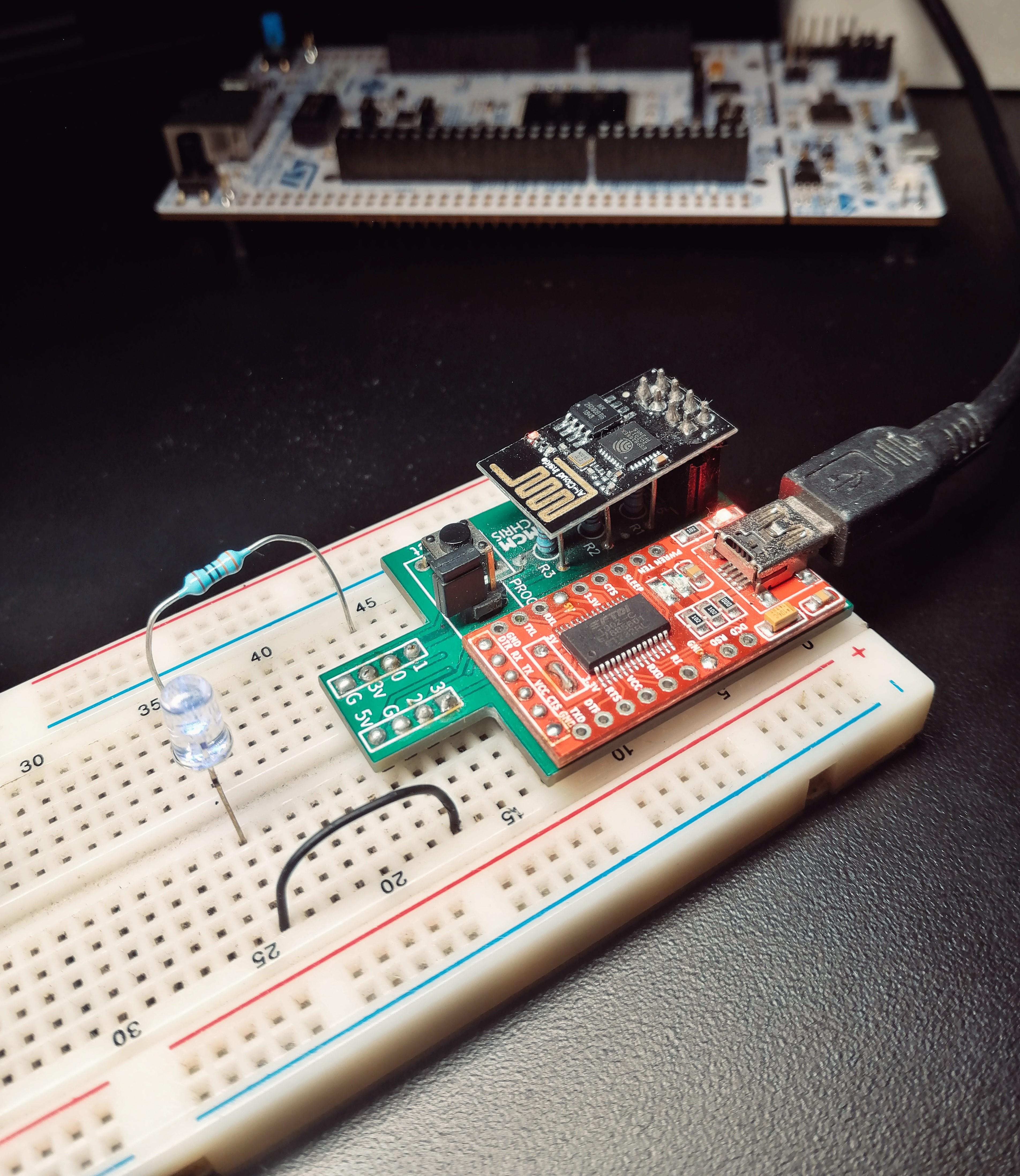
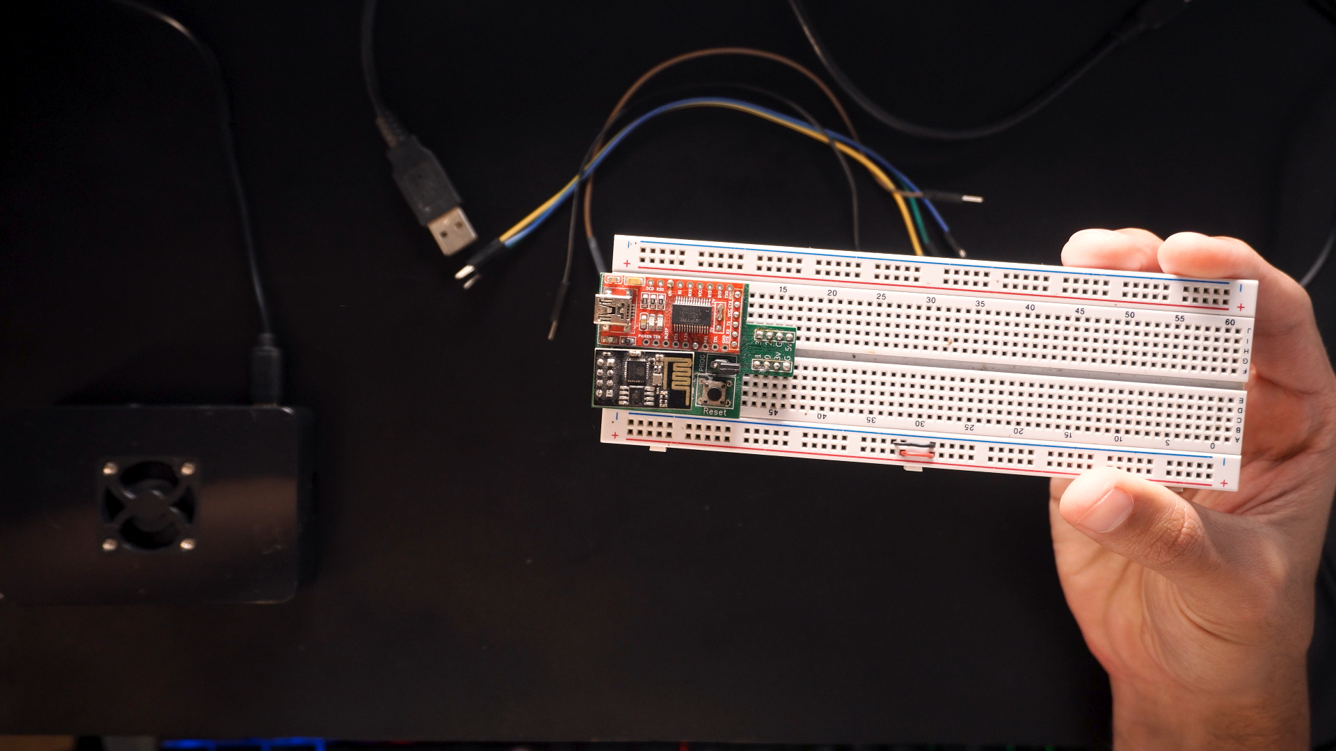
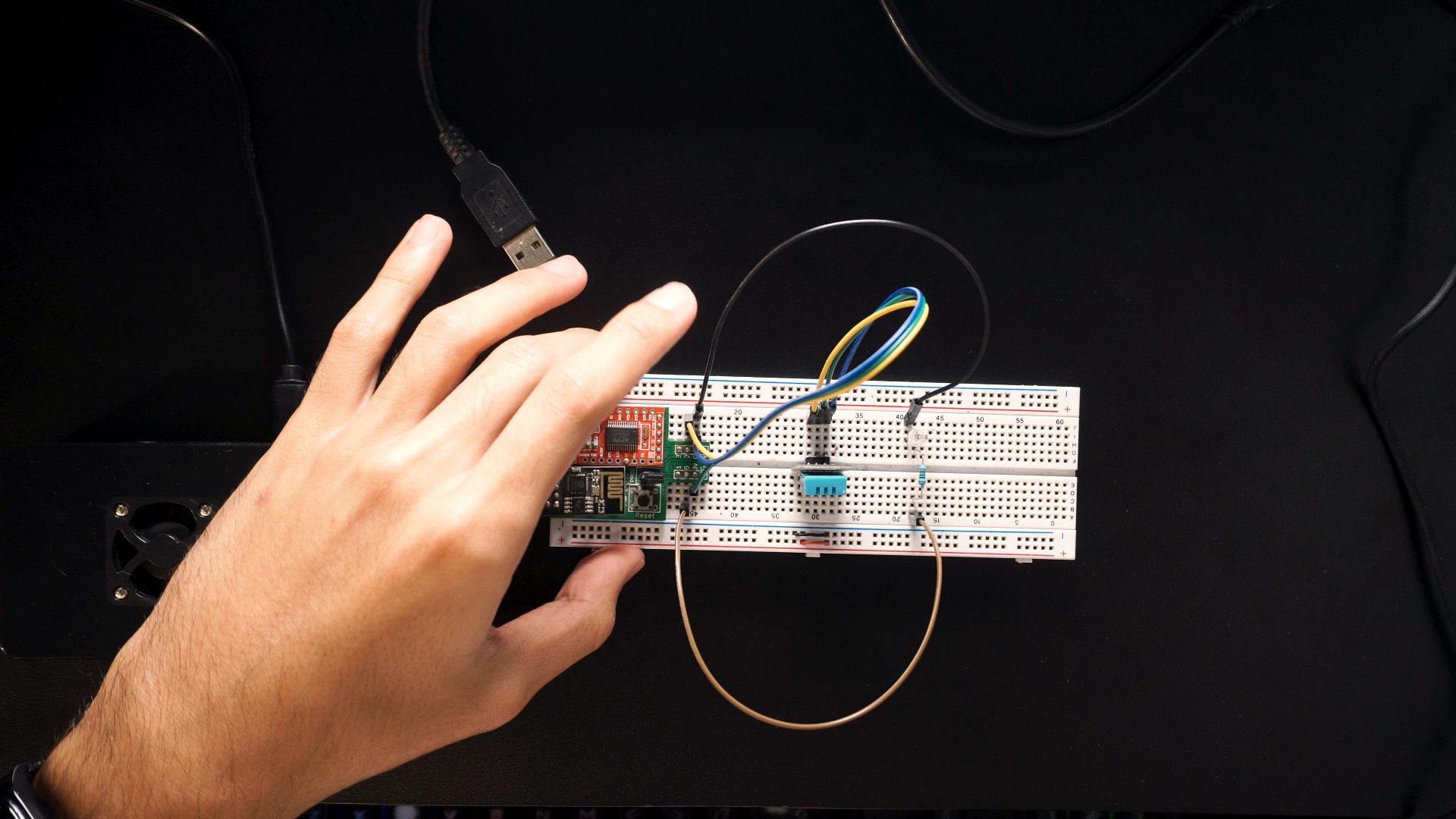
Assamble the circuit in the breadboard as shown.
- Connect the LED with it 220 ohm resistor between GPIO0 and GND.
- Connect the DHT sensor (Vcc to 3.3v, GND to GND, and Signal to GPIO2).
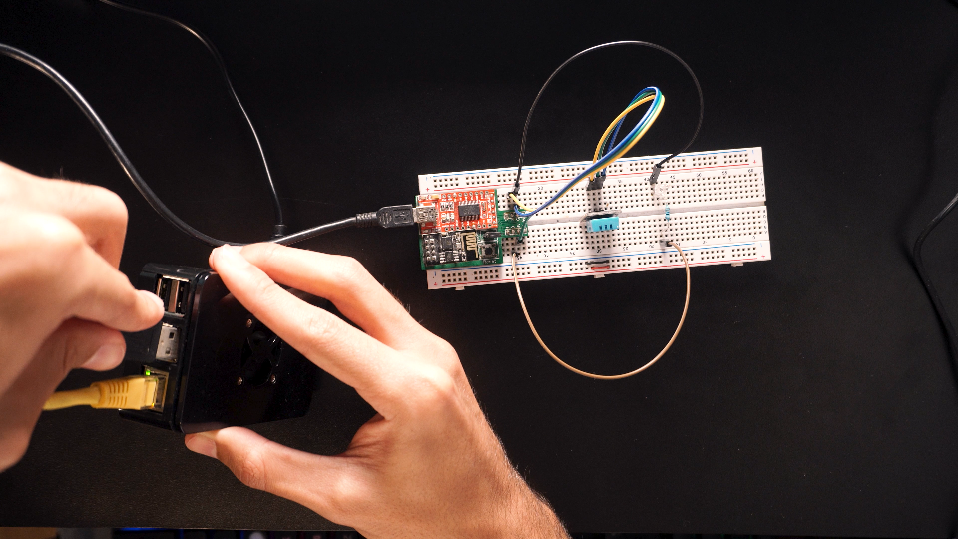
- Connect the USB cable from the flasher board to the USB port of your Raspberry.
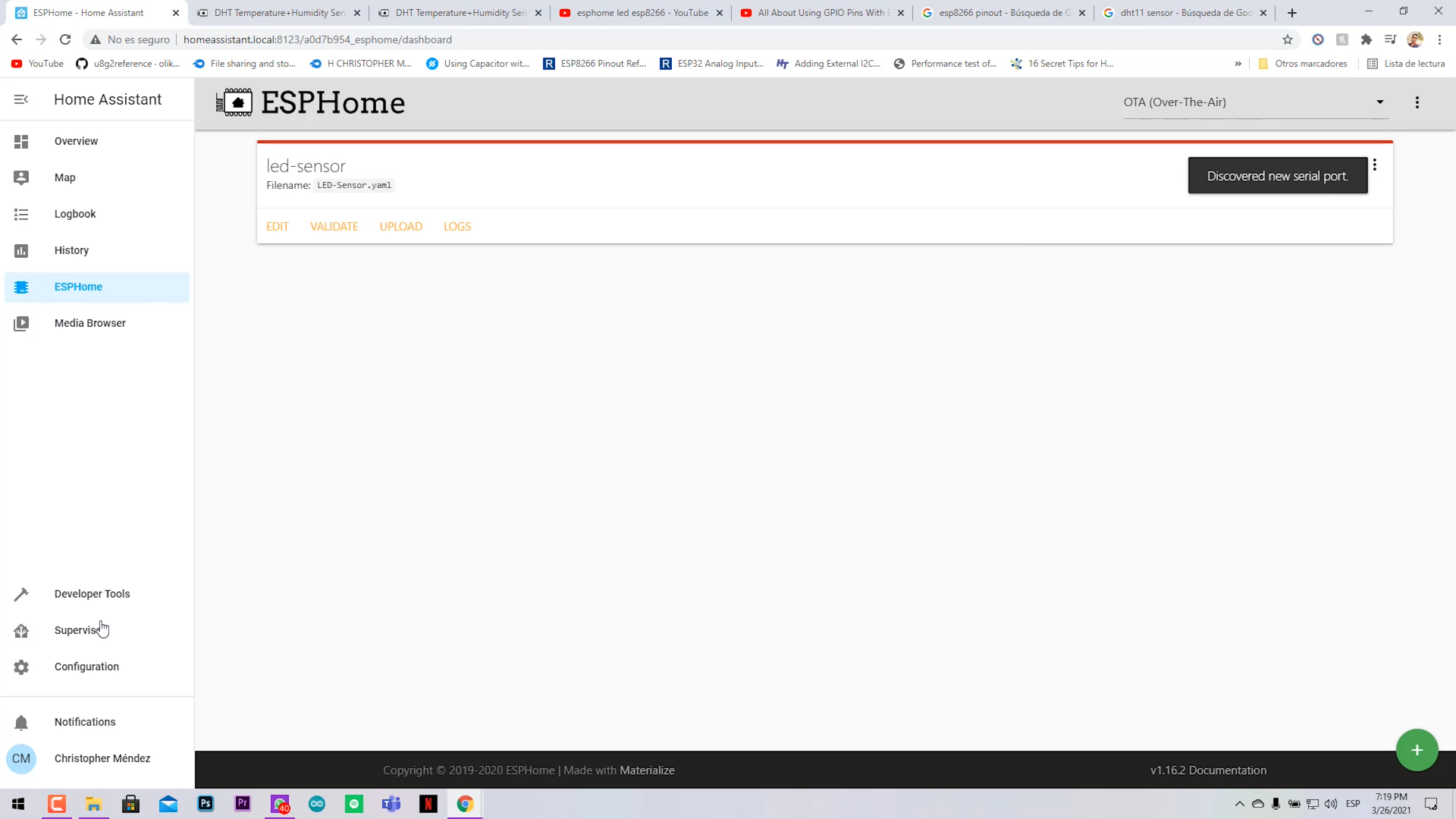
- The Raspberry will detect a new serial port.
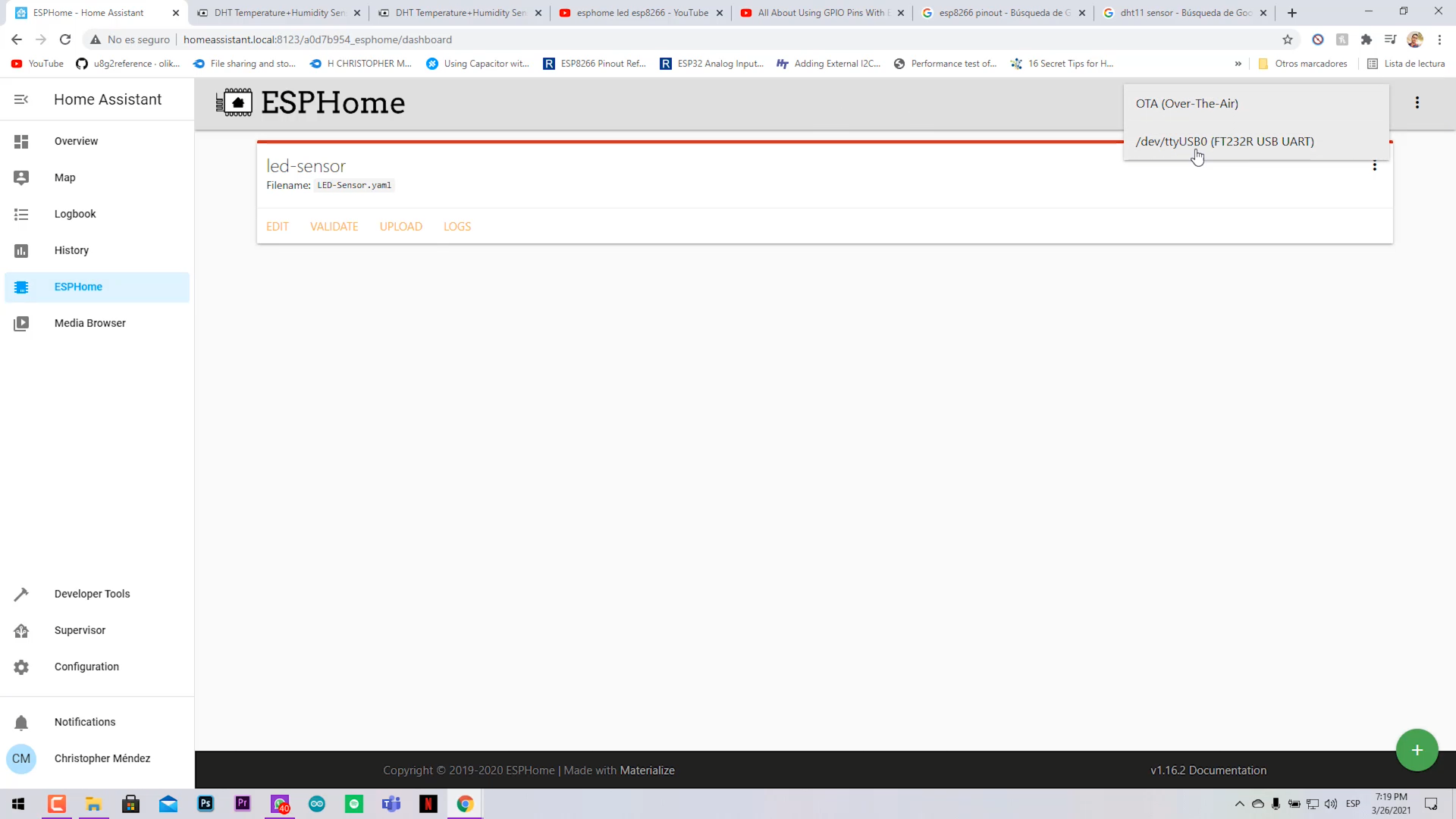
- In the right upper corner select the USB serial port.
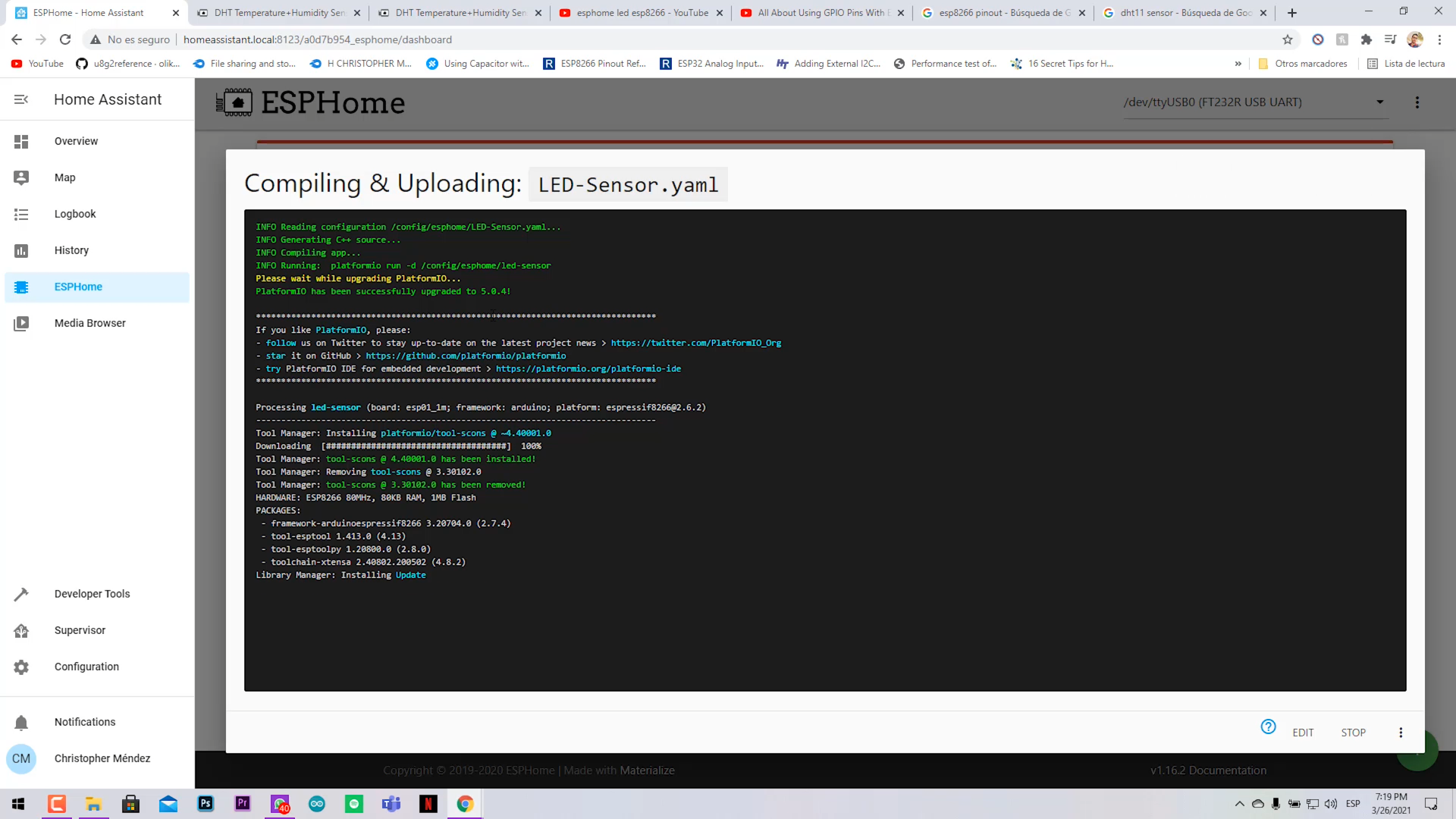
- Upload your code to the ESP8266.
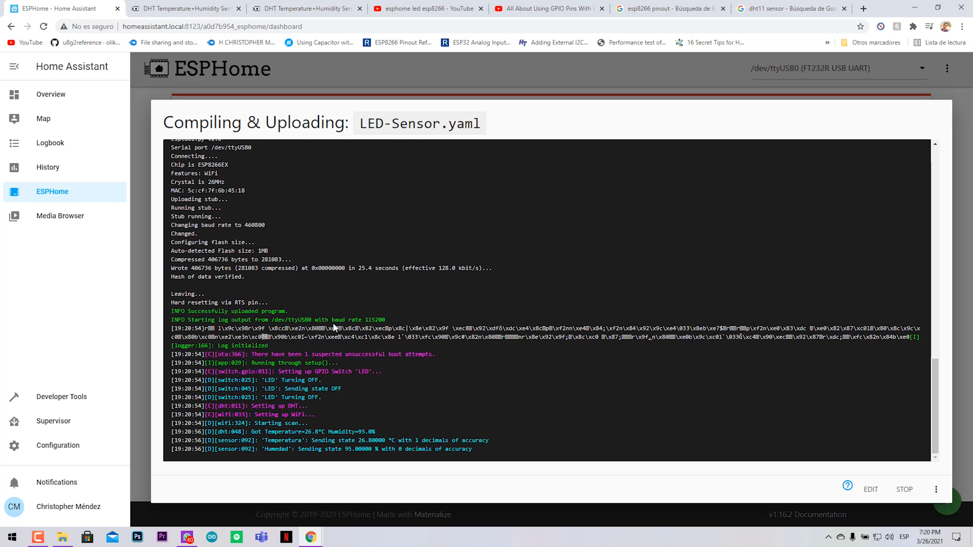
- You should see a black cmd like screen showing the debug of the upload process.
- Then you should see on blue color the data return of LED state, temperature and humidity.
We are almost done.
Setting Your Dashboard to Visualize the Data and Control the LED
.png)
.png)
.png)
.png)
.png)
.png)
.png)
.png)
.png)
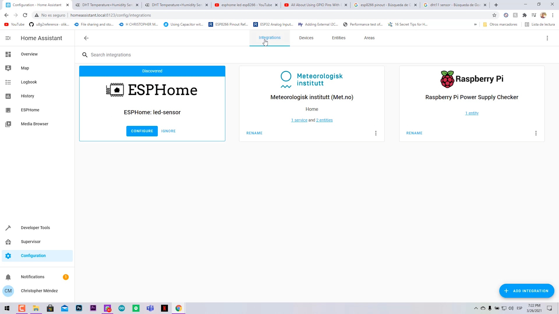
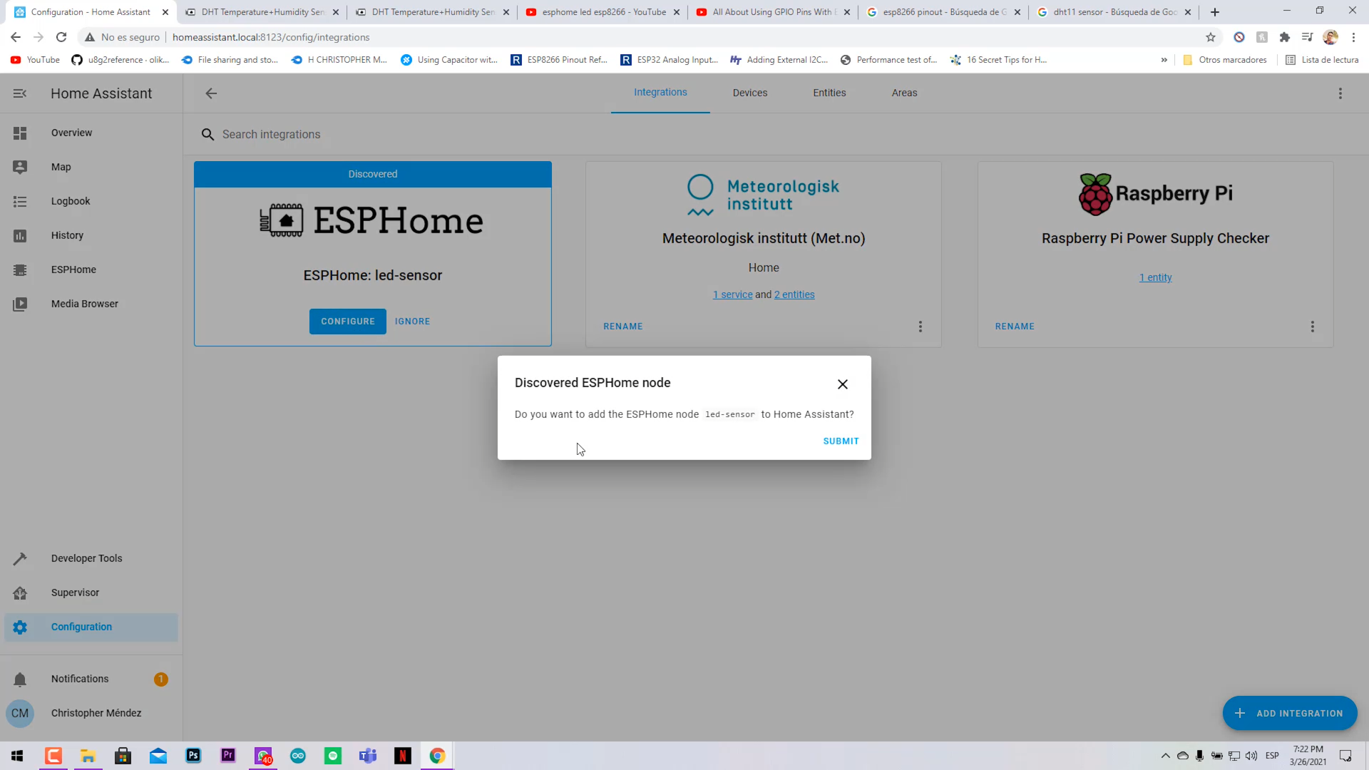
- Go to Configuration > Integrations and you should see a new widget telling you that is a new discovered device.
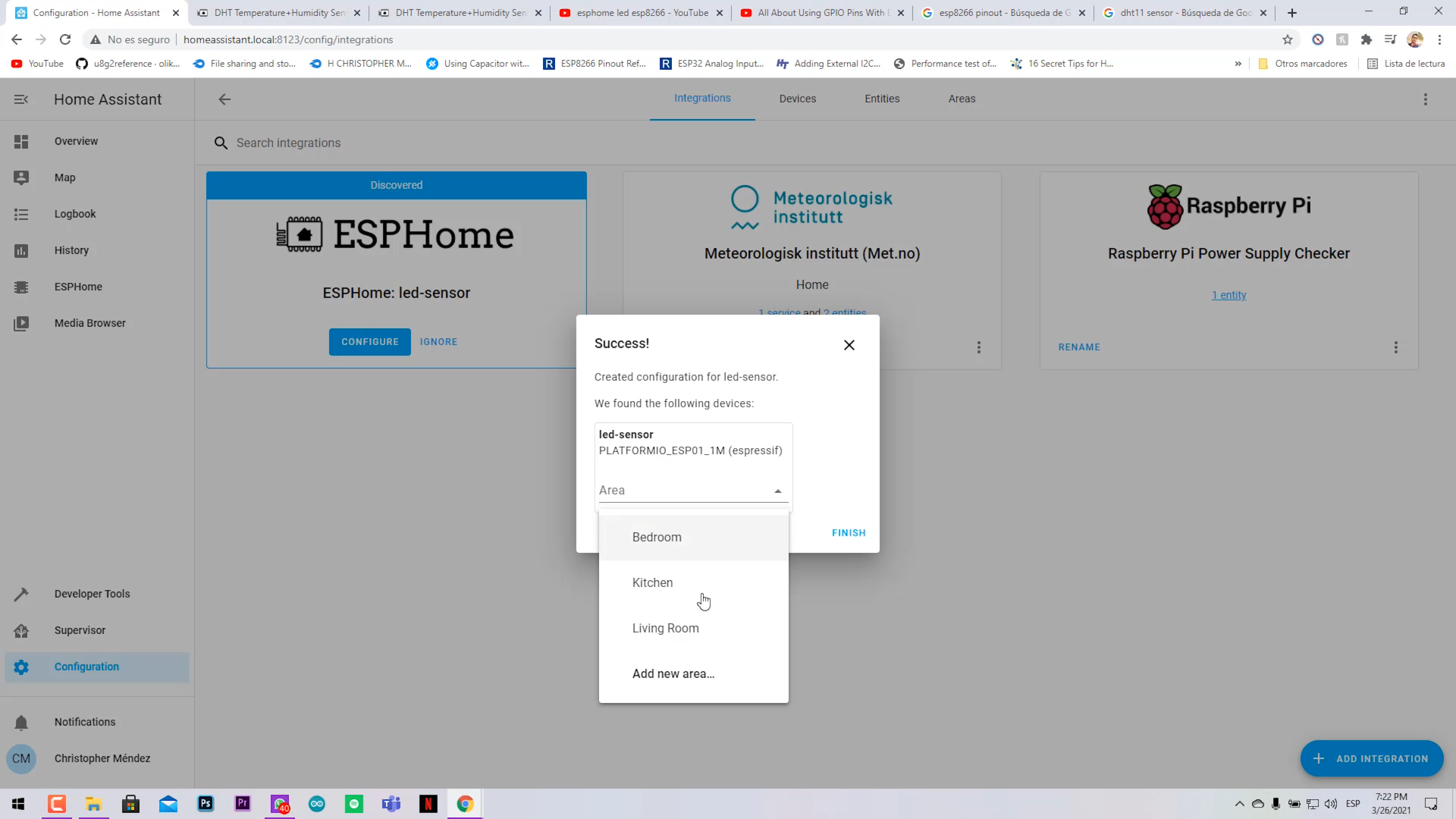
- Click on configure > submit > select house zone and finish.
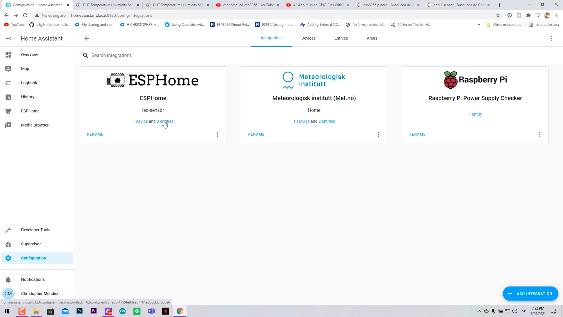
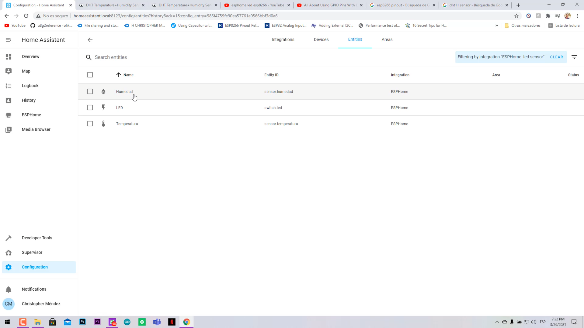
- Now verify that the new integration has our 3 devices (LED, Temp and humidity).
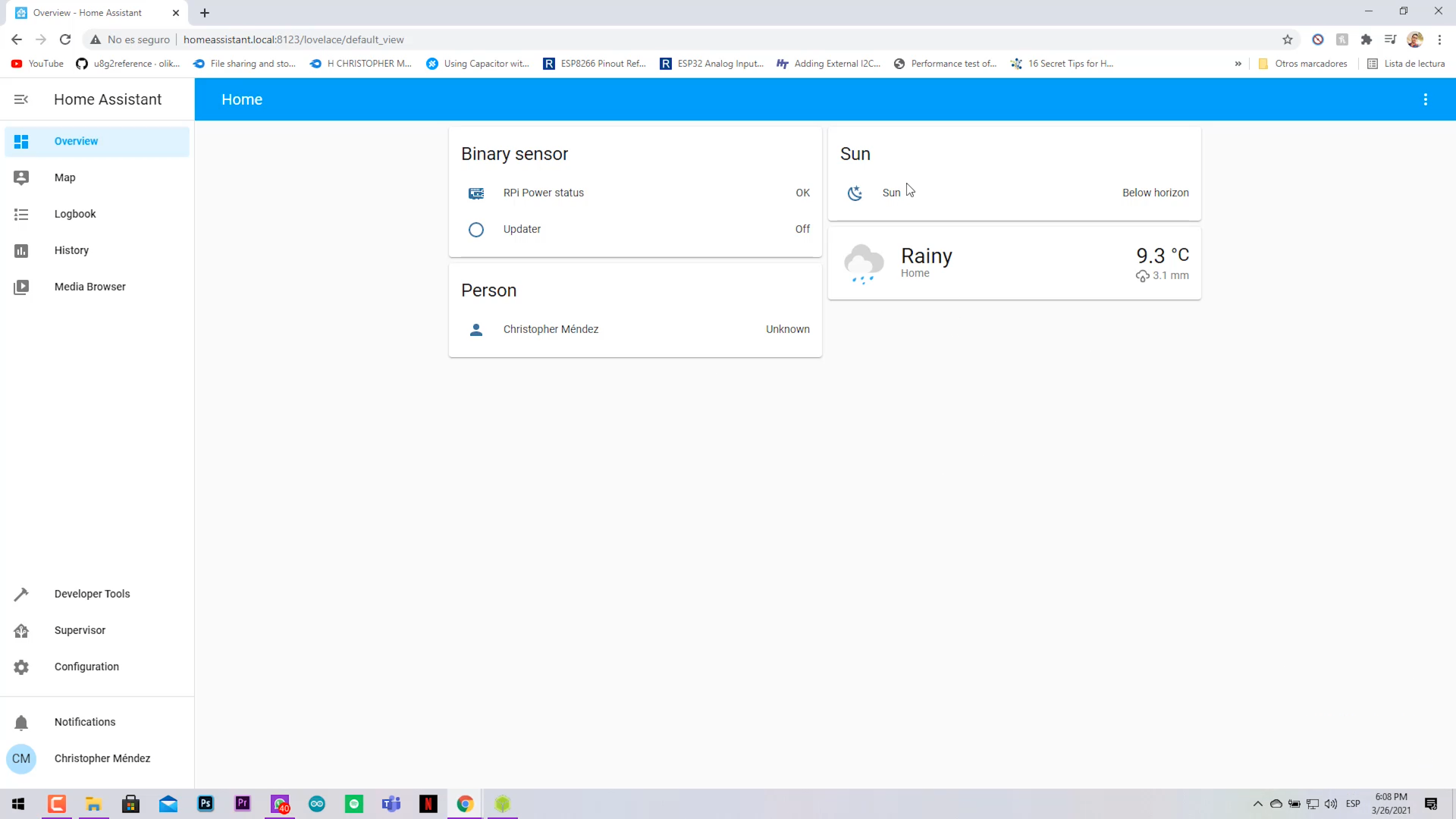
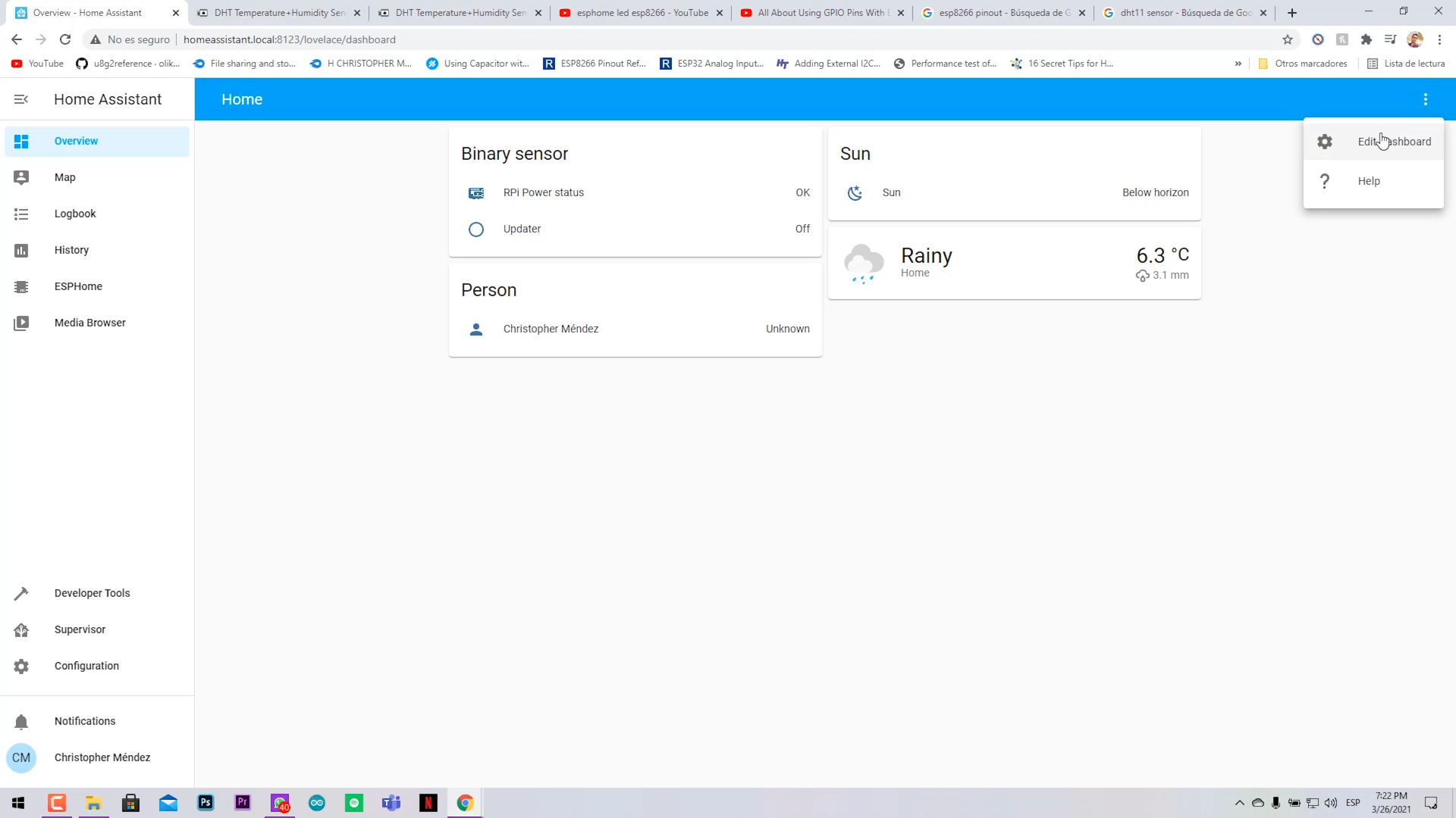
- Go to the main page (Overview).
- In the right upper corner on the 3 dots, select "Edit dashboard".
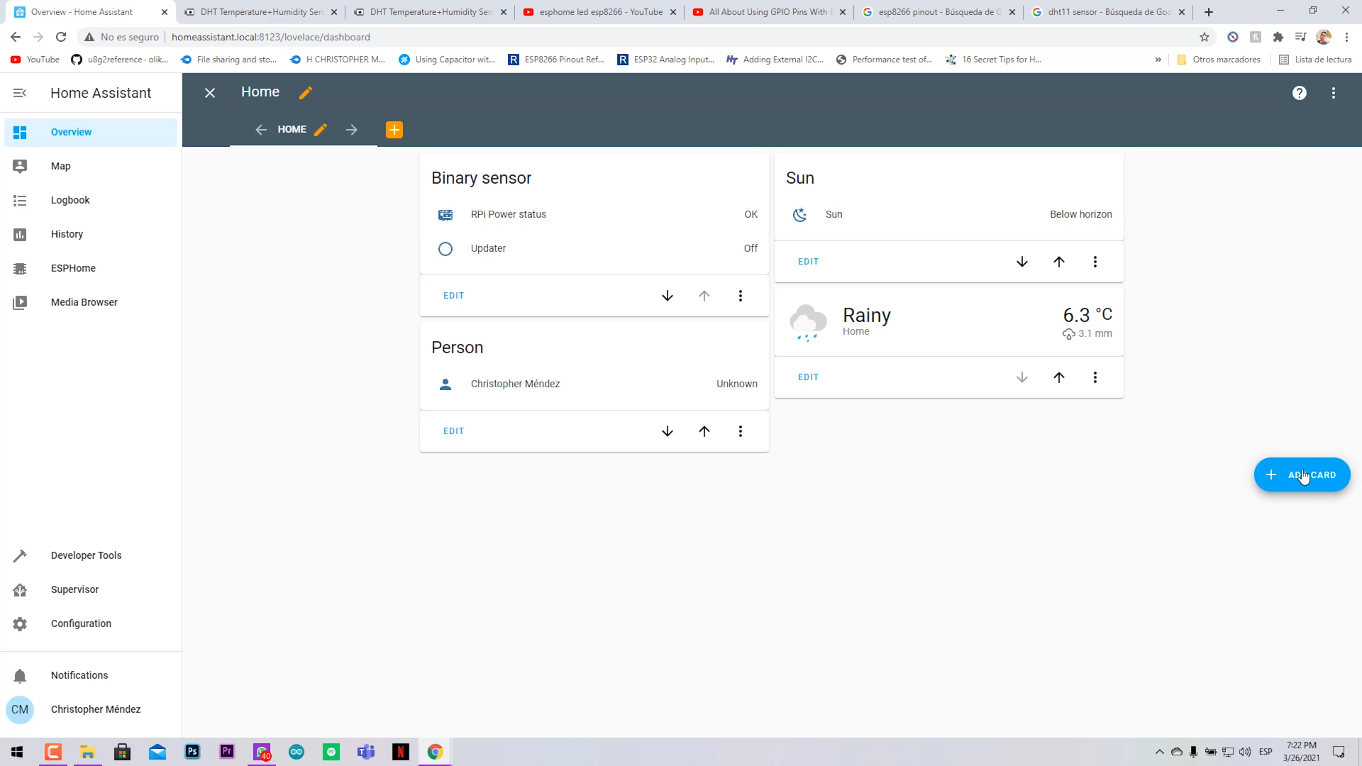
- Click on (+) Add Card.
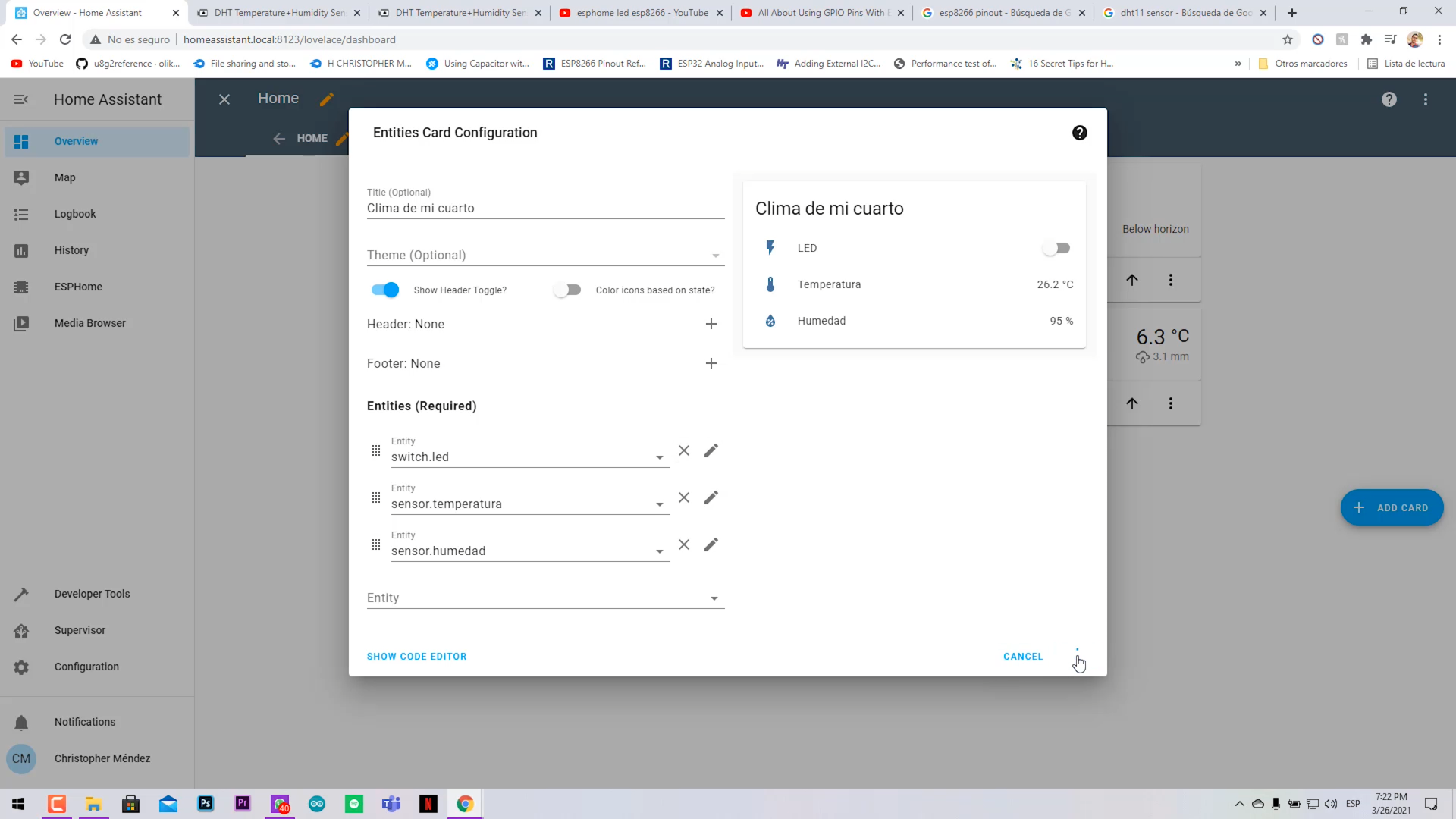
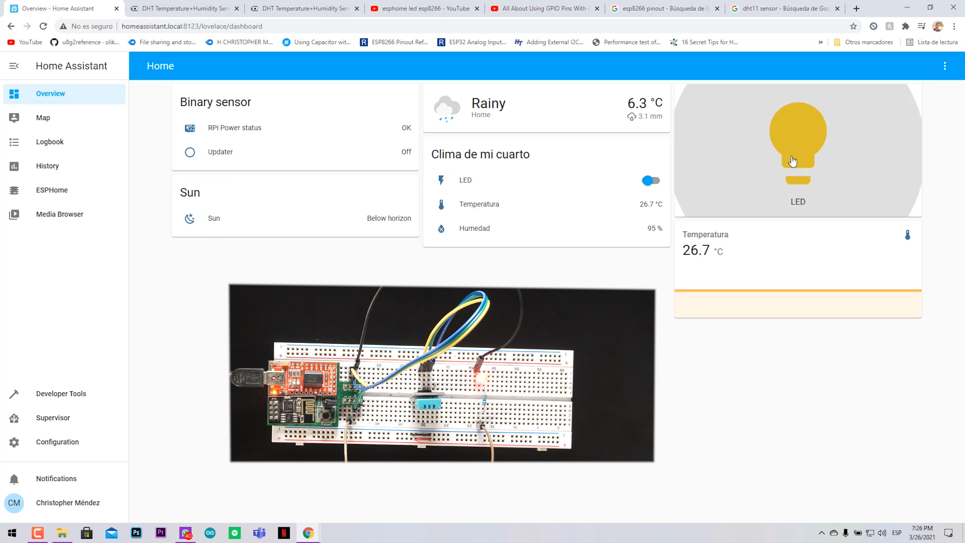
- Select the card of your preference that shows the data of the sensor and the toggle switch for the LED.
- Name it as you want, in my case "Clima de mi cuarto".
- Now everything is ready.
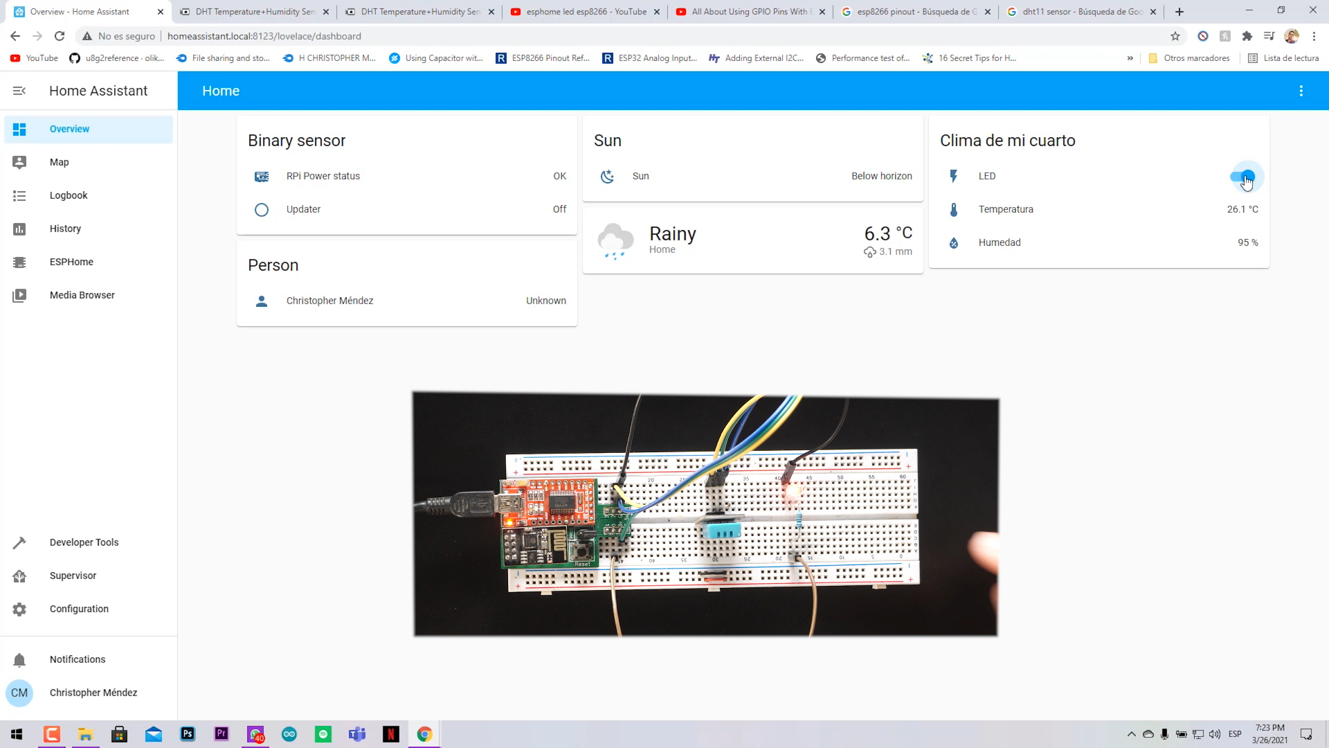
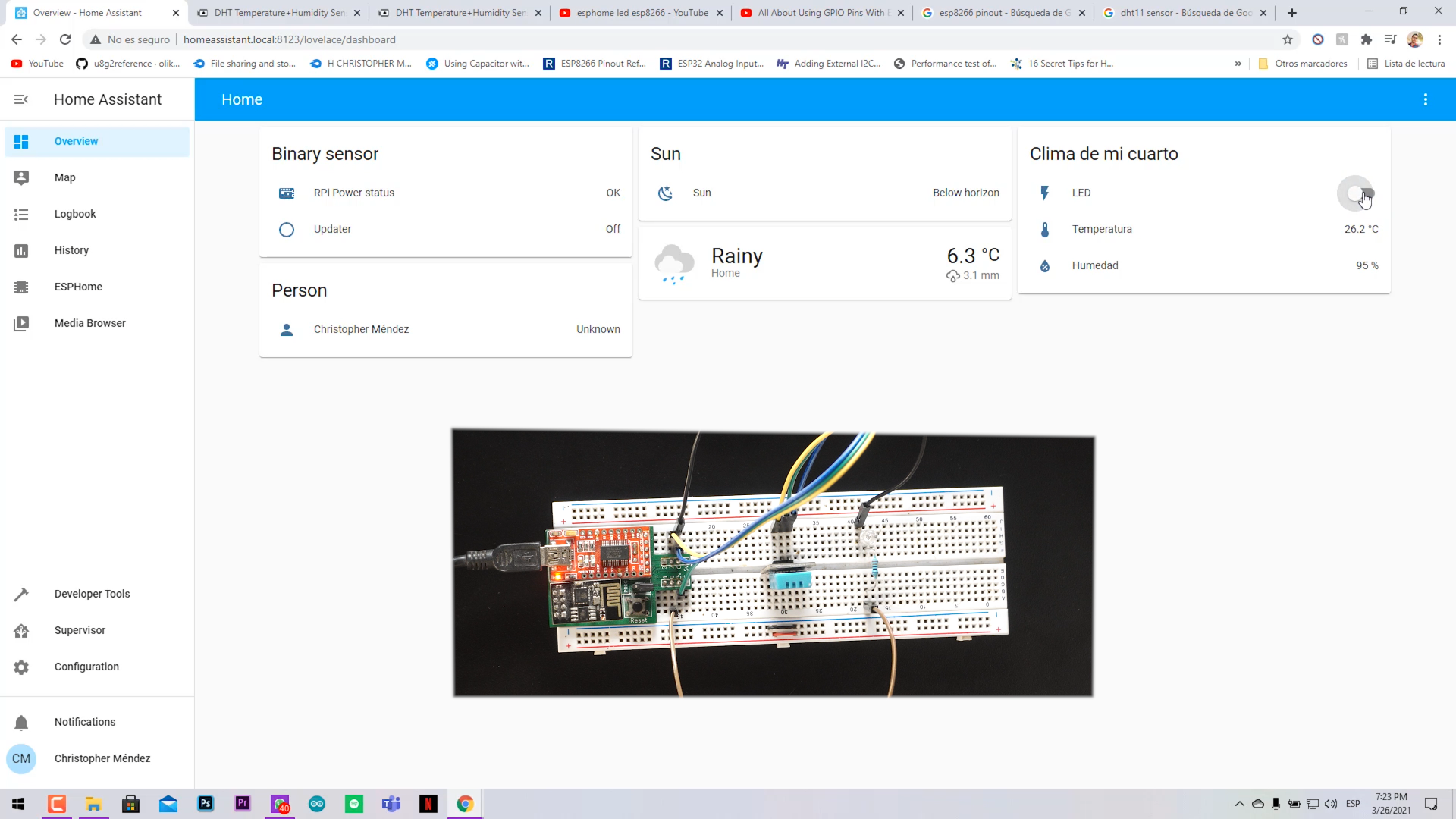
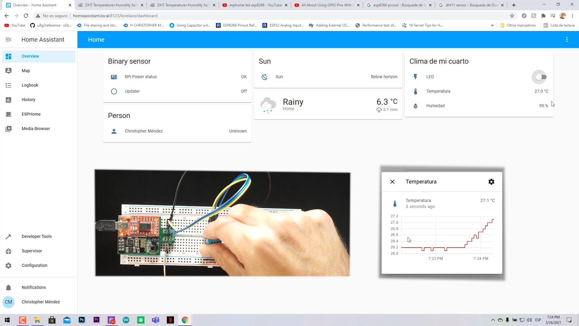
Final Test! Enjoy Your Project
.png)
.png)
.png)
.png)
Now you should be able to control your hardware from anywhere in your LAN home network.
You can disconnect your ESP8266 from your Raspberry and power it with batteries or a wall power brick and it will be completely functional.
Great thing!! You can modify and reflash the ESP code Over the Air, without having to connect it directly by USB to the Raspberry Pi.