How to Solder Your FumeFan PCB KIT / Any PCB KIT
by hertzgamma in Circuits > Electronics
2308 Views, 18 Favorites, 0 Comments
How to Solder Your FumeFan PCB KIT / Any PCB KIT
You probably are one of the amazing people who supported our Kickstarter campaign - The fumeFan. If you missed the campaign you can find more about the fumeFan on maketechnics.com.
This instructable describes how to solder the PCB KIT for the motor speed control circuit used in the fumeFan soldering fumes extractor.
The instructable applies to any circuit board that one may solder, happy reading, questions and comments are welcome!
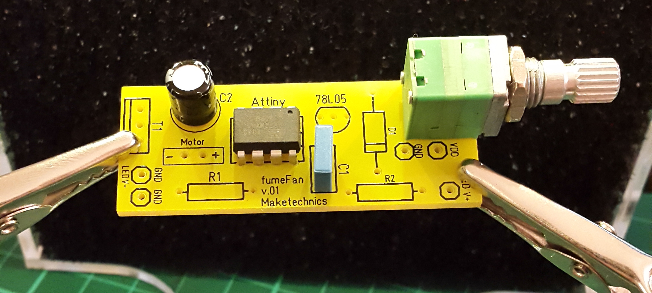
Kit Contents Overview
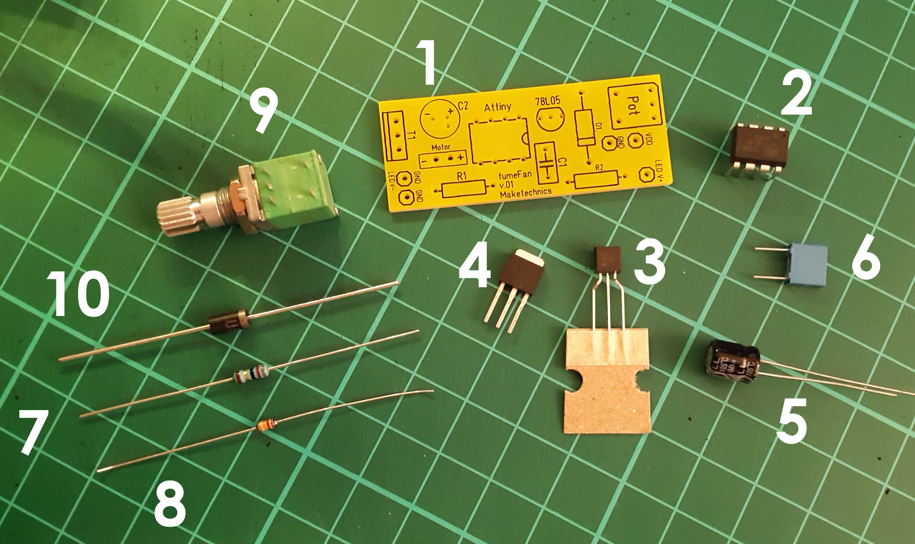
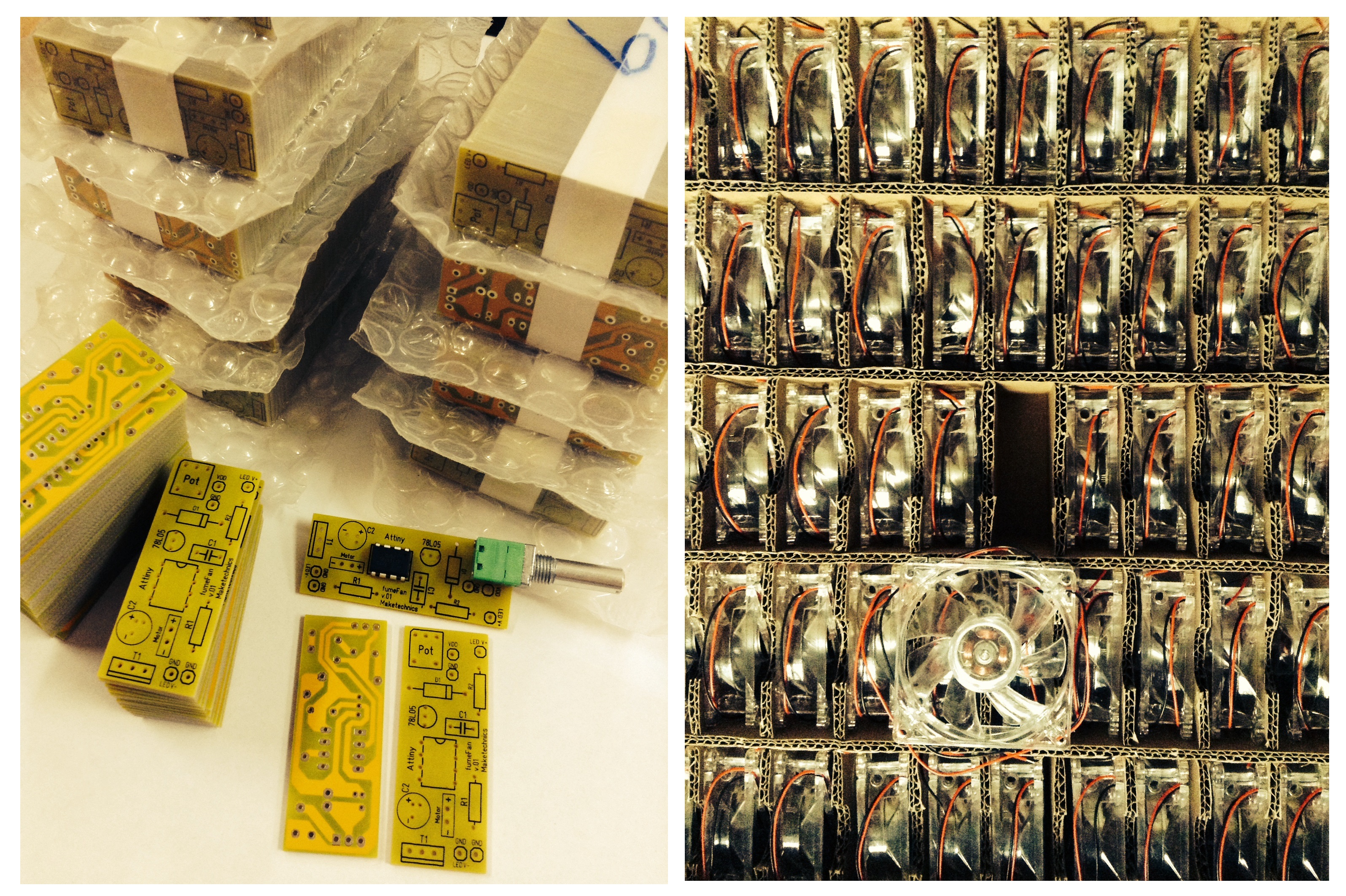
Check whether you have all the parts required to assemble the PCB:
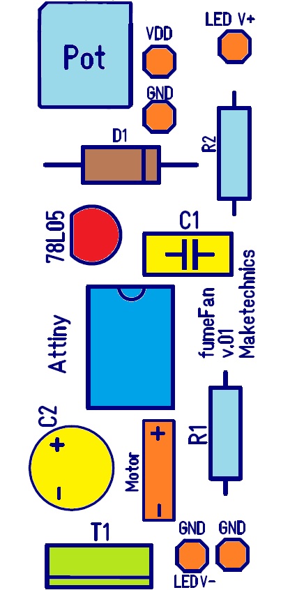
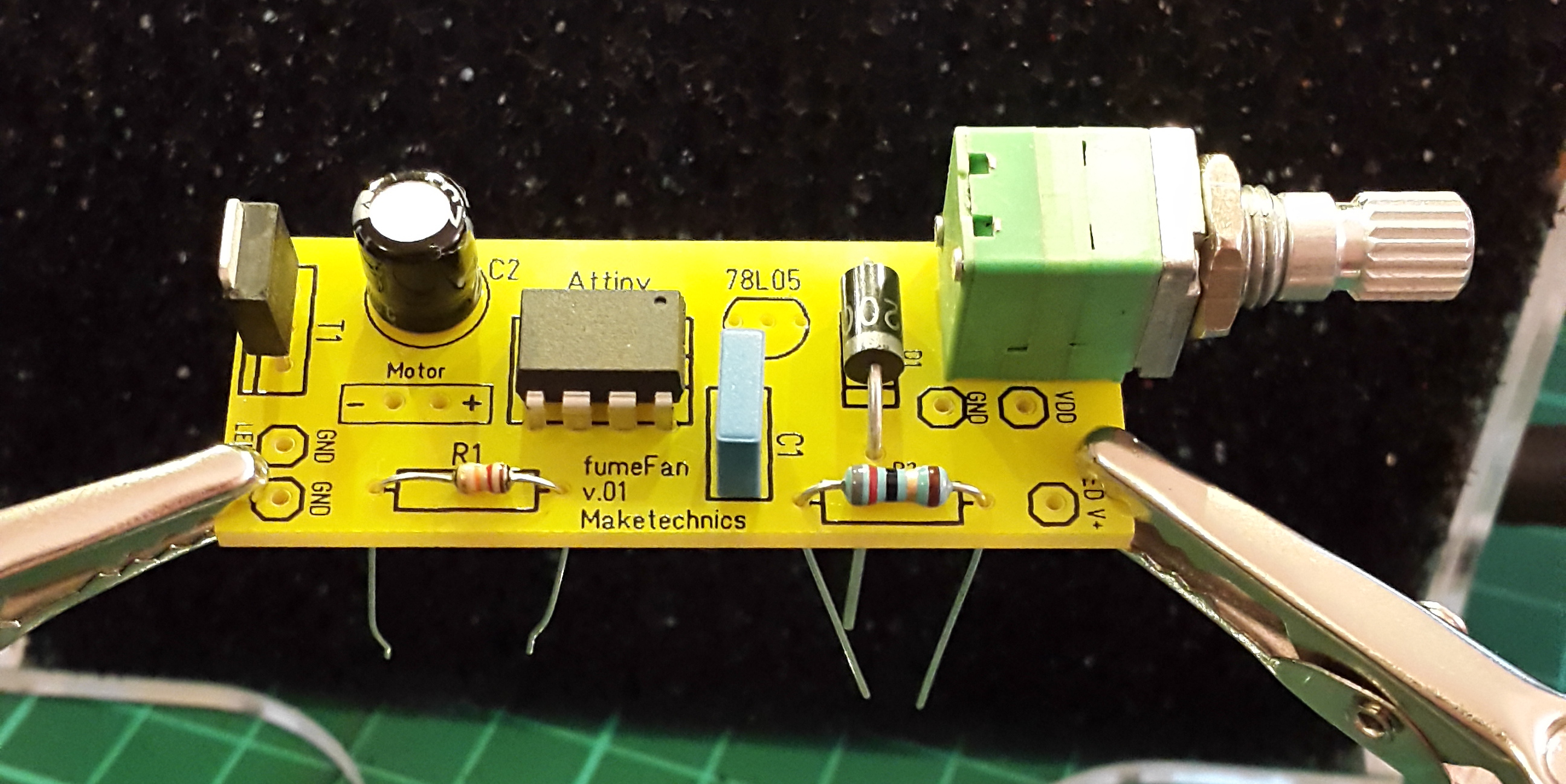
- PCB - fumeFan v.01 in our case
- Attiny 45 microcontroller
- 78L05 - 5V regulator IC
- T1 - NCH MOS transistor
- C1 - 47 uF 25V electrolytic capacitor
- C2 - 47 nF 100V film capacitor
- R1 - 12kΩ resistor
- R2 - 82Ω resistor
- Pot - 50 kΩ Single gang potentiometer with a switch
- D1 - UF2003 diode
Insert Attiny
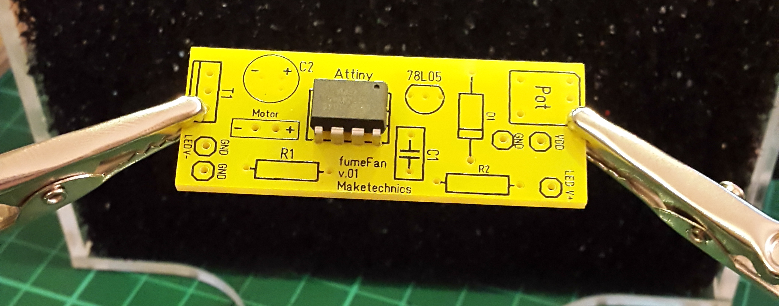
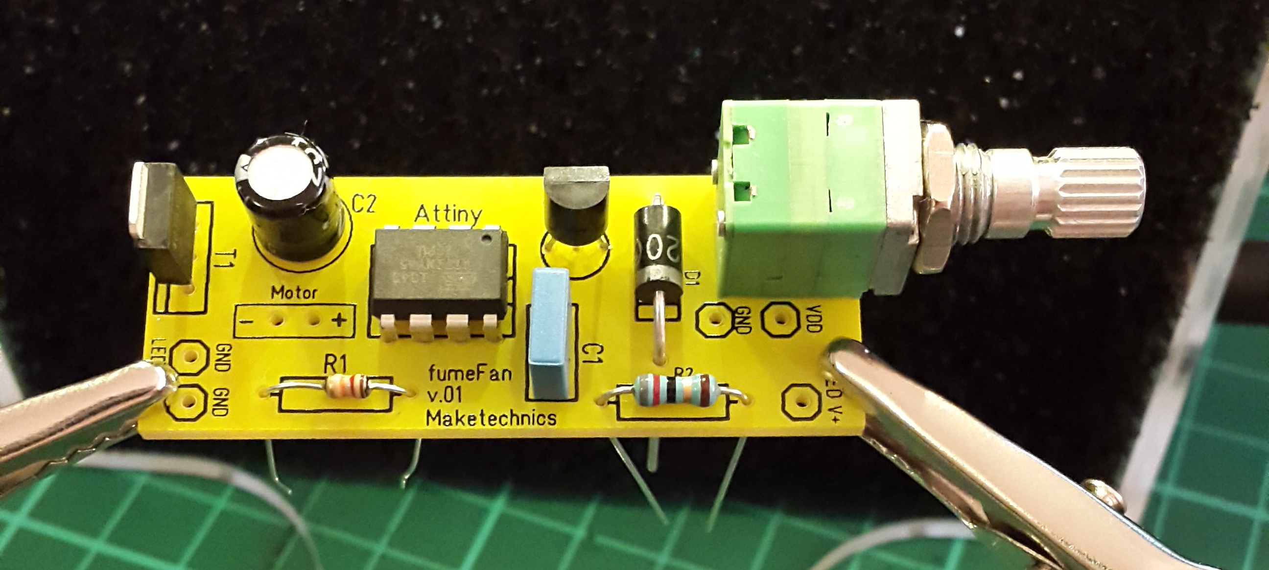
Find the dot in one of the corners of the microcontroller and align it to the drawing on the PCB. There is a small notch on the PCB that marks the chip end with the dot.
Note* You may want to solder a chip socket to the PCB in case that you want to change the microcontroller later. This is not required at this stage as the microcontroller you are provided with is already programmed and ready to use for this occasion.
Capacitor C1
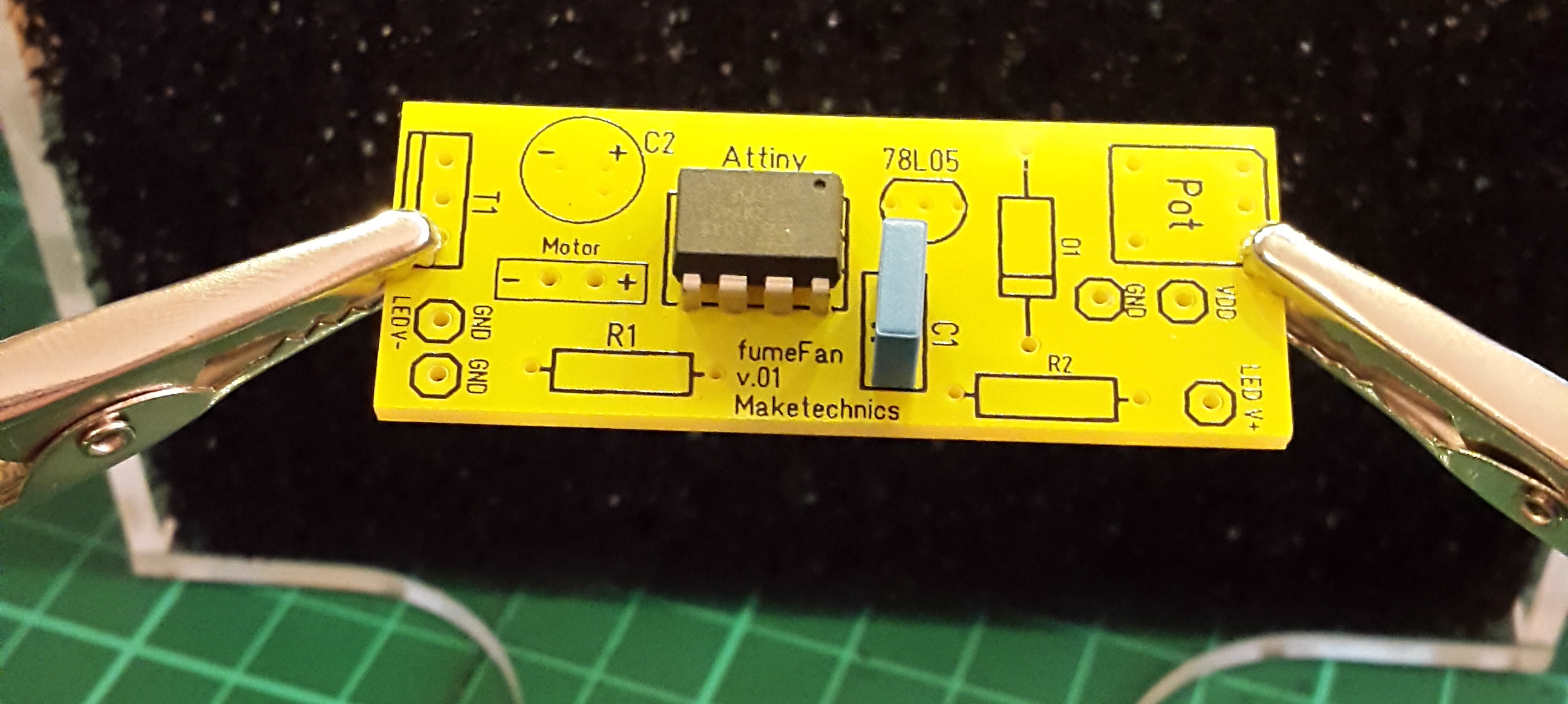
Capacitor C1 does not have explicit polarity, so just insert it.
Capacitor C2
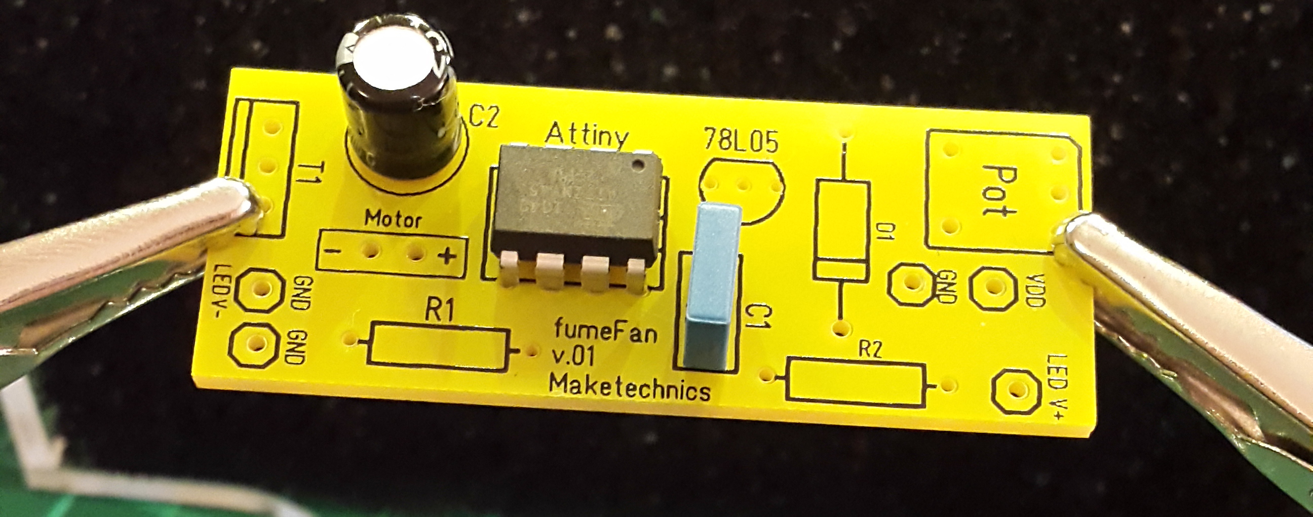
IMPORTANT: Insert the electrolytic capacitor in the way that the printed minus sign on the PCB aligns with the side of the capacitor that has a grey dash with printed minus signs.
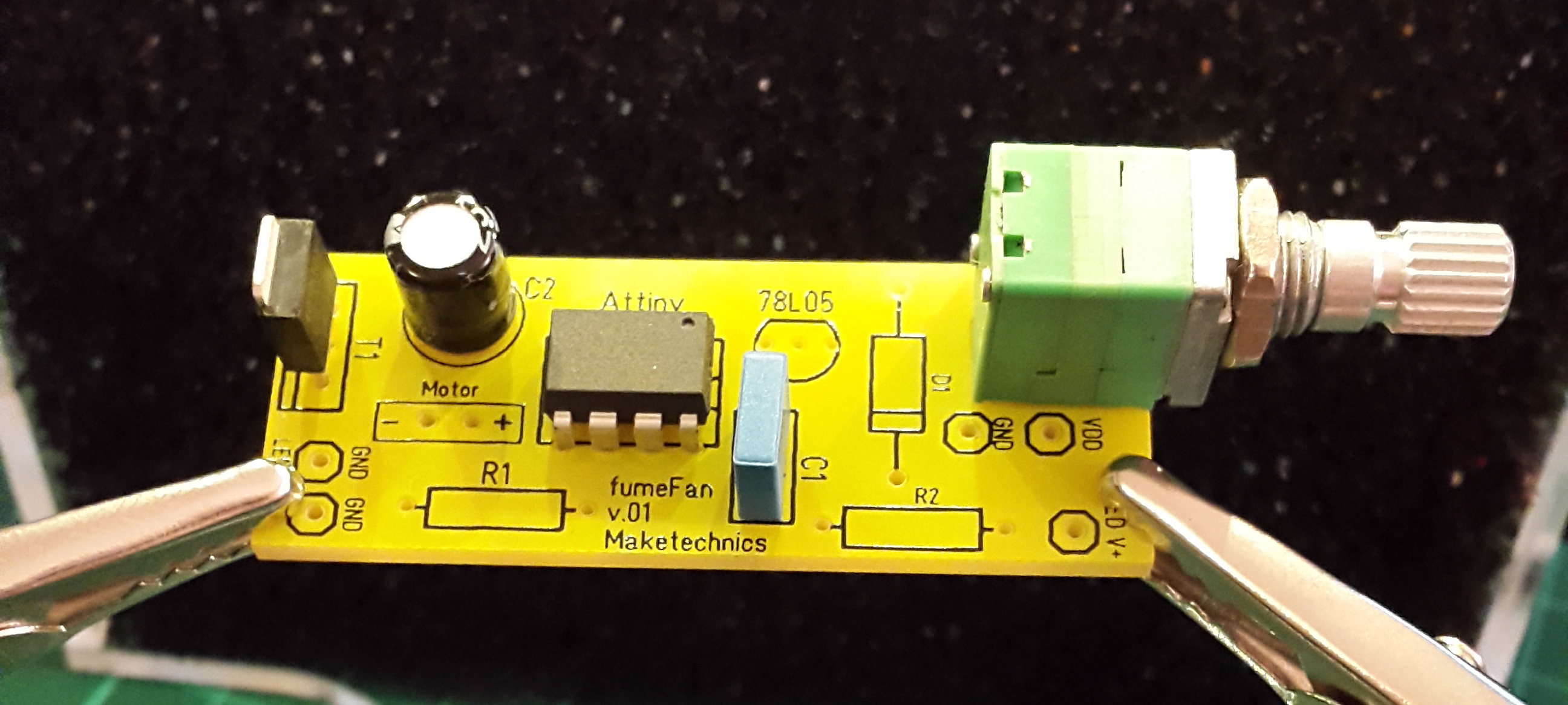
Potentiometer
Locate the "Pot" label and the five holes that the potentiometer has to go through.
Transistor T1
Align the drawing on the PCB with the transistor correctly. The thin line on the PCB drawing has to align with the metal side of the transistor as on the image.
Resistor R1
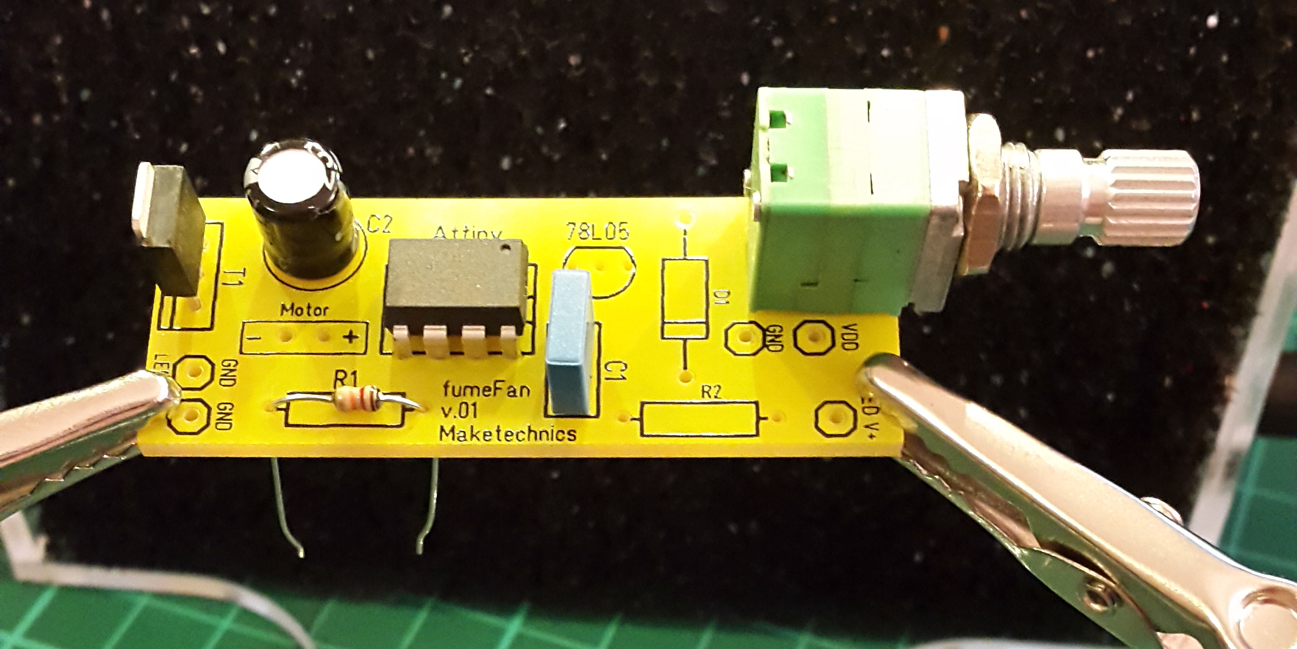
Insert the 12 kΩ resitor in the "R1" position.
Resistor stripes as follows:
- Brown
- Red
- Orange
- Gold
Resistor R2
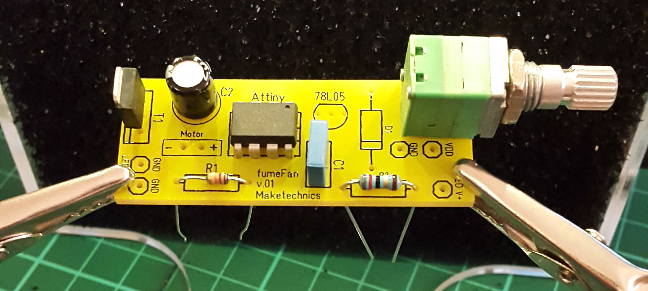
Insert the 82 Ω resitor in the "R2" position.
Resistor stripes as follows:
- Grey
- Red
- Black
- Gold
- Brown
Diode D1
Insert the diode as shown with the silver mark aligned with the drawing on the PCB.
5V Regulator IC
Insert the 5V regulator IC aligning the curve of the IC with the drawing on the PCB.
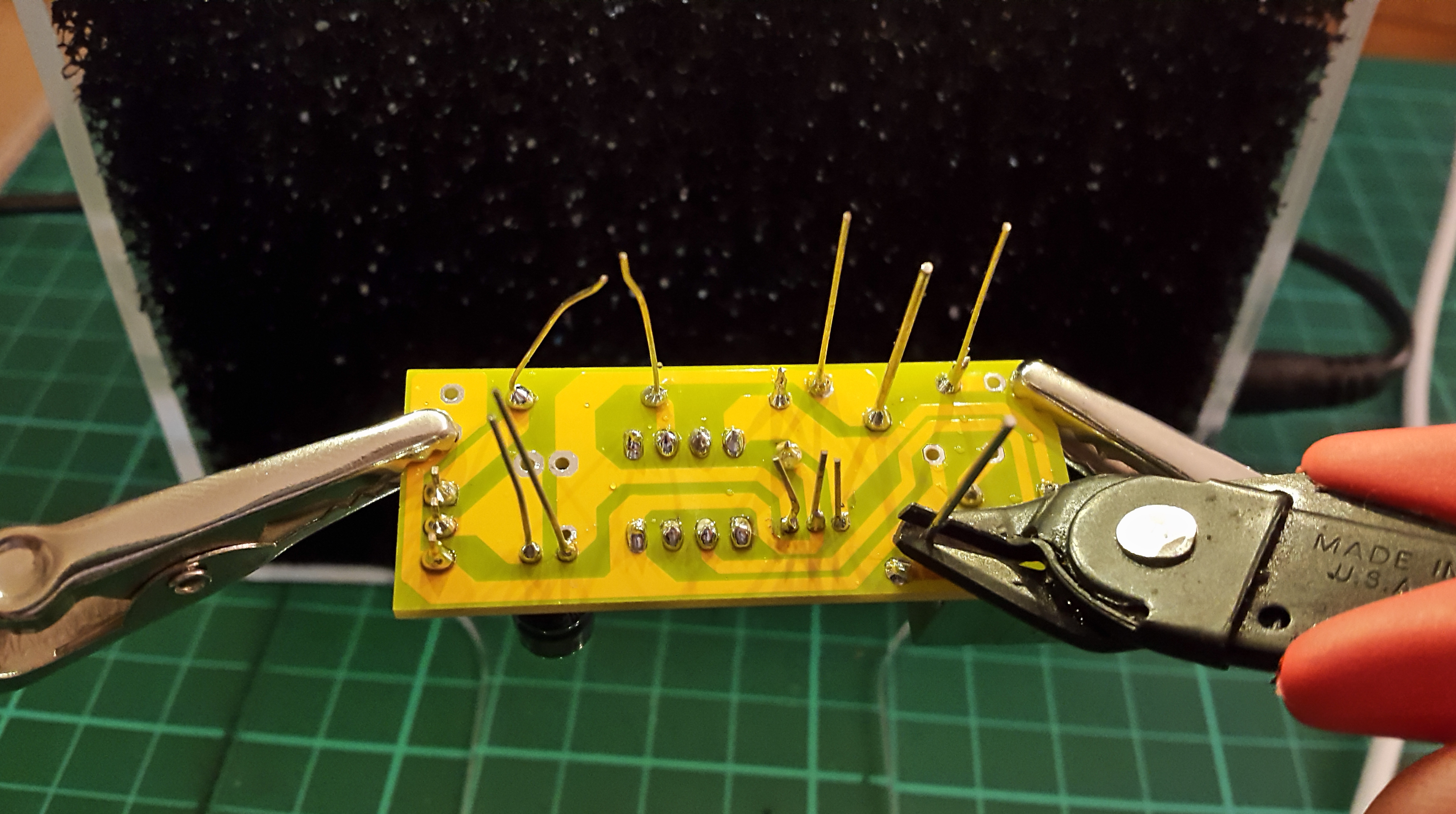
Flip the PCB
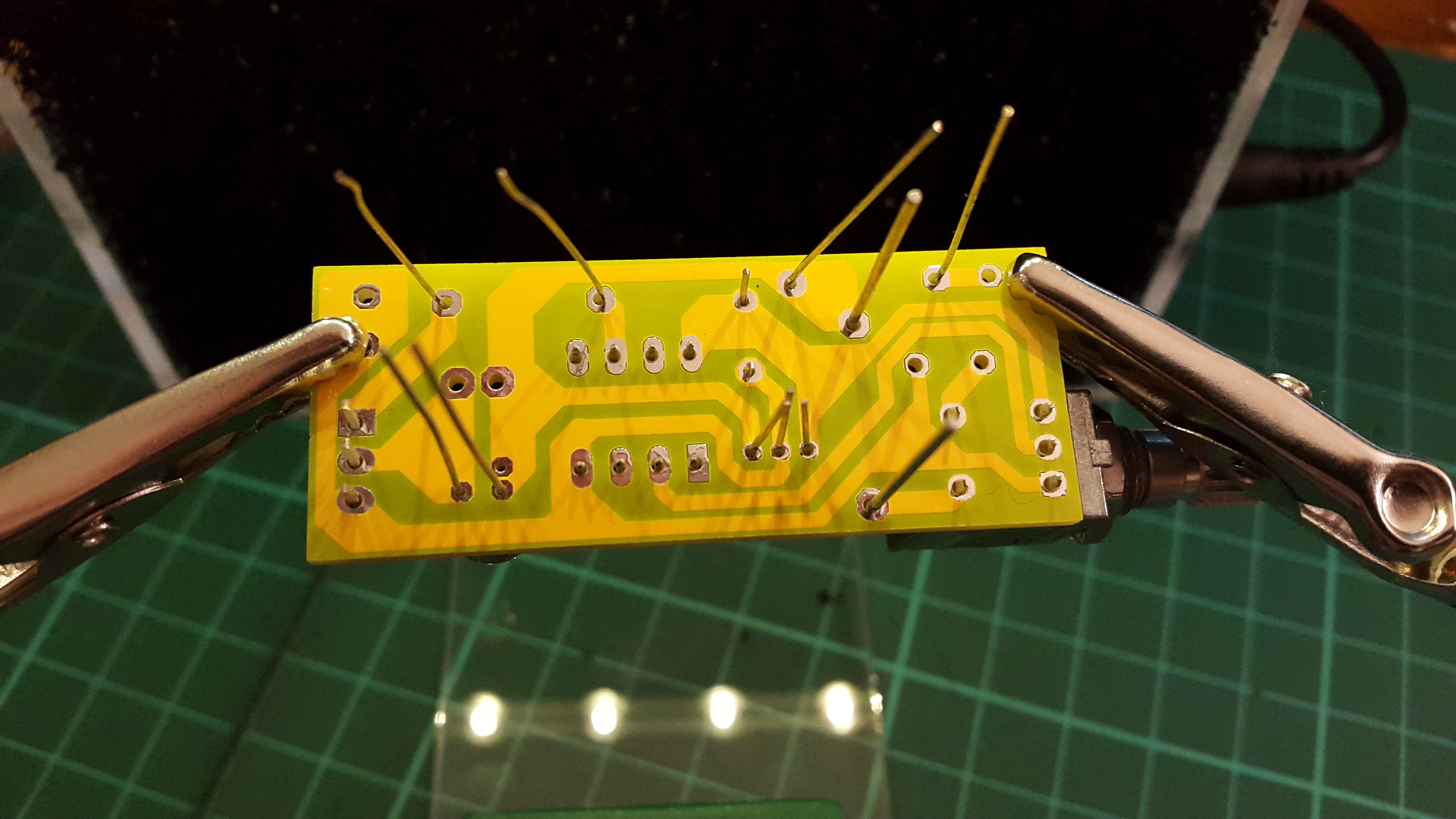
You will now be able to solder all the legs of the components onto the PCB.
Of course you can do that one by one each time you insert a component or all at once at the end.
Solder
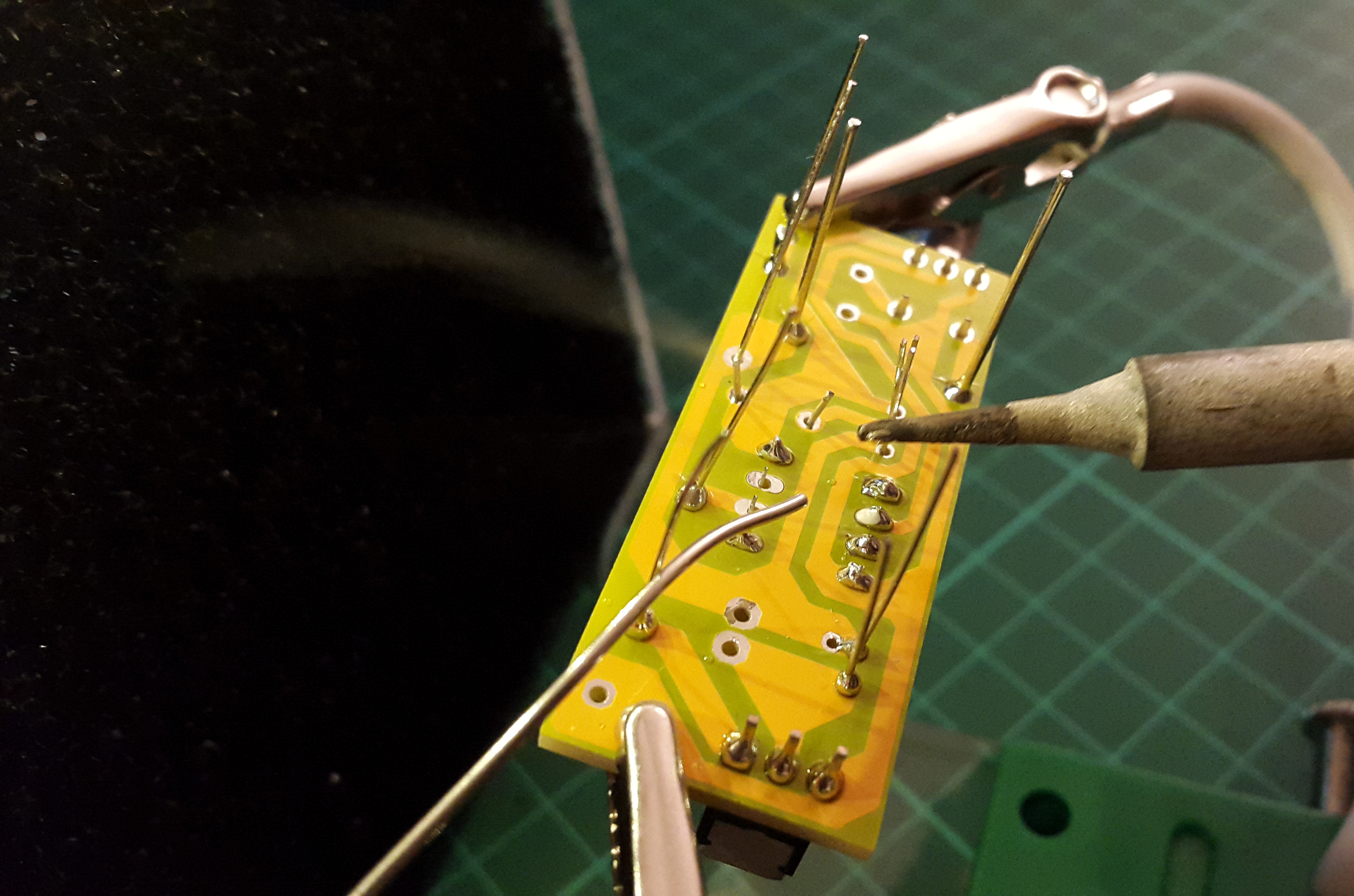
This is easy, touch the tip of the soldering iron to BOTH the leg of the component and the metal pad on the PCB. Then add some soldering wire and wait for it to leak melted.
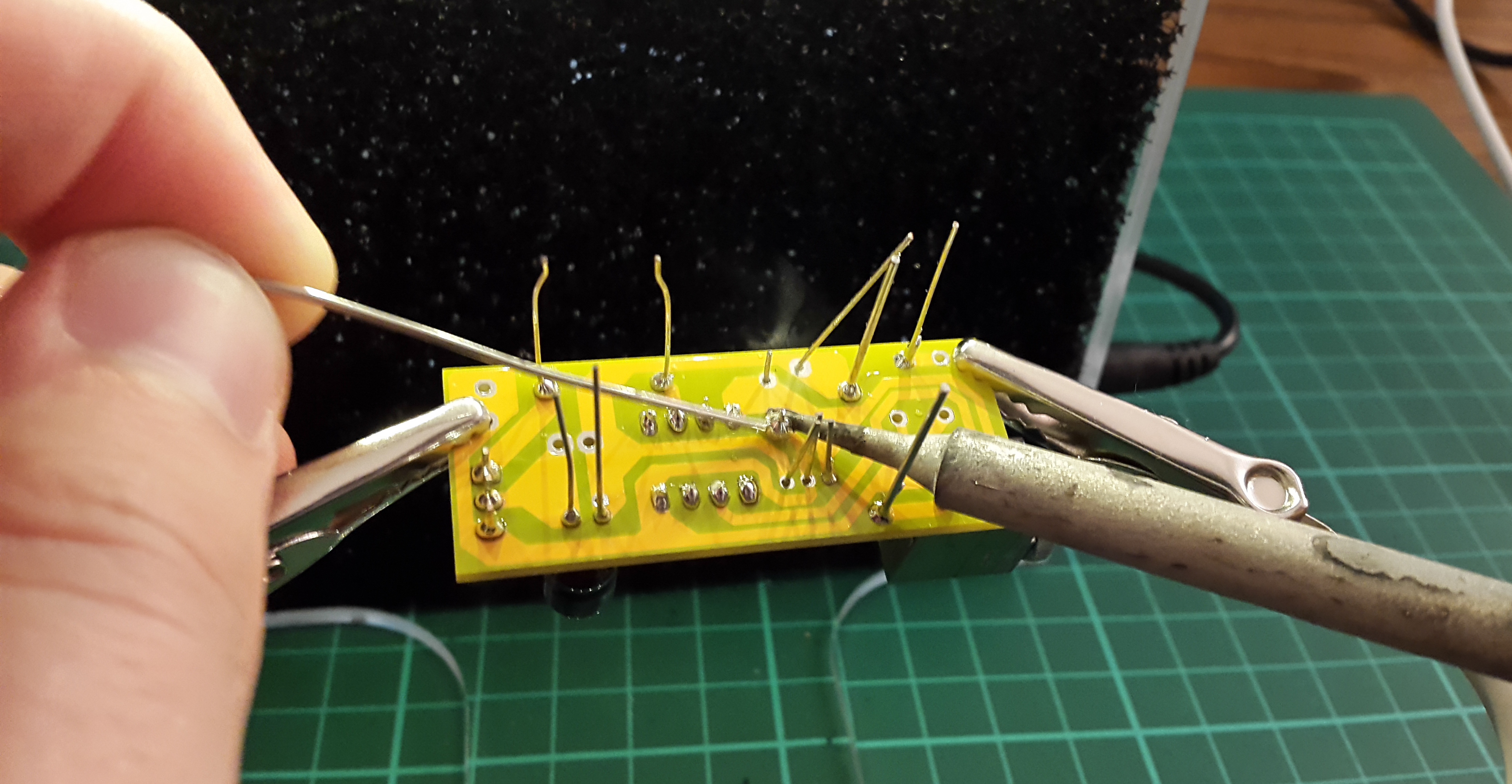
Trim
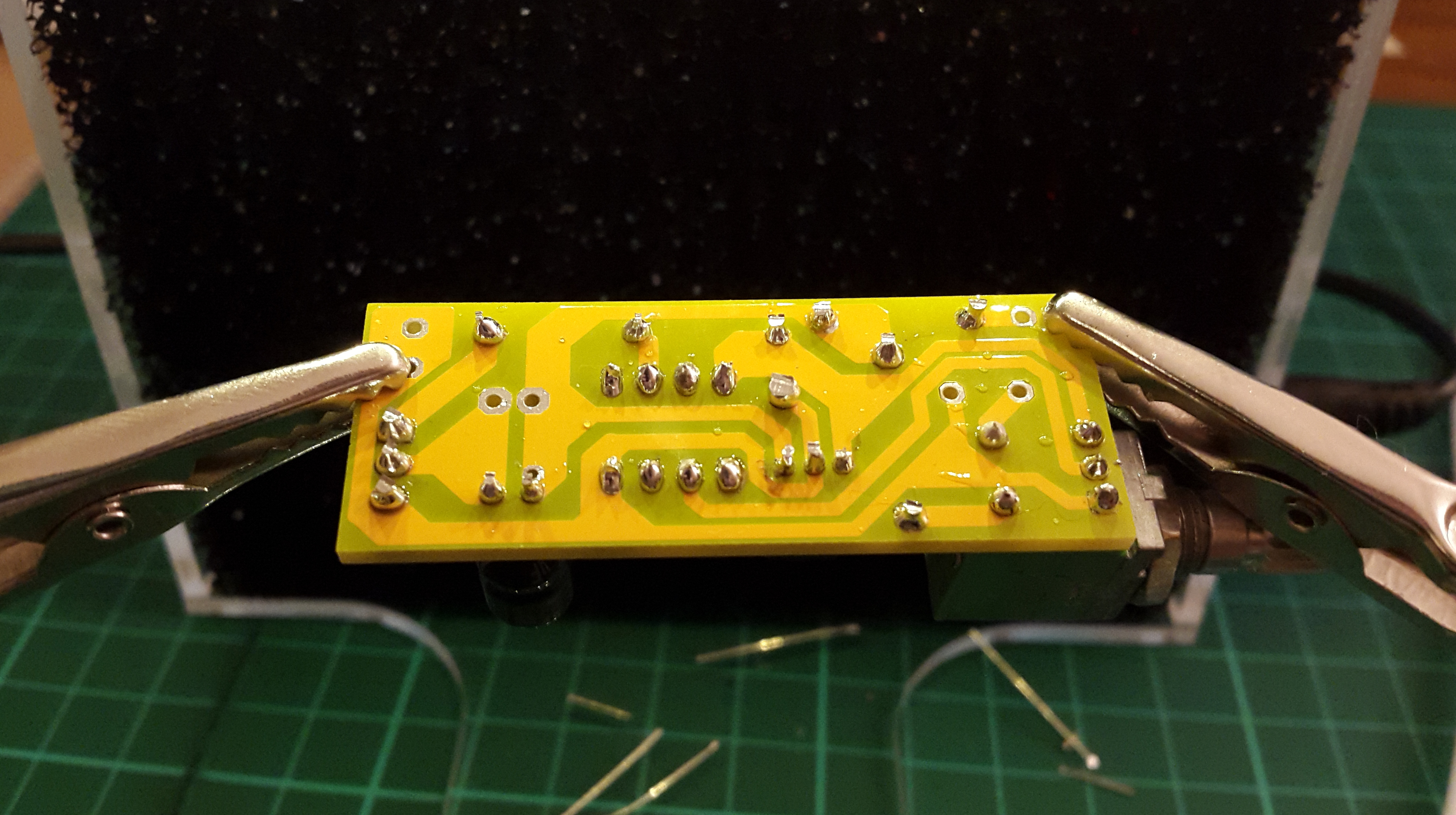
Trim the legs and you are ready!
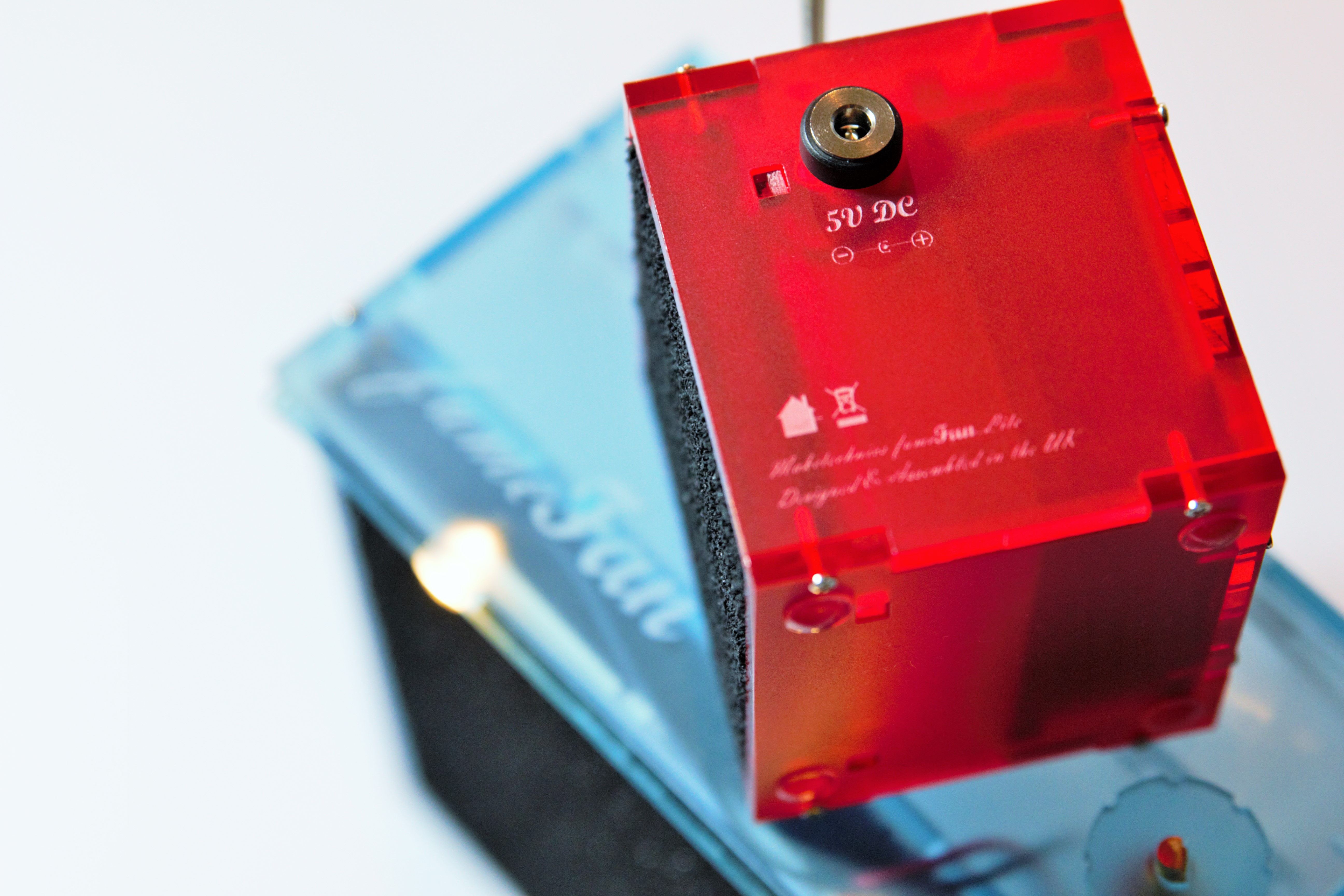
Next step is to solder the power input and output wires.