How to Reflow Solder an LED Emitter on a PCB or MCPCB
by MatthewS225 in Circuits > Electronics
6869 Views, 10 Favorites, 0 Comments
How to Reflow Solder an LED Emitter on a PCB or MCPCB

3 easy ways to refleow solder a Cree LED emitter onto an MCPCB or PCB. No reflow oven or special tools required.
This tutorial will show you in a few simple steps how to reflow solder popular LED emitters like Cree XML, Cree XM-L2, Cree XHP-50, Cree XHP-70 Cree XP-G2, Cree XP-G3, and more, so that you can do them at home.
Using only a few simple tools you can do this at home. In the video I will demonstrate three methods.
1. Using an electric skillet (with used parts 10:14 ).
2. Hand held torch or heat gun 17:00
3. A lighter. 18:30
How to test if they are working 13:51
How to clean 15:26
This could also be done using Weller soldering iron to heat the base of the MCPCB. The demonstration will also include how to use Kester no clean soldering paste and flux, or standard lead tin rosin core solder.
If you would like to buy high power Cree LEDs you can get them here. http://asflashlights.com/21-led-emitters
For the copper mcpcbs such as SinkPad order here. http://asflashlights.com/22-mcpcbs
If you enjoyed this video please click "like" and share with others.
Thank you for watching :)
Step:1 Choose Your LED and MCPCB.
.JPG)
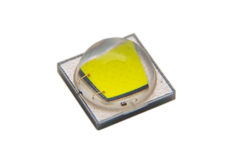
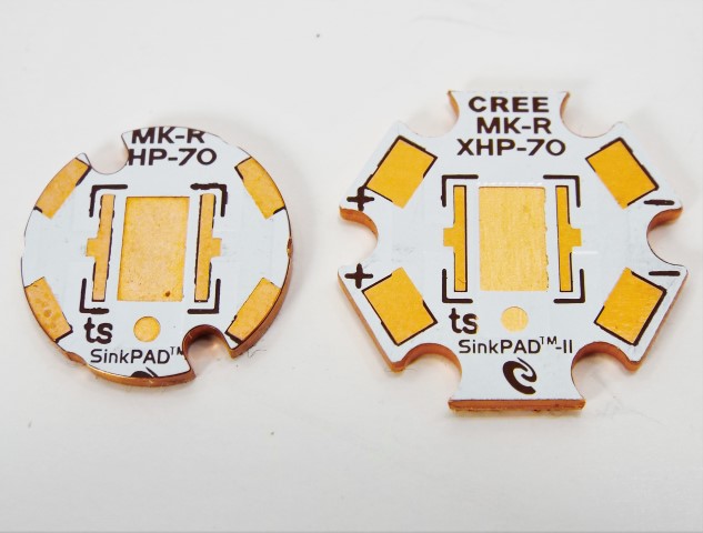
For this tutorial we are going to use Cree XHP-70s, Cree XM-L2s and copper direct thermal path MCPCB. The XHPs will go on a SinkPad, and the XML2 on a noctigon.
Step 2: Next Choose a Heat Source.
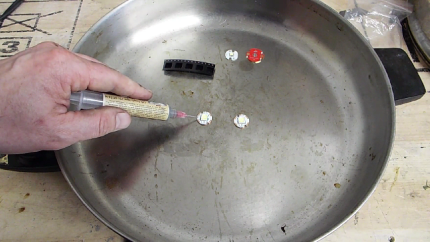

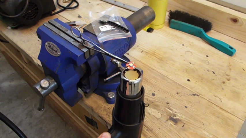

A few good options are.
1. An electric skillet ( my favorite)
2. A propane torch and a metal base
3. A heat gun
4. A lighter
Step 3: Adding the Solder
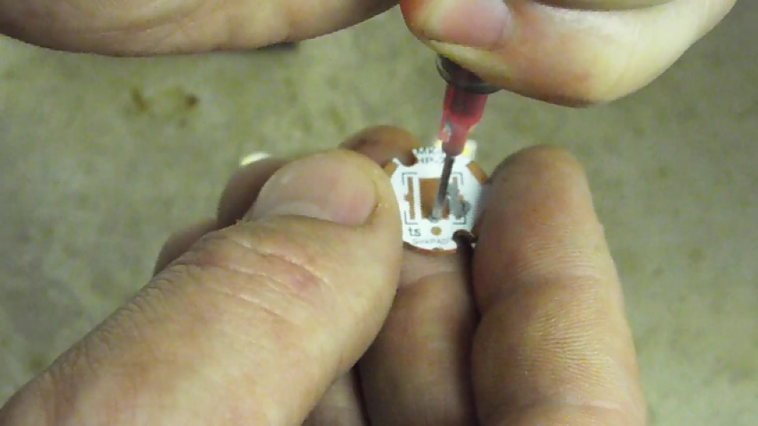
The best thing to use is solder paste. However if you don't have any you can just tin the pads of the mcpcb with lead tin solder. Some flux is recommended if you do.
Step 4: Placing the LED
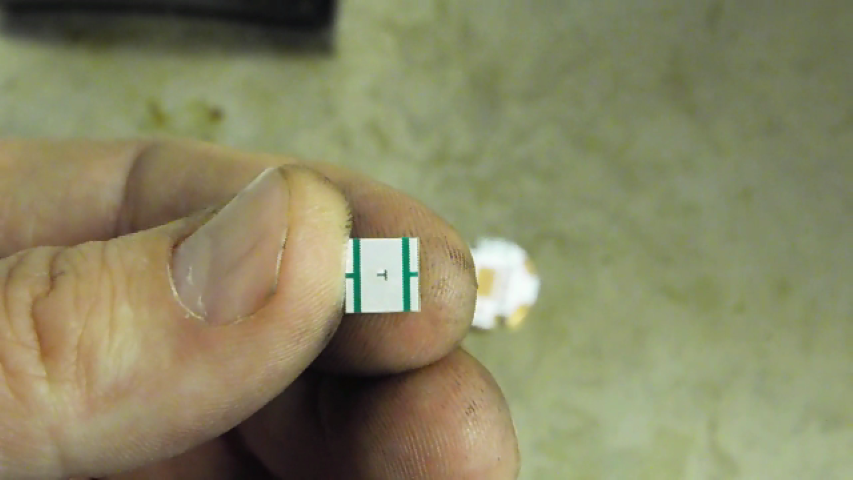
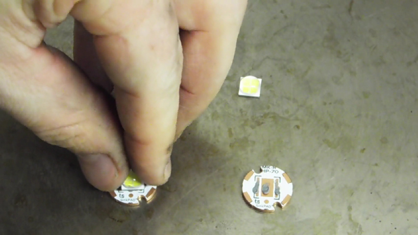
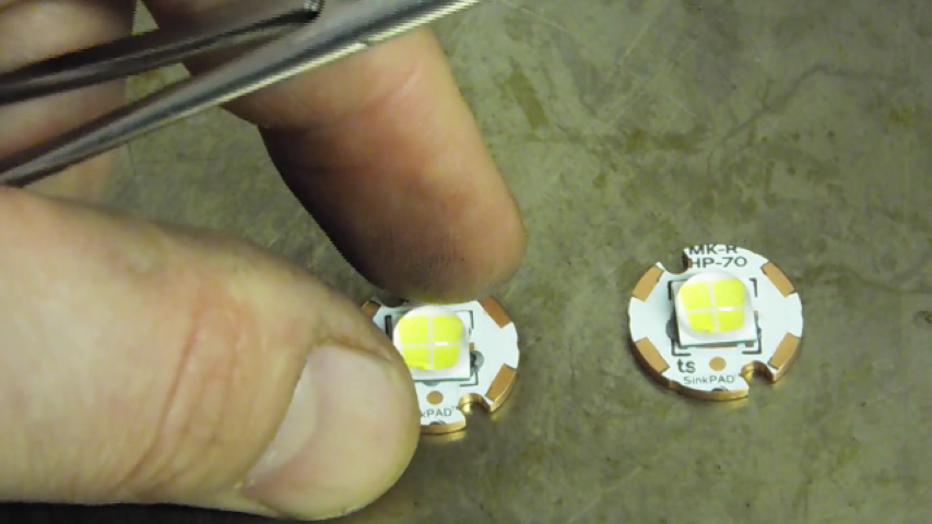
With the solder in place we need to check the direction the LEDs need to go on. Each LED will have its own indicator which can be found on its PDF data sheet on the web.
The XHP-70 has a "T" shaped arrow on the bottom that points toward the positive side of the MCPCB. The XML2 has a black dot in the top right hand corner that indicates negative.
Once that is done simply place your emitter on the board over the solder and your ready to go.
Now apply heat to the base of the LED star (mcpcb) till the solder melts. Bring the heat up gradually. Its best if the warm up takes at least 10-20 seconds from start to melt.
Step 5: Make It Even
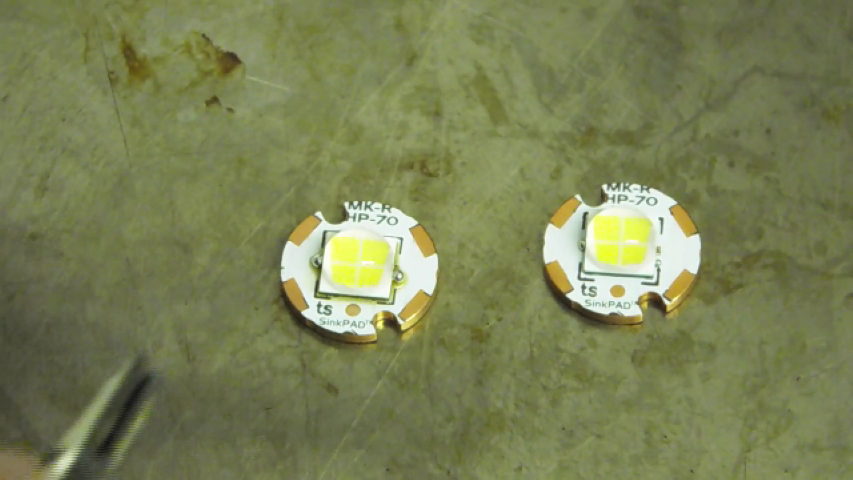
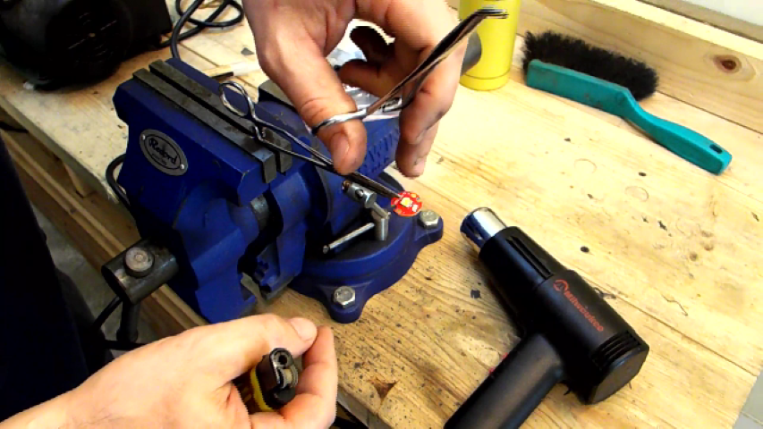
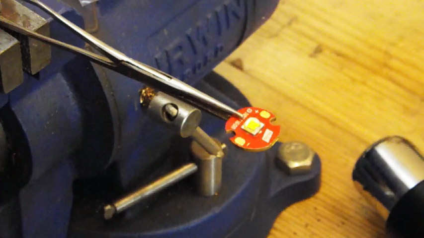
Once the solder has melted the LED will slide into place. When it does you will want to slide the emitter from side to side using a pair of hemos or pliers to make sure the solder is spread evenly between all the pads.
Step 6: Remove the Extra Solder
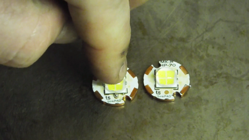
Once the solder is spread evenly you will want to "tap" on the dome of the emitter to squish out the extra solder.
Step 7: Check Your Work
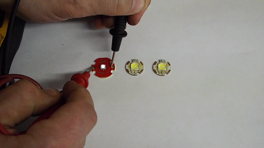
Using a DMM set to the continuity setting you can touch the leads to a 3 volt LED like XML and it will light up if you have done it correctly. 6V emitters will require a bench supply or battery pack for the test as DMM leads will not have enough voltage.
If you enjoyed this tutorial please see my other instructables and also my youtube channel. Thanks for looking :)
https://www.youtube.com/user/ForgivenMatt